
Building the XP-82 Twin Mustang in 1/32 Scale
By Ken Friend
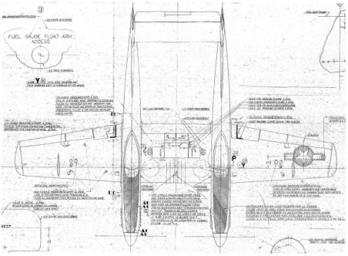
The idea for building of a 1/32 scale F-82 originated from the lack of an accurate model, in any scale, of this historic aircraft. Unfortunately, there was not a lot of technical documentation available for the XP/P/F-82 series of aircraft. Research was begun in 2008 through the Archive Staffs of United States Air Force Museum, the Smithsonian Air & Space Museum, the San Diego Air & Space Museum, the Internet and special interest aviation groups. At that time there were only two known examples, both of which resided in the Museum of the United States Air Force in Dayton, Ohio. After about a year's worth of research and the help of many modelers, there was enough dimensional information available to proceed with the project. Then, in the Spring of 2010, it was learned there are two F-82's that are being restored to flying condition. The "E" model that is being restored in Minneapolis, Minnesota was an almost complete aircraft when the restoration was begun. However, the original XP-82 prototype being restored in Douglas, Georgia had been involved in an accident and had to be "reverse engineered" to get many of the parts. Fortunately, Douglas was only 100 miles down the road from home, and several trips have yielded tons of first-hand detail information and documentation from the restoration. Accuracy was no longer an issue.
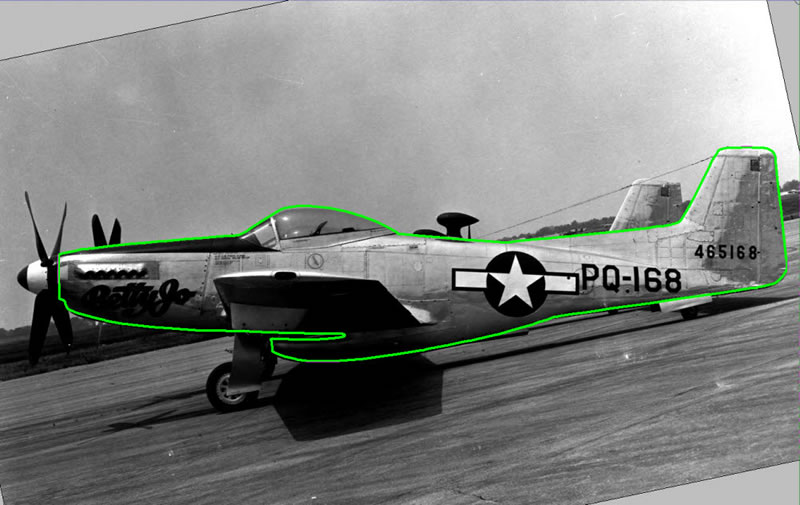
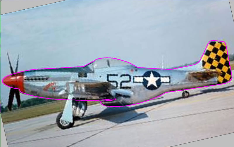
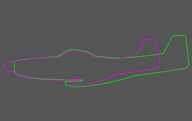
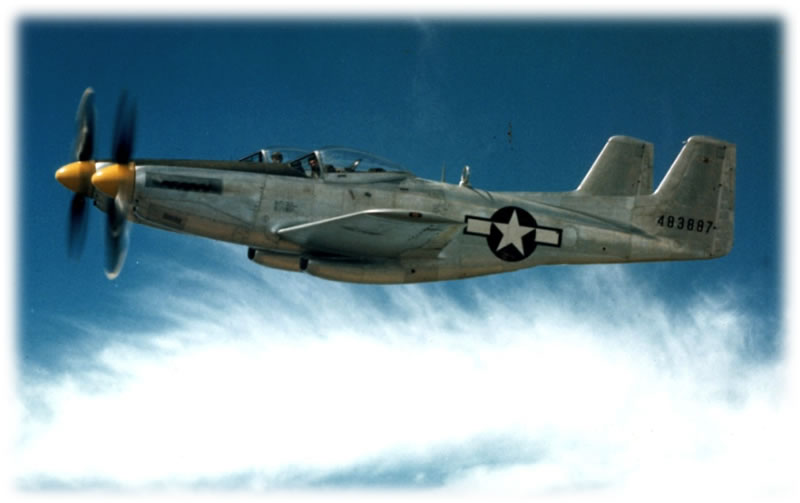
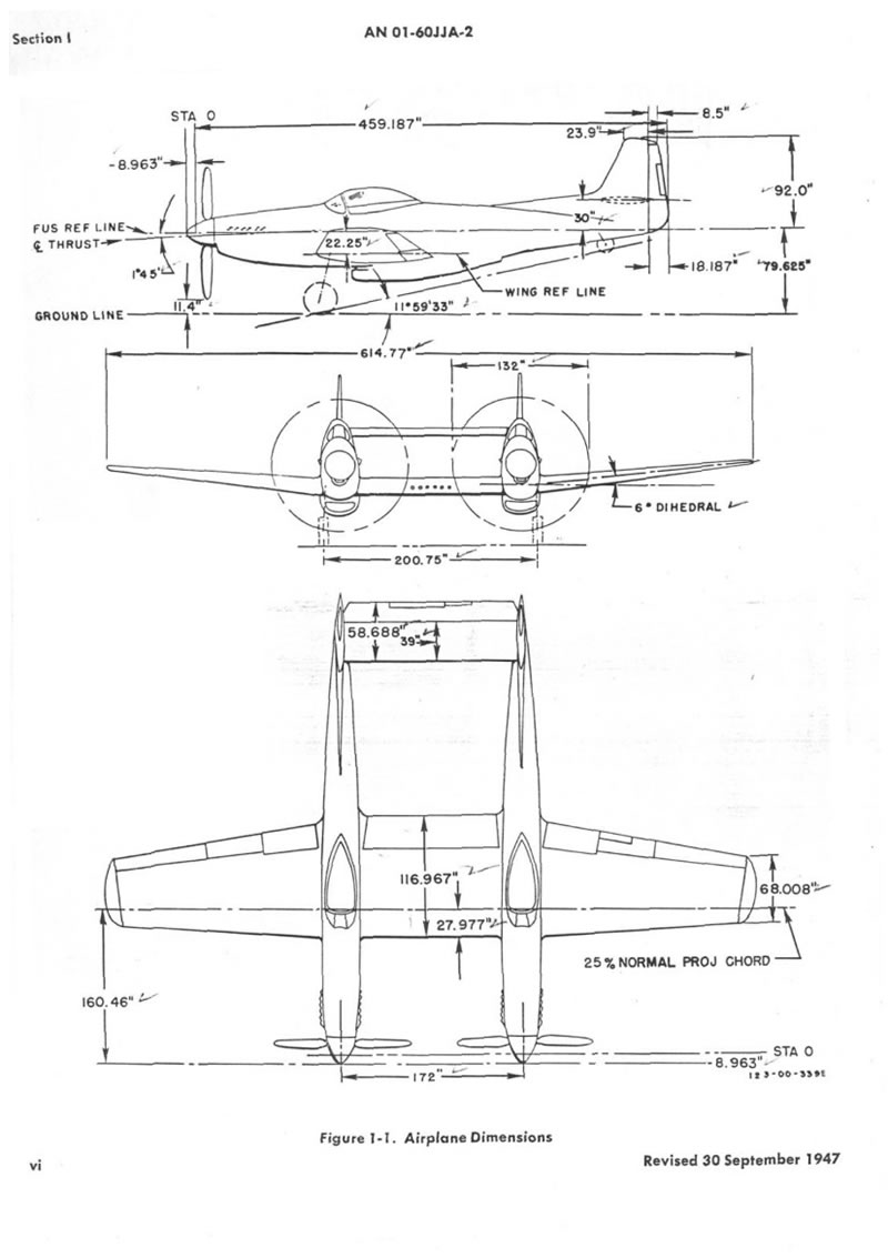
To create a non-existent model in this scale would typically require a complete "scratch" build. Detail parts would take endless time to create. However, there are 1/32 scale models of the P-51, which was the foundation for the F-82 design concept. At the time it was thought that the F-82 was about 25% P-51, so it was thought that it might be possible to utilize some P-51 kit parts to minimize new part design and development. The first step was to create 3D CAD models of the P-51 and the F-82. The CAD models were developed from original North America Aviation drawings and scaled profile pictures of both the F-82B and the P-51D. The nose contours between the two were virtually identical, but the wings were positioned further aft on the F-82. That turned out to be the extent of what could be used from the P-51 kits. The rest would have to be scratch built...
Fortunately, there were some cross-sections of both the F-82 and the P-51 available. Combining the sections with the profiles provided enough geometry to get preliminary 3D CAD models.
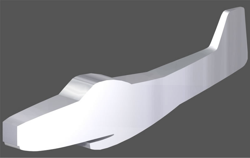
The Rough F-82 CAD Model
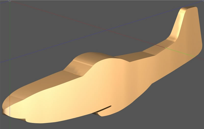
The Rough P-51 CAD Model
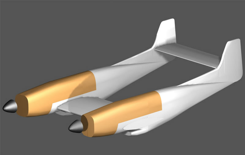
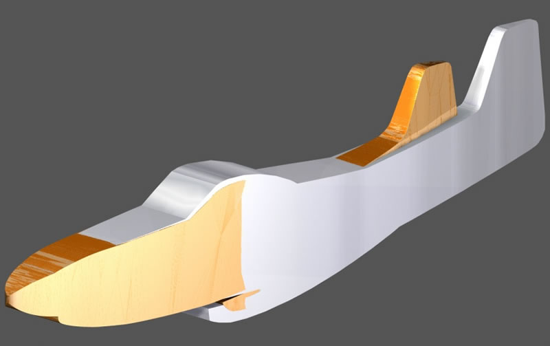
CAD allowed the models to be merged for comparison. The merged models demonstrated that the nose sections from 1/32 scale P-51D kits could be used. This would also provide many of the detail parts such as landing gear, cockpit basics, armament, etc. These parts would also allow for the fitting of engines.
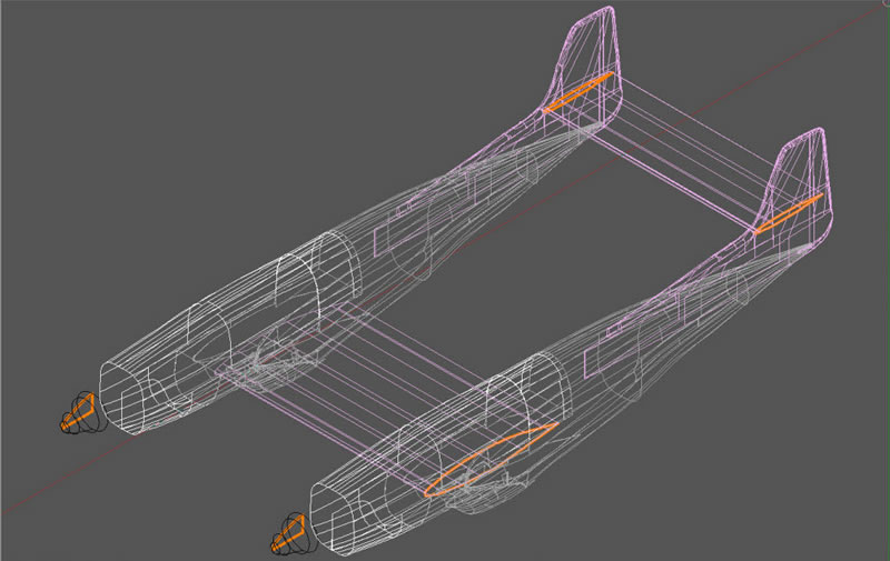
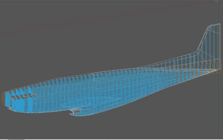
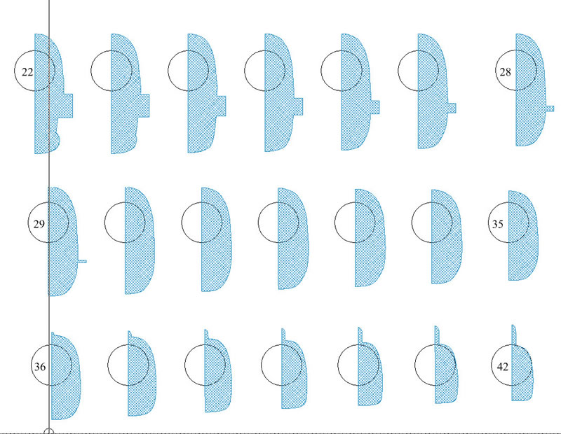
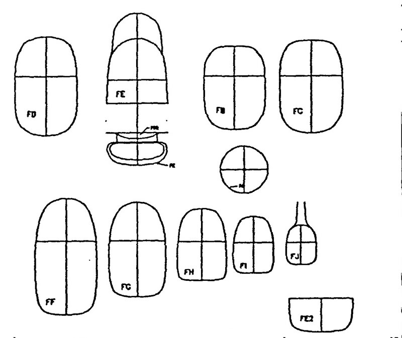
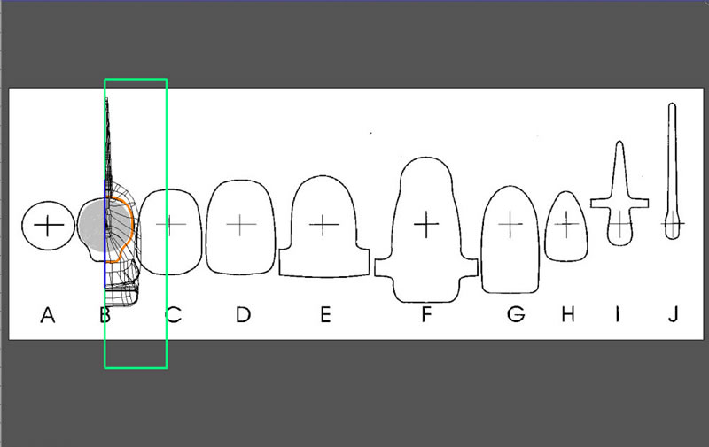
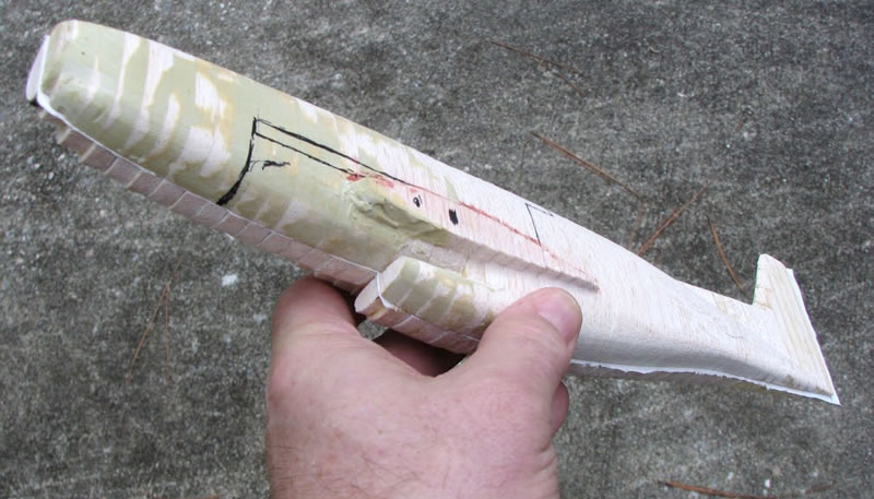
After merging the useable sections from both planes, the 3D model was completed and sections generated for the fuselages.
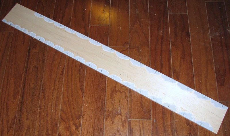
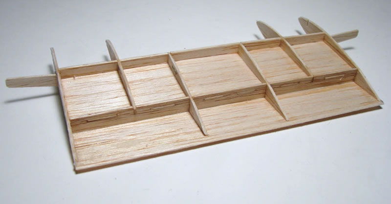
The sections were glued to 1/4" balsa, cut out, and placed on the full-sized profile printout.
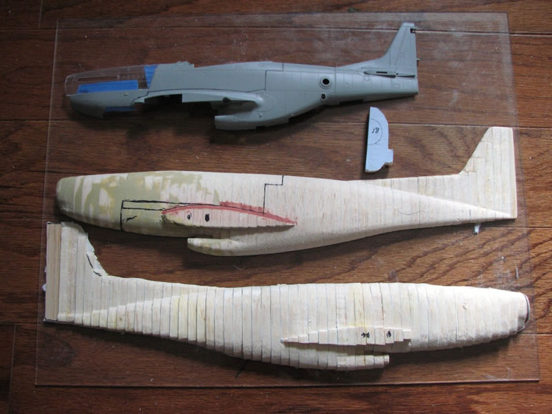
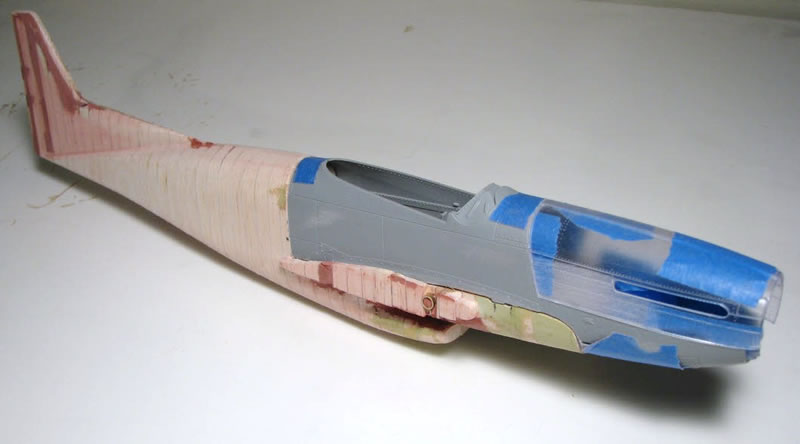
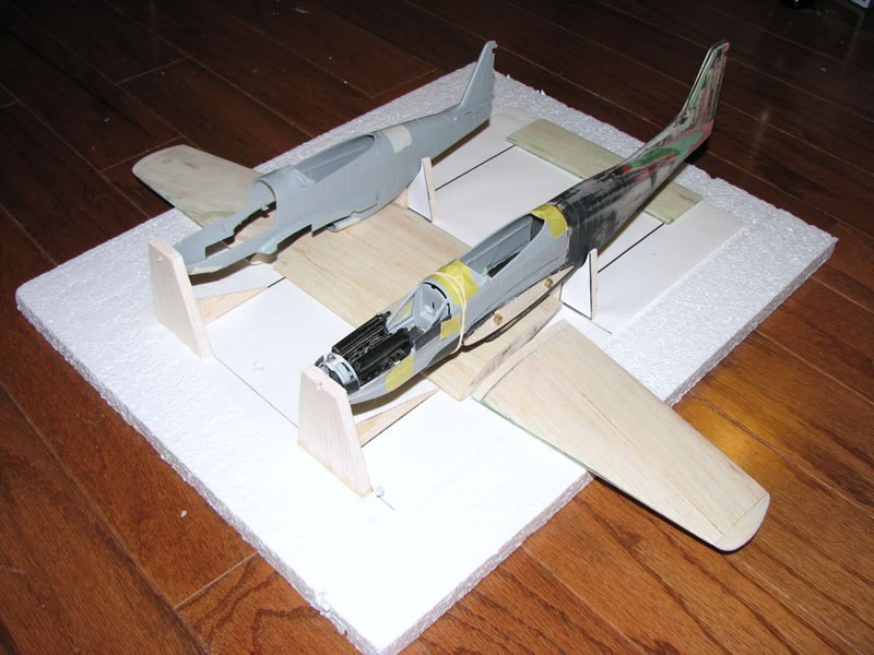
The nose section of the fuselage master was cut to accept the nose section of the P-51 kit.
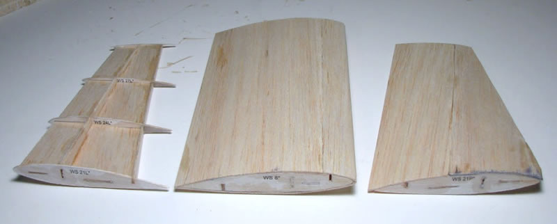
The wing sections were formed with balsa from a re-scaled 1/33 scale Modelik paper F-82 model.
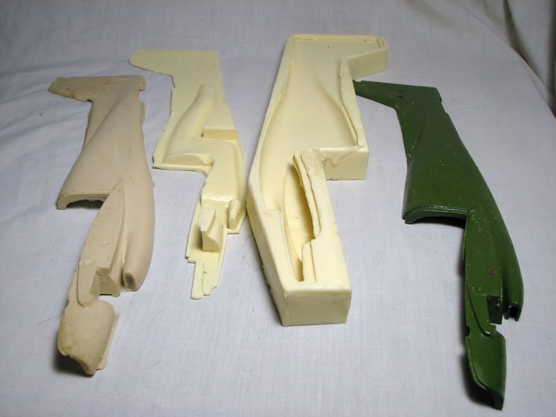
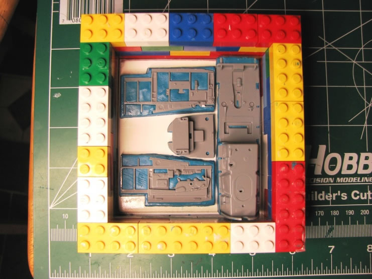
Fixtures and jigs were created to assure the alignment of all components. Silicon molds were created for the major components, and resin copies generated.
It was about this time in the project that the two F-82 restorations came to light. Other modelers started to ask for F-82 parts, and there was a request for a built-up model from one of the Investors in the XP restoration. The idea of adding the nose section from P-51 kits would be too costly to meet these new needs, so was abandoned. New masters were created that had the P-51 nose sections included. Work continues on the original build with engines, but the focus of the project shifted to the new version.
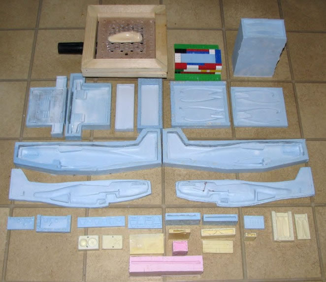
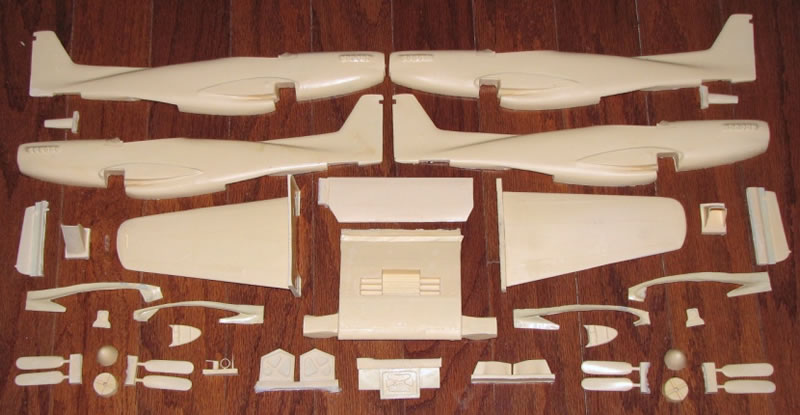
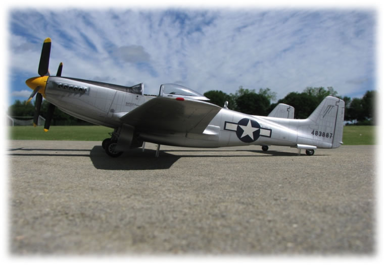
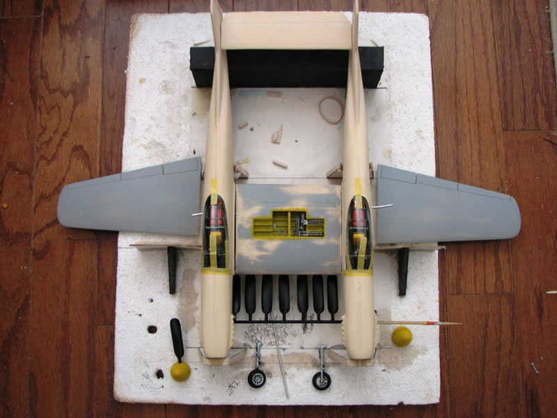
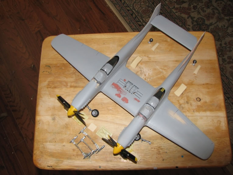
New molds were created from the modified masters, and resin copies created. A new build was started for a replica of the XP-82 prototype being restored in Douglas, Georgia.
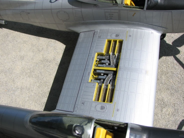
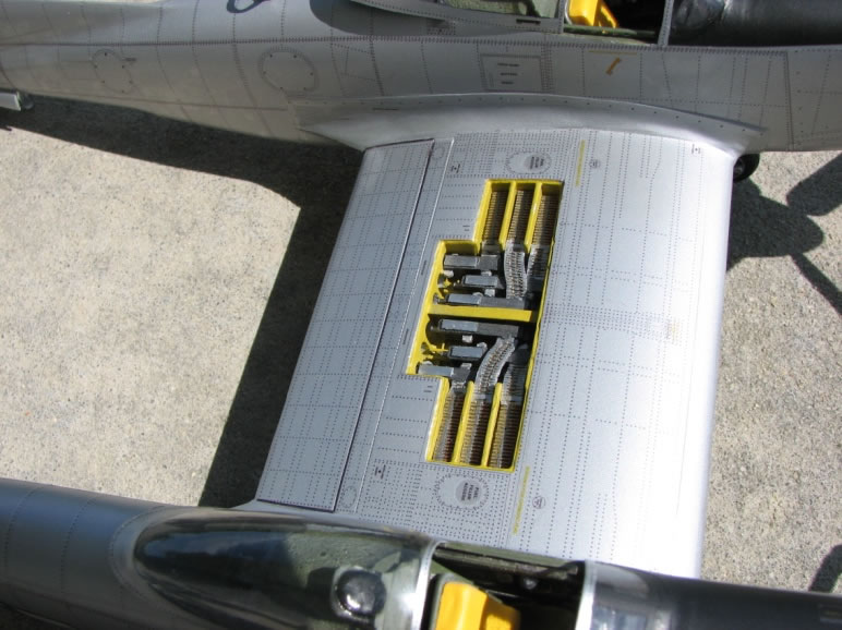
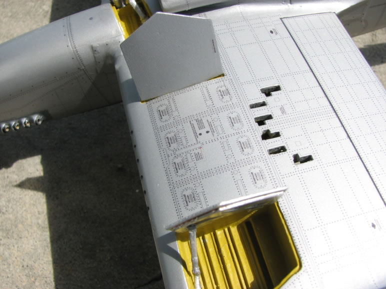
Since this model would have the cockpit, landing gear, and gun bay detail, those parts were made first. Molds of non-existing parts were made from 1/32 scale P-51D kits, and modified to replicate the XP/P/F-82 components.
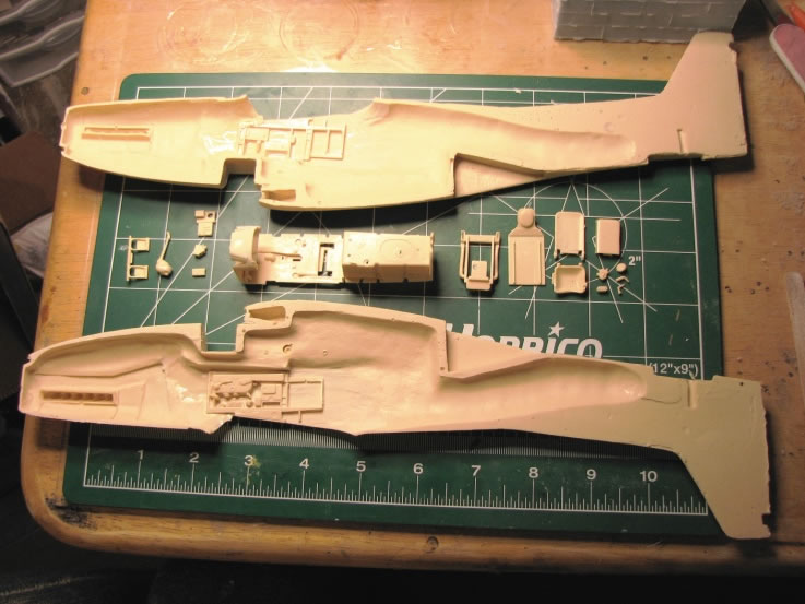
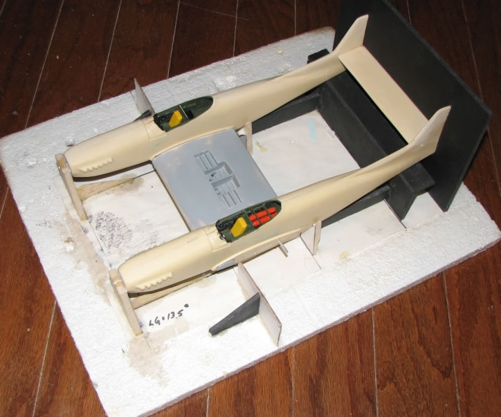
The fixtures that were developed for the original model were still useable for the new parts and configuration.
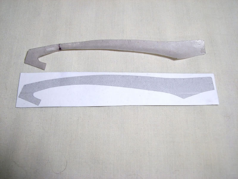
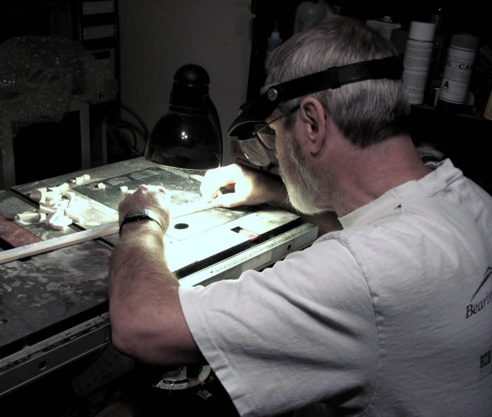
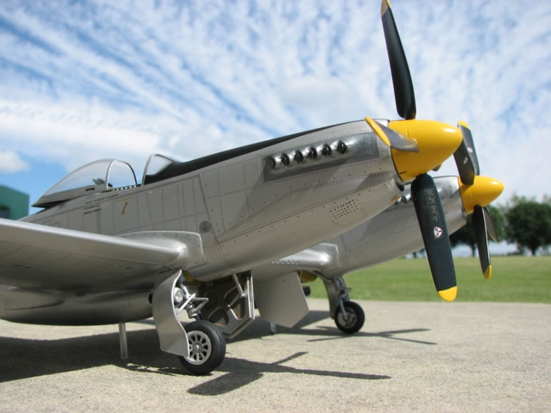
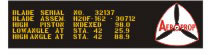
One of the more difficult pieces to create was the wing root fairing(s) due to each one being unique and irregularly shaped. The master for each one was created with card stock then hardened with thin CA (Super Glue). A mold was made and replicas created in resin. The propellers were built up and detail trimming and finishing completed.
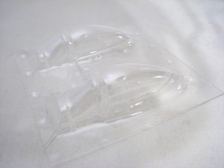
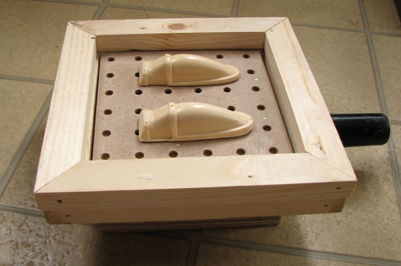
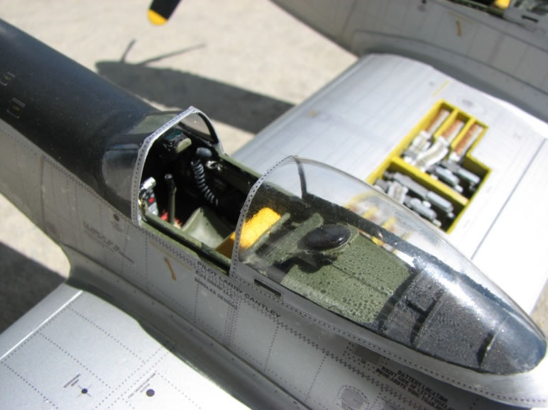
Duplicating the clear canopies also created difficulties. Two resin forms were created using a mold from an existing 1/32 scale P-51 canopy. A simple, home-built, vacuum forming box was attached to a Shop-Vac. The sheet stock was placed in the kitchen oven at 300° for 2 minutes and placed over the forms with the Shop-Vac running.
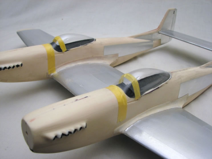
The formation lights were added by inverting costume jewelry gems and painting the underside with the appropriate colors.
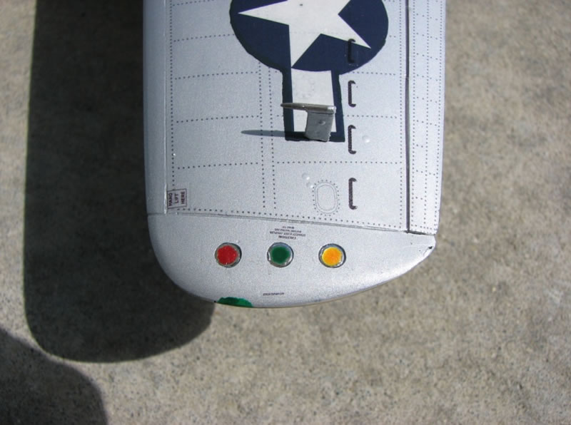
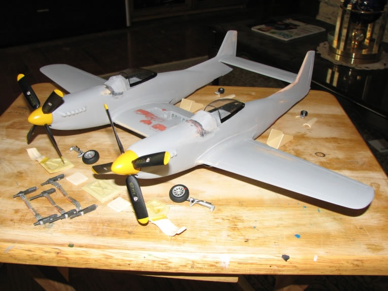
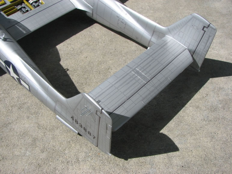
Once the parts were all assembled the model was sanded smooth, primed, and sprayed with Tamiya Natural Metal Finish silver.
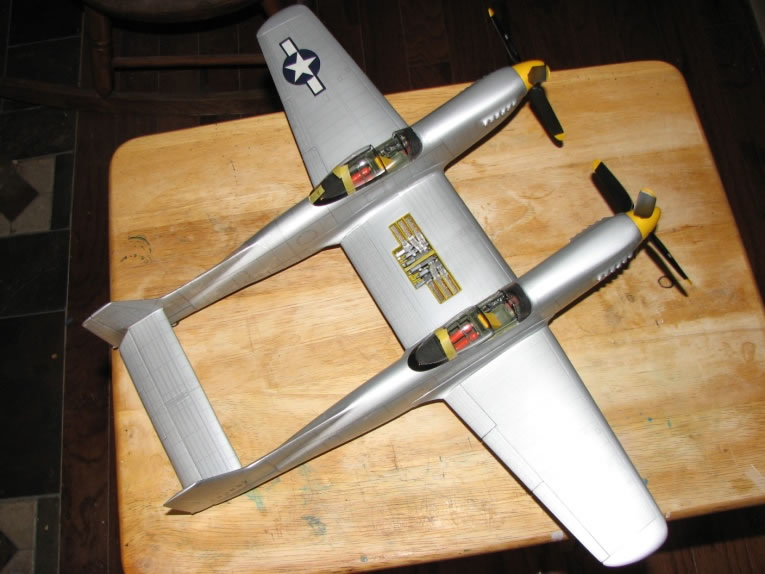
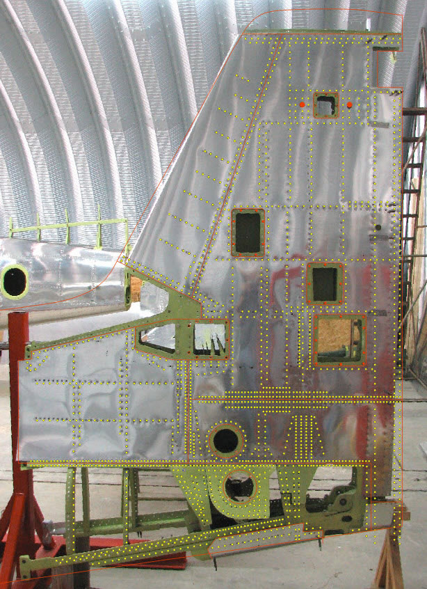
To add detail to the exterior surfaces, rivet patterns and panel lines were added by overlaying decals on the painted surfaces. The rivet patterns were developed from actual photographs of the XP-82 restoration. The photographs were brought into CorelDraw, re-scaled, then overlaid with 48,650 0.009" diameter circles. Panel lines were drawn where there were seams between panels on the real aircraft. To assure the proper fit and alignment, the patterns were first printed on clear overhead projector film. The patterns were cut out, placed on the model, and adjusted if necessary. The final printing was done on clear decal film and over sprayed with Krylon Crystal Clear satin acrylic.
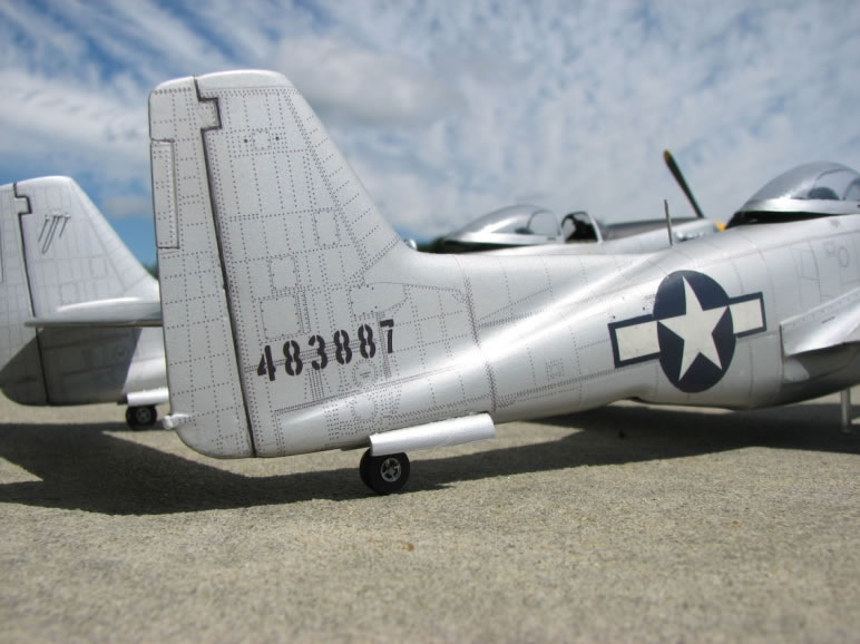
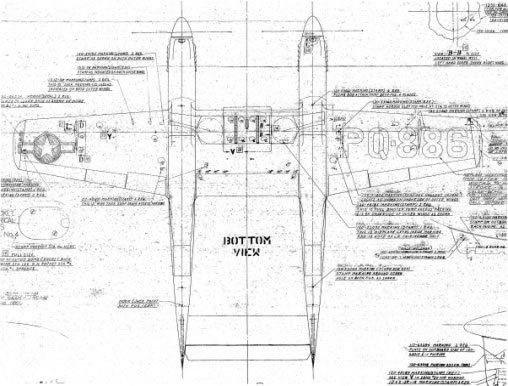
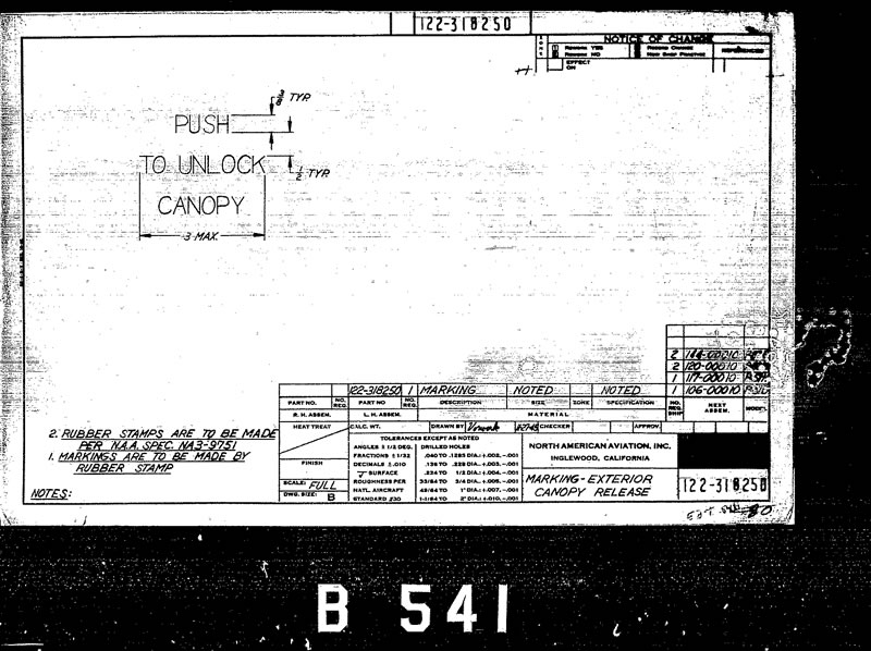
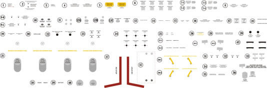
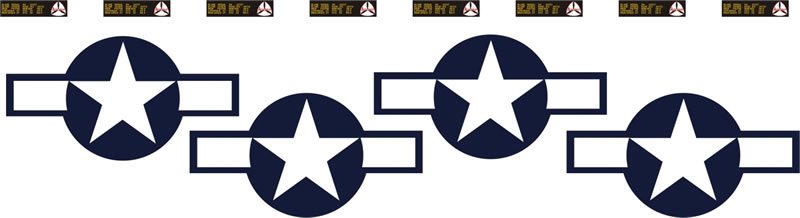
Decals had to be made for the service markings and insignia. Fortunately, the NAA drawings were available for each one, as well as the locations.
Each service marking had a supporting drawing that indicated the verbiage and font. Each marking and insignia was faithfully replicated in 1/32 scale, requiring that some letters be only 0.010" tall.
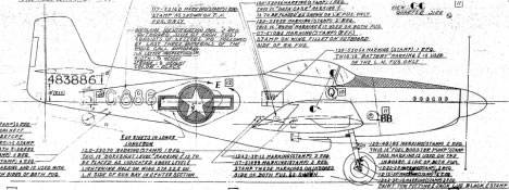
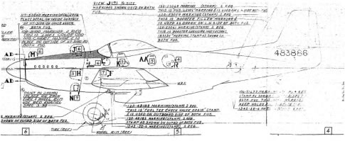
Decal sheets were then created in CorelDraw and printed on either clear or white decal film.
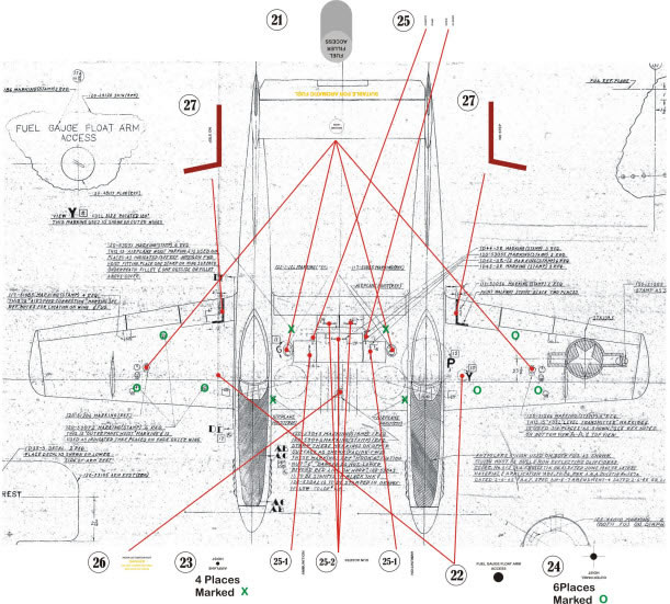
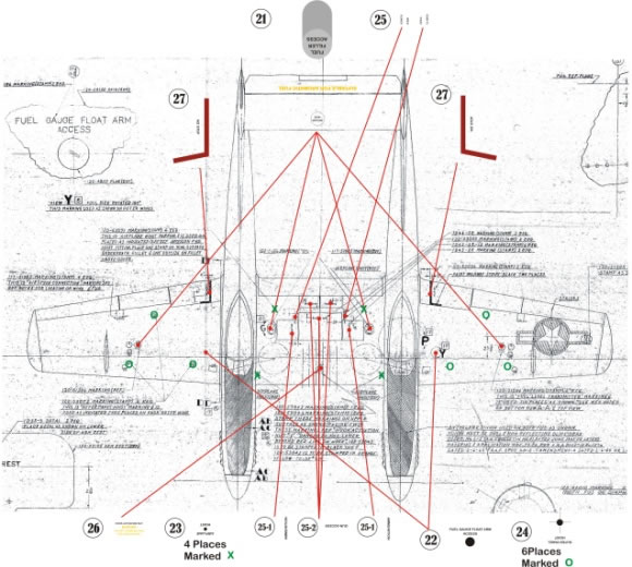
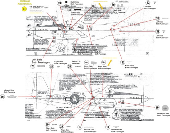
Drawings were made to show where each service marking and insignia should be located.
The research and development of this project took over 2 years. Another year was used to make masters. molds, and parts. The total assembly time for the project was about 200 hours, excluding the redesign of the masters and molds. Although a project of this type requires many processes beyond the actual assembly of the model, the research required provided many new insights to this amazing "FORGOTTEN" aircraft. Having access to the original North American Aviation drawings took me to another era where drawings boards, slide rules, and hand tools were the norm. Developing the processes required to produce parts gave rise to a new-found respect for model manufacturers and their processes.
Every modeler should attempt a "scratch" build at least once in their modeling career. Yes, it is sometime difficult, but the end result is extremely rewarding. The biggest hurdle is getting over feeling like a mosquito in a nudist colony; knowing what to do, just not where to start...
© Ken Friend 2013
This article was published on Sunday, September 15 2013; Last modified on Sunday, September 15 2013