
Williams Brothers 1/8 Wright J-5 "Whirlwind" Engine - Part 3
By Rogerio "Rato" Marczak
As mentioned in Part 2, I was looking for a different metallic color for the missing details in order to avoid a too monotone look. I took my old tin of Humbrol Metal Cote Polished Steel (#27003) and tried it on a piece of scrap. I just have forgotten how good this stuff is. It dries as a flat dark gray with a very light metallic hue. After a couple of passes with a cotton swab, the shine comes out exactly like the color name states. So I used this color for a number of smaller parts (levers, caps, and some nuts). Interestingly, because you can´t reach all depressions and recesses of some parts, the result is an attractive effect with higher areas shining and the others remaining dull (sometimes you don´t even need to polish it - the handling of the parts takes care of it). No need of washing!
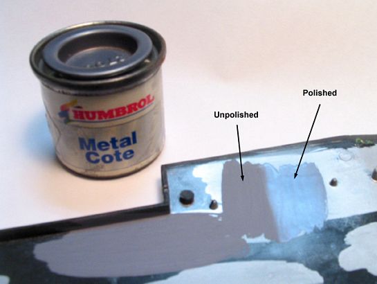
Testing Humbrol Polished Stell on a piece of scrap
Then it was time to finish off some major subassemblies. The accessory drive case was the first. After gluing the missing parts (fuel pump, oil pump and some blank-off plates), I couldn´t resist to make a very light dry-brushing using the Humbrol Polished Steel.
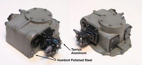
The accessory drive case finished
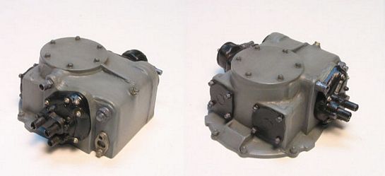
Another view
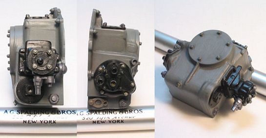
And another. I failed to find a Williams Bros. pen...
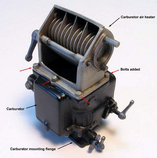
The next one was the carburetor. I painted the levers (parts #63 and #64) with Polished Steel attached them, and then gave the same treatment of the crankcase accessory drive. And by the way, these parts (the levers) don´t match their corresponding shafts. You have to enlarge their openings to make them to fit.
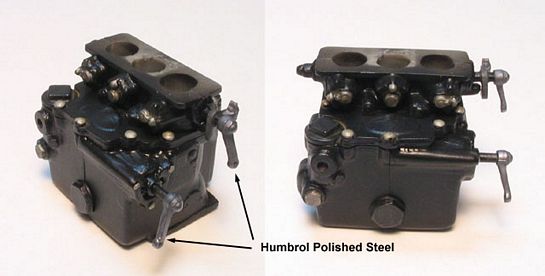
The carburetor ...
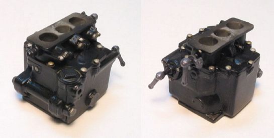
... another view
As for the carburetor air heater, I cemented six nut/studs to the lower side of the mounting flange and treated the area with a heavy wash.
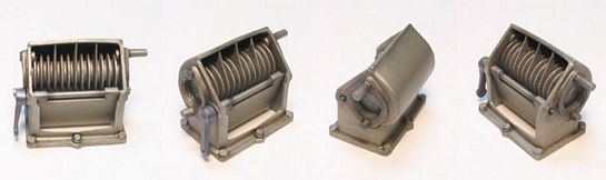
Some views of the finished air heater
The carburetor was then cemented atop the air heater. The whole set will be later butt-glued to the flat area below the intake manifold.
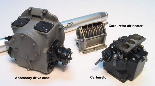
The three major subassemblies ready to be installed
Here are the carburetor and air heater put togheter
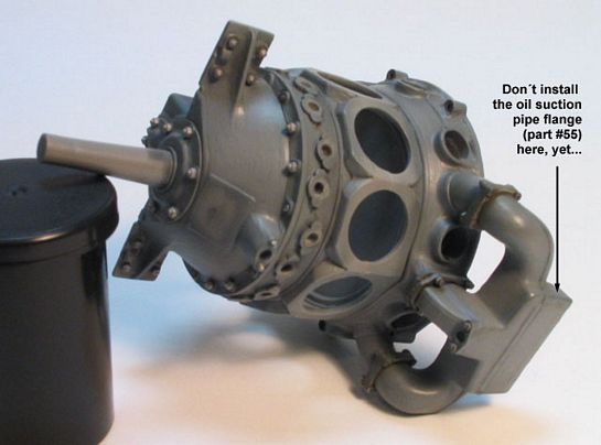
The intake manifold was installed under the intake distribution housing. It was a very problematic fitting. Even after flattening the intake ends, they didn´t match the outer and center flanges (parts #30 and #31) very well. I waited until the cement was dry and washed the area very heavily with a black/brown oil paint mixture to dissimulate the remaining gaps. Be aware that there is an oil suction pipe (part #54) connecting the drive accessory case with the base of the intake manifold. Fortunately, the pipe is attached in the holes of separate flanges (parts #55). I glued the accessory case flange in place but left the one which goes on the intake manifold for later. This will afterwards allow me to find the correct location of the intake flange using the oil pipe itself as a guide.
The accessory drive case was butt jointed to the rear of the crankcase, but the carburetor/air heater set was left to the end.
Intake manifold installed
Next, I had to install all 18 rocker boxes atop the corresponding flat spots on the cylinders. These parts must be positioned very carefully to allow each pushrod ends to touch their pad section and the rocker box simultaneously. I could choose to install the cylinders, then the pushrods, and at last the rocker boxes, but it would be almost impossible to keep a good alignment for all 18 pushrods. I started assembling the rocker boxes on one of the cylinders with regular cement. While the cement was still wet, the cylinder was dry fitted to one of the crankcase openings and the position of the rocker boxes adjusted to match the pushrods spacing. Once the glue has set, I used this cylinder as a pattern to glue all remaining rocker boxes on their cylinders.
Don´t forget that the longitudinal alignment of the rocker boxes is also critical. Since the cylinders will be mounted side by side, any deviation here will be visible. I traced some parallel lines on a piece of white paper and used it as an alignment device during this step. All you have to do is to position the cylinder so that the spark plugs remain visually aligned with one of the lines. Then, while the glue is still web, check if the rocker boxes are also parallel to other lines, and correct if necessary. They are not finished, though, as there are still the 36 arm grease fittings to be glued on the sides of the rocker boxes.
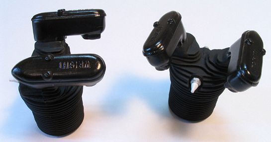
How the cylinders look with the rocker boxes installed
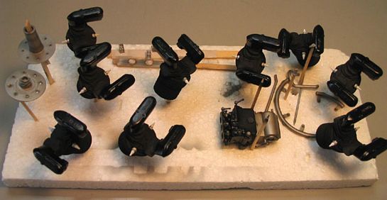
Keep them together... losing something now is fatal
At this point it become clear that the handling of the model would be a major issue. So I made a jig out of acrylic plates and installed the engine with its mount using small screws. The jig allows 360 degrees rotation so that I can reach all cylinders with the same easiness. Moreover, you can make use of gravity while the glue is setting....
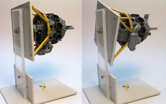
The mounting jig
now it is much better to install the stuffs.Since the kit´s rubber ignition harness loom was discarded, I removed the corresponding locating pins around the crankcase bolt ring plate. Later I will drill small holes to accept the scratchbuilt loom.
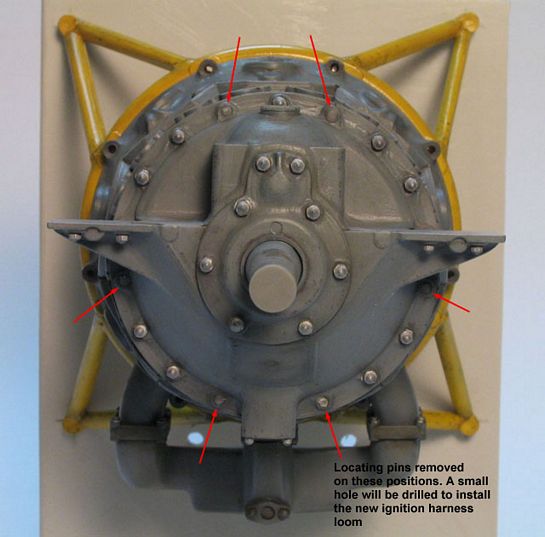
Preparing the attachment points for the new ignition harness.
I inaugurated the jig installing the cylinder bases (seats). Nothing difficult here, but a hint of the seam line remained visible between each base. Fortunately, the area will be almost invisible after the cylinders are in place. I decided not to install the cylinders now. I´m afraid they will prevent reaching some location where I forgot something... it always happen to me.
I also discovered that the magneto advance pivot rod (part #10) can´t be inserted in the hole I made! I have to enlarge the hole, but will left the part to be installed later.
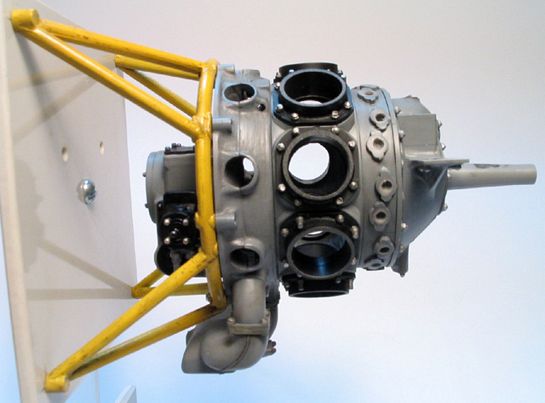
Cylinder seats installed
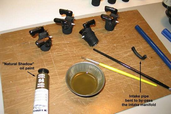
The instructions clearly mention that one of the intake pipes is made of rubber because the plastic (straight) ones won´t by-pass the intake manifold. Since I´m not going to use any rubber parts, one of the plastic intakes was bent to properly clear the intake manifold. Here is a good hint to produce very localized bents in plastic parts: I use a steam immersion-heater of an old cappuccino machine (no, it doesn´t work anymore - for cappuccinos, I mean). Just keep the part under the steam jet for some seconds and bend the part before it cools down. Watch your fingers here - steam is hot - better to hold the part with pliers. This technique works wonderfully, and enables a more precise work than immersing the whole part in hot water, because you control where the heat acts (the rest of the part remains hard).
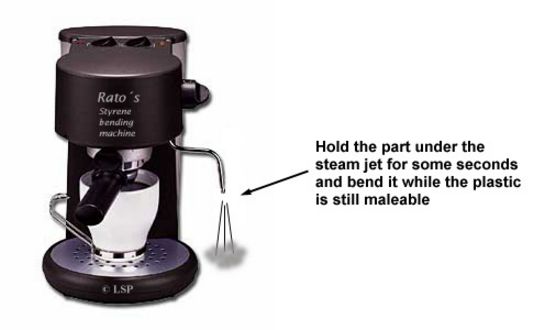
A simple way to bend plastic parts. If your equipment also delivers cappuccino even better (mine doesn´t anymore).
Before setting aside the cylinders, I washed the spark plugs area. I always waste more oil paint than the necessary trying to reach a good color tonality. A fellow modeler (who build figures) gave me a hint: a color called `Natural Shadow´. It is very good indeed. When in doubt, that seems to be the color to use....
Washing those areas looking ´too fresh´
I´m really enjoying this project. By now the part trees are empty, and this beast is starting to look like an aircraft engine.
Part 1 | Part 2 | Part 3 | Part 4 | Part 5
© Rogério ´Rato´ Marczak
This article was published on Wednesday, July 20 2011; Last modified on Saturday, May 14 2016