
Tamiya 1/32 F-15E Strike Eagle - Part 1
By Douglas Chan
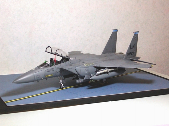
Hi guys, before I go into detail of the model, I would like to thank CC for giving me a push to make this model. I showed a photo of the Mudhen to my girl last year and asked for her opinion. Amazingly she said "it is good looking" and she would buy me a model. Woo, that was really unexpected. So, I got one and built it. Thank you CC, I love you so much !
Okay, I know you guys are bored, alright, let's get to the point.
The Kit
There are several kits available in the market. The very common and economic ones here in Hong Kong are Hasegawa and Academy in the scale of 1/48. However, these two kits are not accurate at all (bulged main landing gear doors, pylons underneath CFT, cockpit, etc.). You will need to do a lot of modification on the model.
Then it is Revell and Tamiya in the scale of 1/32. Revell is neither popular in Hong Kong. So in the scale of 1/32, the only choice is Tamiya. Fortunately, the price of 1/32 kits has dropped considerably in this two years. The kit costs only HK$400 i.e. US$51.
The box is quite big in size, so make sure you have your love one's support or you have her fully informed, because there is no way that you can sneak the big box pass her.
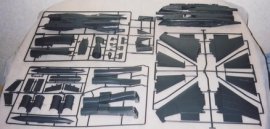
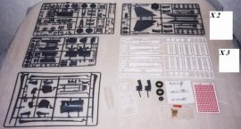
Opening the box you will see the upper and lower body; 11 sprues of plastic parts; a set of screws, nuts, rubber tires, and metal landing gears; one sprues of clear plastic parts for the canopy and navigation lights; two sheets of decal; and one piece of RBF sheet.
The instruction booklet is of A4 size, 28 pages, which is really informative for making an out-of-box kit. A better one should be the Tamiya 1/32 A6M5 Zero. Accessories I was not building the Strike Eagle in the out-of-box way. As a matter of fact, I added every add-on parts I found. These add-on parts included:
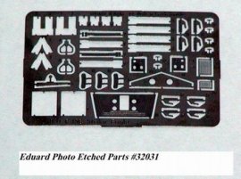
- Eduard photo etched parts # 32 031 F-15E Strike Eagle 1/32 scale detail set for Tamiya kit
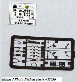
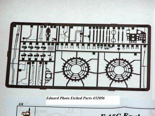
- Eduard photo etched parts # 32 056 F-15C Eagle 1/32 scale detail set for Tamiya kit
- The Gunsmoke Range, Flightpath, GBU-10C Laser Guided Bomb Set
- The Gunsmoke Range, Flightpath, 1/32nd Scale AIM-120 AMRAAM Missile Set
- The Gunsmoke Range, Flightpath, 1/32nd Scale AIM-9L/M/R/S Sidewinder Missile Set
- Clear plastic lens of 2.5mm dia. 15E04, 15E05, 15E06
Construction
Cockpit
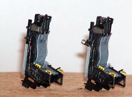
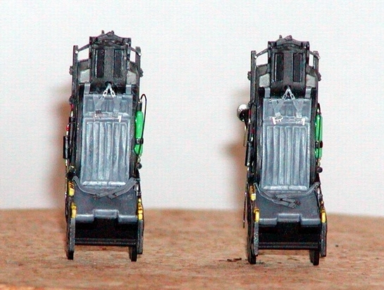
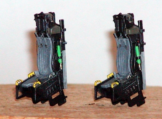
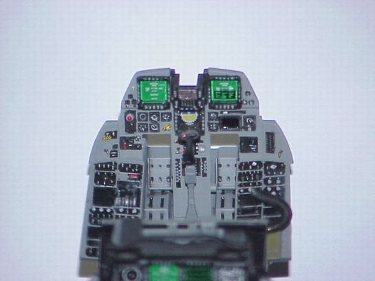
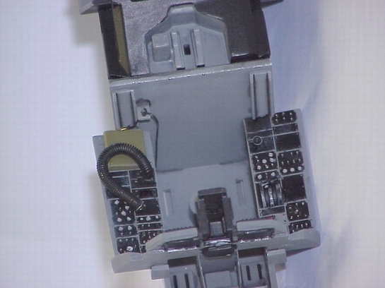
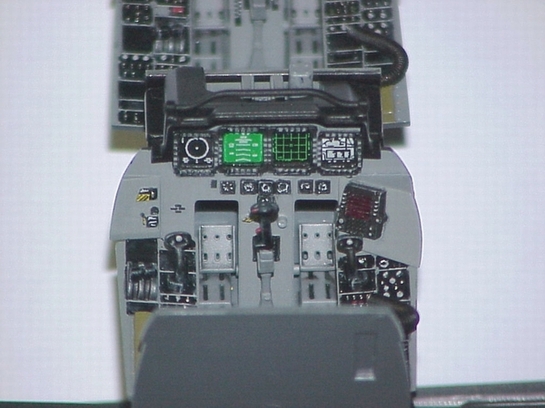
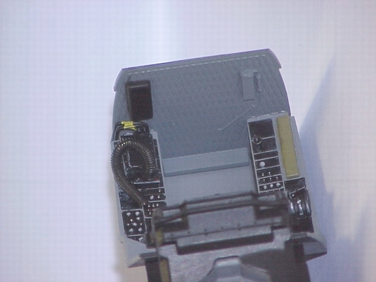
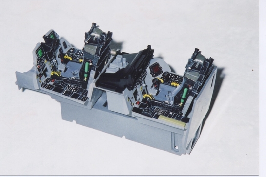
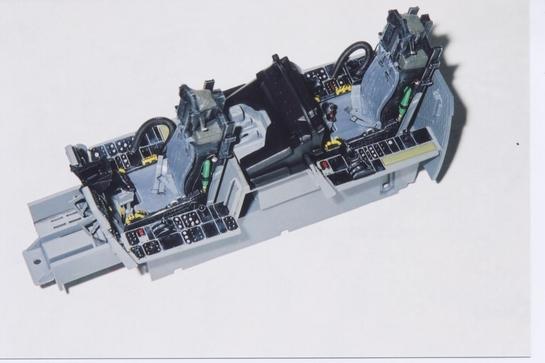
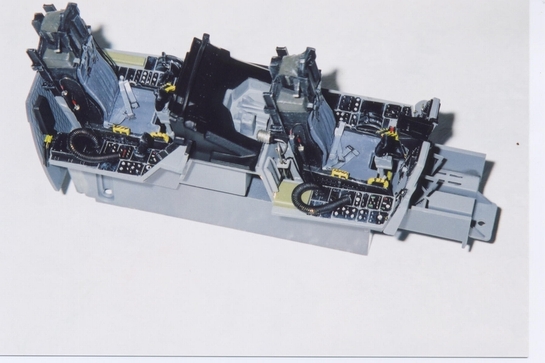
As usual in every model aircraft, the very first thing is the construction of cockpit assembly. There was no problem assembling the kit parts. The hose on both sides of the original seat was replaced by copper wire. Seat belts from Eduard set #32031 was added to the two ejection seats. Pedals and instrument panel supports from Eduard set #32031 were also added. I've scratch made the oxygen supply hoses, and the canopy lock pins in the cockpit. Also, some wiring, gas hose coupler, and structural parts were added. Reference was made to the walkaround photos in ARC and Verlinden Lock On No. 22. 15E07 to 15E17
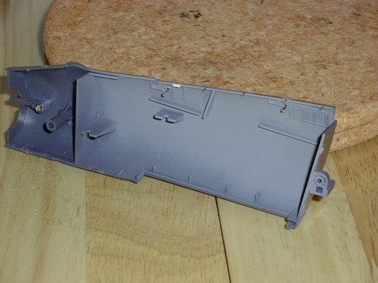
Intake Ducts
The intake ducts assembly is of upper and lower half. Once glued there was a noticeable seam in both sides of the ducts. The only way was to apply putty, let it dry for a few days, sand it until there was no seam at all.
A lot of effort will be saved if there was an after-market resin one piece intake duct. I hope one will make this available. This is one of the two critics I have on this kit.
The finished ducts were then sprayed with flat white. When it is completed dried, a sponge of appropriate length was inserted into each duct to cover the white color (make sure the one and a half inch length near the intake is uncovered). Then the body grey color was sprayed. When the grey color was completely dried, the sponge was removed. This was how I made that two tone color inside the intake duct. Sponge offered the advantage that it can be shaped easily. By using it there is no need to do the difficult masking on the inside of the duct.
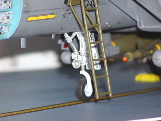
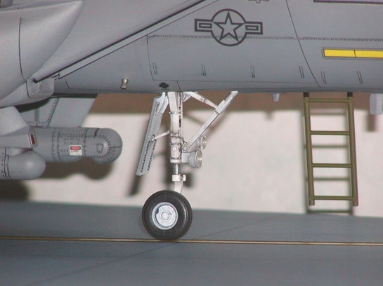
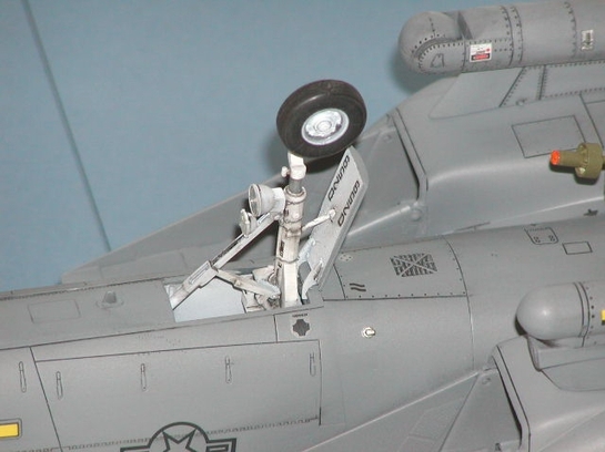
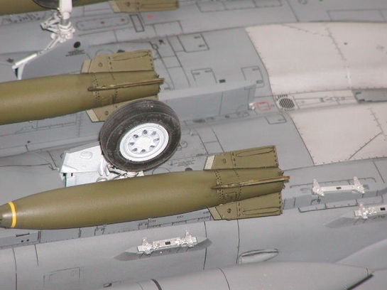
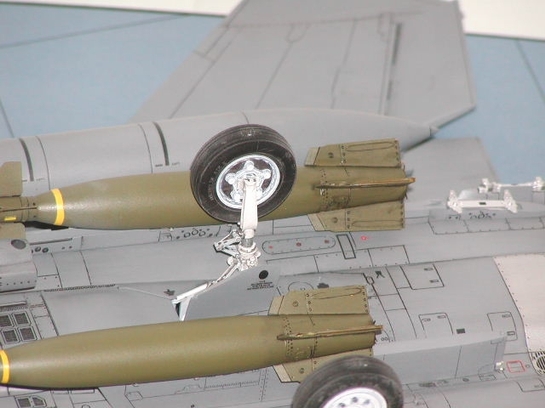
Landing Gear
The whole model is quite heavy, particularly when carrying after-market resin laser guided bombs. Therefore white metal landing gear is a must to provide a reliable support. Also, the white metal landing gears duplicated quite well of the real thing. I should have added a brake hose for the main landing gears. However, the main legs are not easily visible as the view is being blocked by the laser guided bomb. So, I gave up adding the hoses. All three landing gears were sprayed flat white and then a black color wash.
Wing/Fins
The main wings, tailerons, and vertical fins fitted quite well. A little sanding was needed but that was all. They were all sprayed with the body grey color.
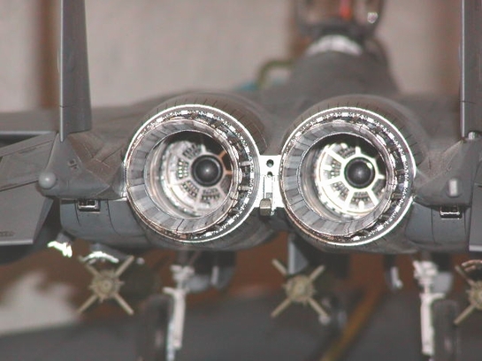
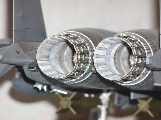
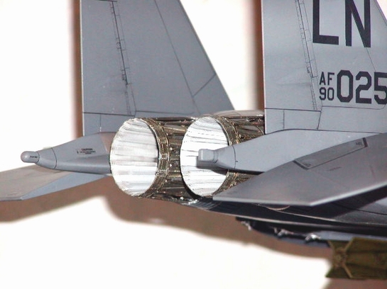
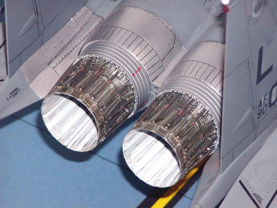
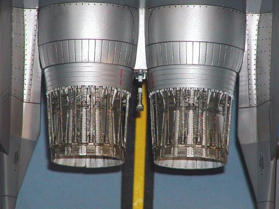
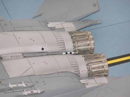
Exhaust Nozzles
Here comes my second critic. Similar to the induct ducts, the exhaust ducts are also assembled from a upper and lower half. So there were also visible seams on the inside of the part. However, because of the recess on the inside of the exhaust ducts, there was nothing I could do to cover those seams.
The exhaust nozzles fitted well. It was just a little tired to prepare the 30 identical small linkage and turnkey features. But, it was worth the effort.
The inside of the finished exhaust ducts and the exhaust nozzles were sprayed flat white. Then, a black color wash was applied for the effect. When the inside was readied, it was sealed with masking tape, and then the external was sprayed with a mix of metallic grey and clear orange. A dry brush of silver was applied.
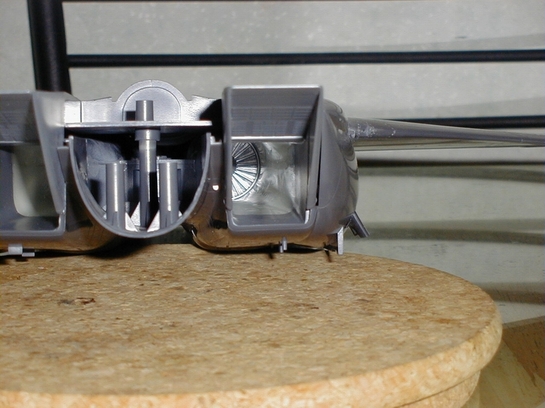
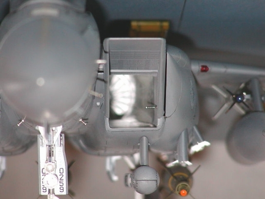
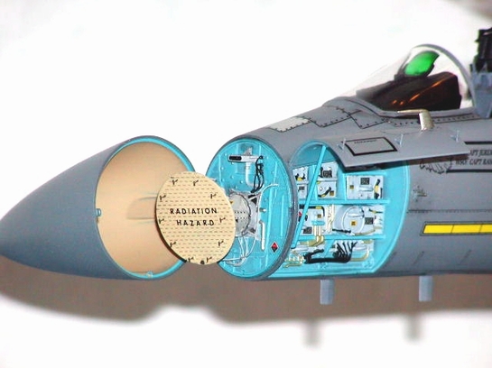
Radar
The radar assembly also fitted well. However I did a modification on the radar disk and the support structure. First the plastic antenna on the radar disk were removed, the radar disk was then sprayed with Dark Yellow, then the letters "RADIATION HAZARD" were transferred, the photo etched T-shape antenna from the Eduard set #32056 were fixed onto the radar disk by CA glue. Then the wiring around the radar support structure were added by copper wire. After the application of decals and wash, the assembly looked quite realistic.
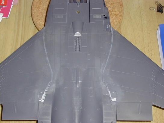
Body
After the installation of the intake ducts onto the lower body, the upper body was fixed to build up the main body. Because of the variable intake, extra care was taken, particularly while the forward portion of the CFT was glued. CA glue was used to save time for curing. Then the forward fuselage was attached to the main body. Only little putty was needed for the joint, I was quite satisfied with the result, bear in mind that the model is quite big in size. After that, the wings were attached to the main body. Again, CA glue was used. For the wing joint, putty was not necessary. The cured CA glue already served the same purpose. So I sanded it and it was finished. Holes of dia. 0.5mm were also drilled on the body to simulate screw marks. Panel lines removed were re-inscribed.
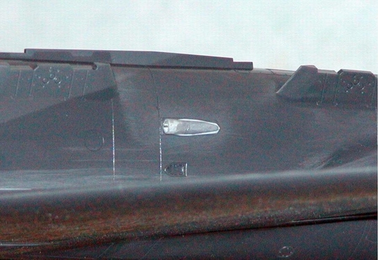
There should be an air vent near the wing joint. It is strange that Tamiya missed this part. By the time I built this kit, I had to scratch built this little part. I used a 3 mm tube, pressed to oval shape, then attached it to a strip. A small photo etched plate is inserted inside the oval tube as it should look like in the real thing. However, we now have the add-on part from Cutting Edge Modelwork.
© Douglas Chan 2002
This article was published on Wednesday, July 20 2011; Last modified on Saturday, May 14 2016