
How To Build An FGR in 1/32 Scale - Part 1
By Frank Mitchell
How To Build An FGR in 1/32 Scale;
A Further Stop On the Continuing Quest
Part 1: The Rear Fuselage
by Frank Mitchell
The British FGR version of the Phantom has long been an enigma for lovers of 1/32 scale. After several involvements in the attempt to build an accurate one (including the long-gone Wild Hare kit), I finally decided to try and put together a decent description of a conversion from the Tamiya F-4. All this looks a bit lengthy and wordy, but bear with me and all will be revealed. The end result will be, I hope, a reasonably accurate FGR, with a correct span and tread. It is also inexpensive (if you don't count the Tamiya kit) and relatively easy to build.
I must make clear that this is not intended to be THE way to do this; it is MY way, based on building a couple of these beasts, but I make no claims of absolute accuracy; all I can say is that appears to match all the dimensions and photos I have. I also have no idea how well these steps would work with the Revell kit.
A couple of notes before we begin:
A. After much study of this bird, I think I have decided, to my satisfaction at least, that the fuselage of the FGR, from about mid-wing to the exhaust, is basically the same width as the F-4. I think this is borne out by the relationship of the flaps to the fuselage, among other things. The main difference is that the sides of the fuselage do not curve in behind the wing, as do the sides of the F-4, to meet the burner cans, and the area between the cans is somewhat modified from the F-4. Obviously, the intakes are increased in size and do overlap the wing to a greater degree than on the F-4; this will be tackled in Part 2.
B. This model is an experiment; while it is based on the experience of the previous two I have built (one the Wild Hare kit), there are a few things that did not go as planned the first time around, and the careful observer will note these as we go. In addition, I guess I should note that a large percentage of this model is composed of parts left over from mine or friends' previous projects; you might therefore, see some putty or unnecessary cuts in the photos. Ignore them---
C. A package of commercial 3/16 X 1/16" styrene strips will be very handy for this build. They are consistent, offer enough thickness for gluing, and the width is perfect for most of the changes.
With that said, away we go:
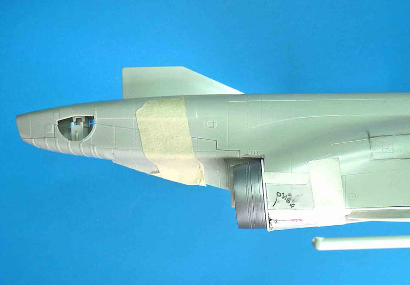
Pic 1 shows where we are beginning; a stock Tamiya F-4J. Note the way the fuselage sides curve inward; that is our point of attack.
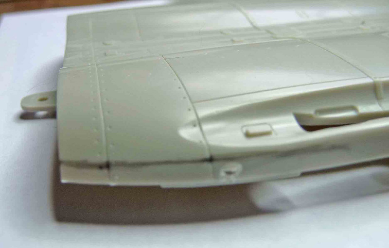
On the LOWER fuselage, draw a line about 3/32 below the upper edge of the rear outboard fuselage sides (behind the wing). This should extend from the rear edge of the fuselage forward about 1 11/16".
Carefully saw a slit along the drawn line, trying to keep the cut as near to horizontal as possible (this will help later gluing).
Saw a vertical cut to remove this rectangle.
Although the following dimensions aren't absolute, cut two pieces of 3/16" strip styrene to a length maybe a ¼" beyond the end of the fuselage.
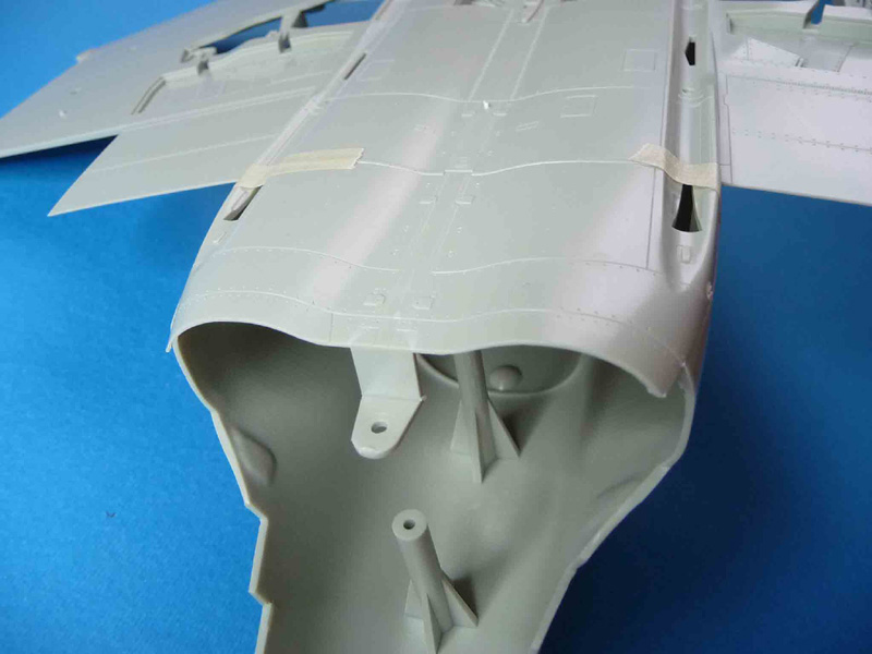
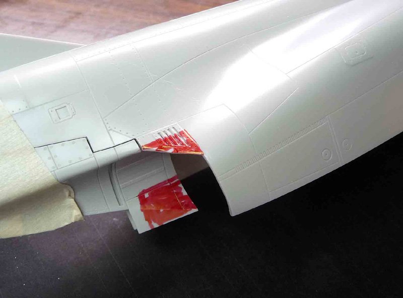
Using two sets of pliers (or your fingers), twist this piece so that it will fit into the cutout, but also roughly follow the curve of the exhausts (this is also not critical; there will be lots of opportunity to correct any discrepancies). Glue in place as shown.
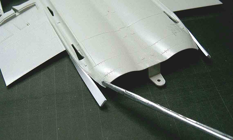
Using needlenose pliers (or a hemostat), bend the outer edge of the fuselage exhaust opening outward to roughly match the twisted piece.
Cut a thinner piece of styrene (maybe .020 - .030) to a rough triangular shape and use it to fill in the space as shown in the photos. I also added some stretched sprue pieces to reinforce the joints.
You should now have a fuselage that no longer curves in, but follows the straight line of the fuselage.
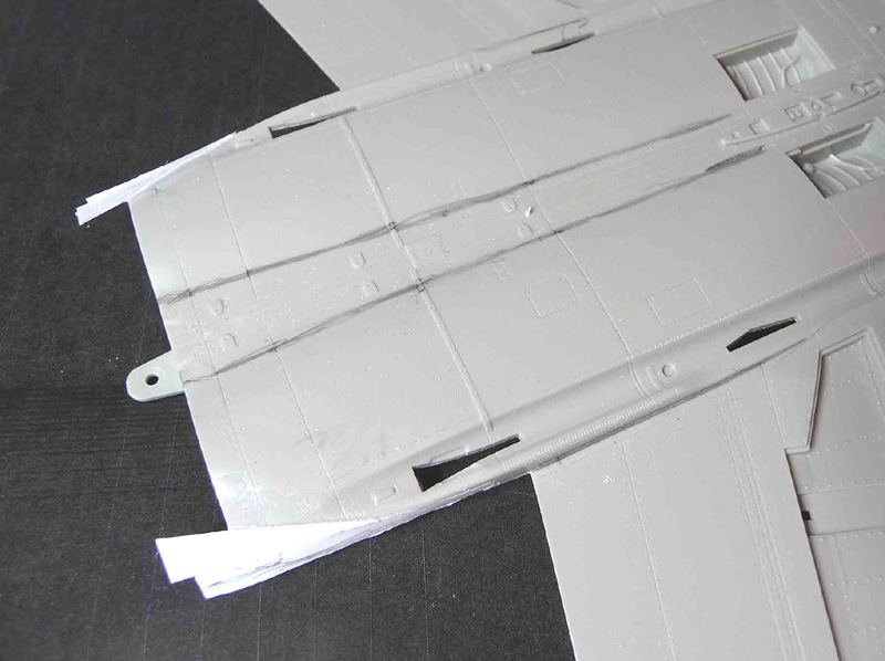
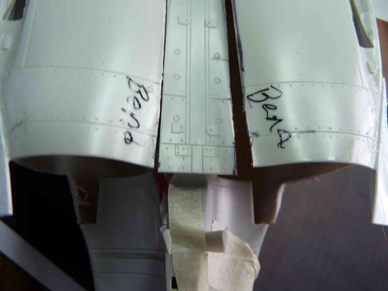
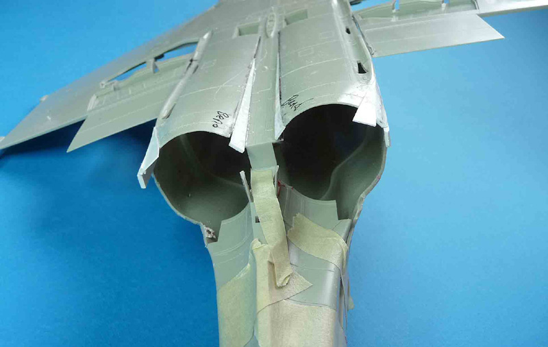
Saw four slits: two along the flap/fuselage junction, and two along the natural junction of the bottom fuselage and the engine bulges (The black lines seen in Pic 6w).
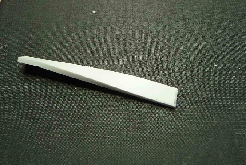
Make two triangular wedges of the 3/16" strip that are tapered down to about 4 3/8" long
Glue these "wedges" along the top edge of the modified outer fuselage edge. Photo 8 above should make this clear. Now, using your fingers, grab the lower engine area just behind the auxiliary intakes and gently bend the fuselage downward until they make a straight line along the top edge.
You should now have a nicely angled-downward exhaust area.
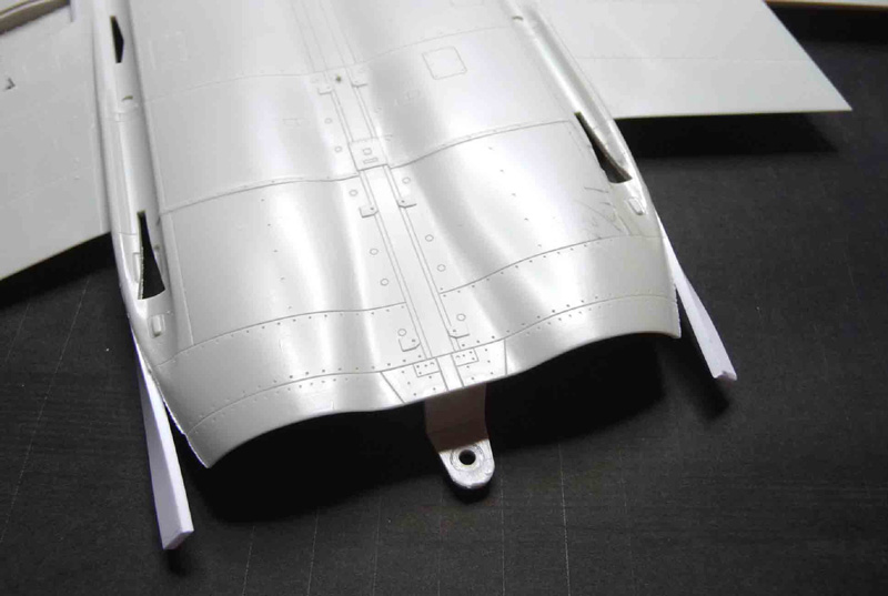
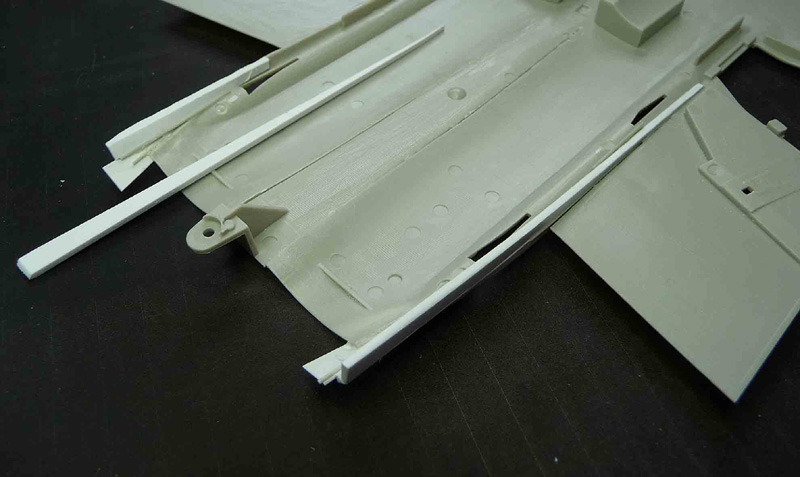
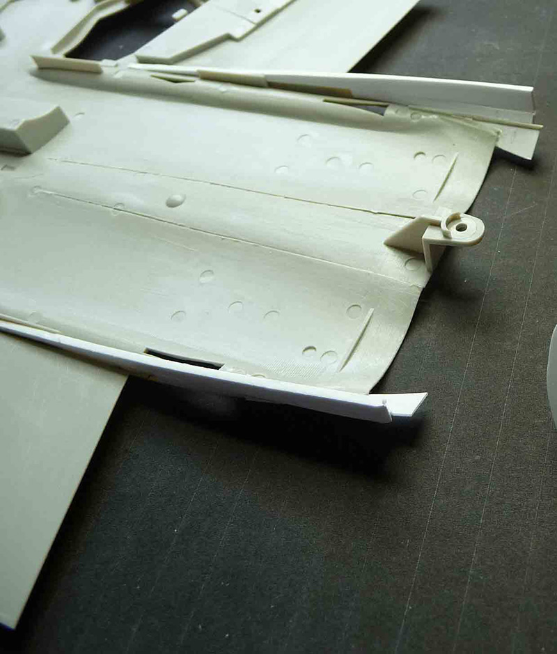
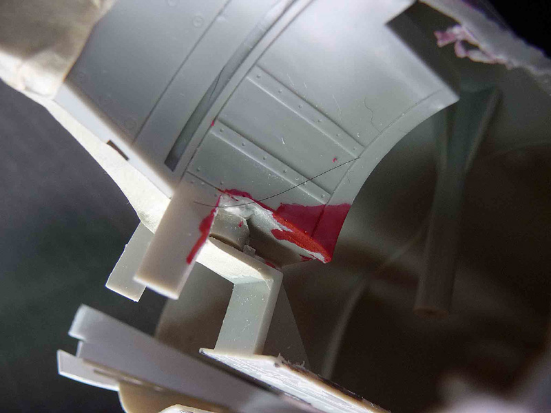
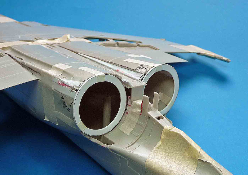
On the kit LOWER REAR FUSELAGE section (behind the exhaust openings), remove the areas shown in red in Pics 9 and 10. That will allow clearance for the burner cans.
Using a needle nose or round-jawed pliers, bend out the sides of the inner engine bulges so that they follow a straight line.
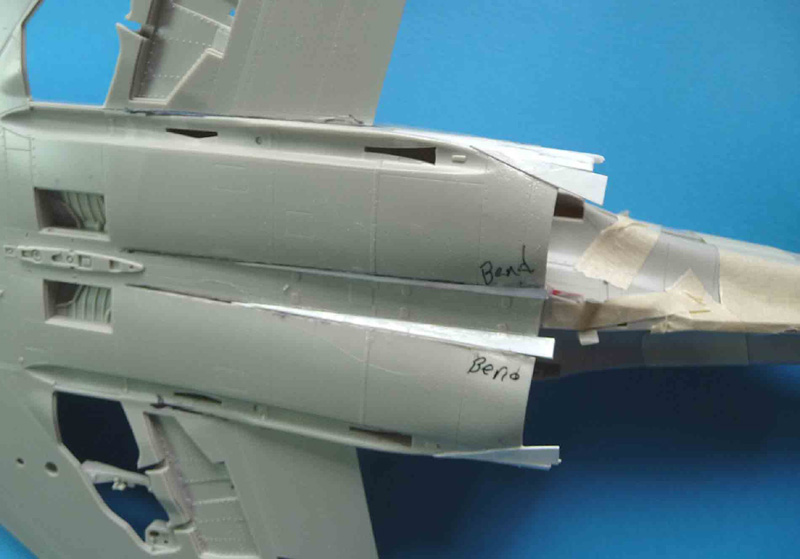
Now fill the resulting triangular space with wedges of the thinner styrene (roughly about 3/16" by 3 1/8").
You should now be able to tape the upper and lower fuselage parts, and the rear fuselage section tightly together and have an FGR within sight.
From here on, the construction is somewhat dependent on what you will use for burner cans. I will describe what I did, and I do think it should work for most any solution someone comes up with only because I am fairly confident in the dimensions of my cans (Does that sound bad?).
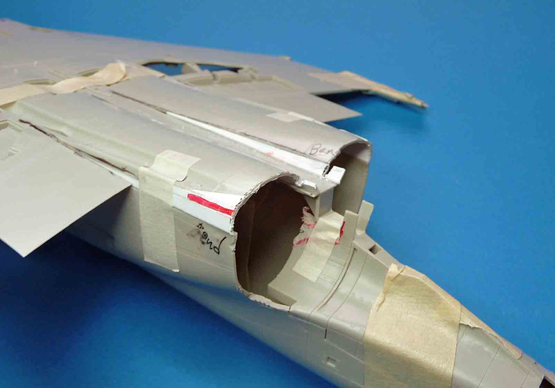
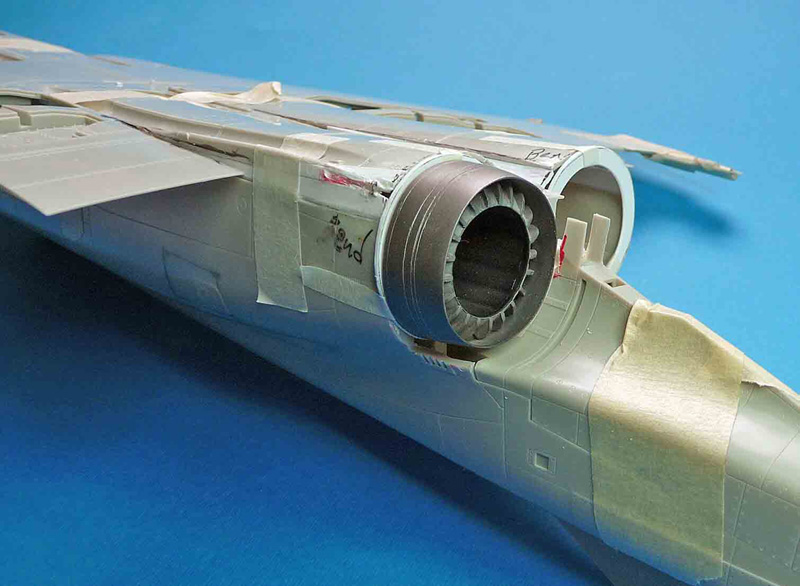
I used the Tamiya inner exhaust parts, to which I glued the new cans. Therefore, I cut two circles, the inner diameter of which is the diameter of the Tamiya parts when glued together (1 1/32); the outer is the outer diameter of the burners (1 5/16"). (Pic 14 below). As can be seen in the photo, these rings will be the true interface between the cans and the fuselage.
To fit the rings:
Trim off the excess length of the added pieces at the black line in Pic 14w, which is actually the rear edge of the kit fuselage half.
Then:
Make a couple of wide-ish slits at the lower outside corner of the new area and, while holding them together apply supper glue to make them secure (Pic 15). Do not glue fingers to model.
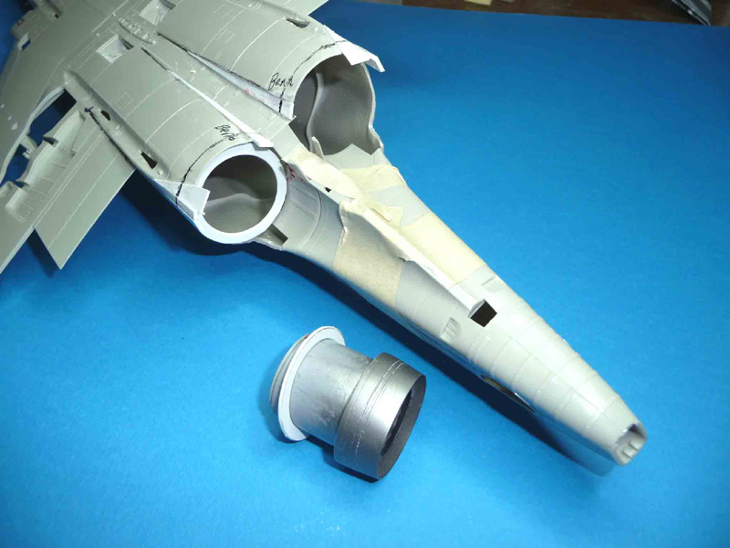
Tape the rings into place (as best they will fit at this point.
I used a burner from one of my previous FGRs to demonstrate how all this is beginning to come together.
Because all my interior work has yet to be done, I do not have pictures of the following, but it is straightforward.
Using the putty of your choice smooth and blend in everything that we have done up to this point. I much prefer and strongly recommend using one of the 2-part epoxy putties/sculpting pastes for this; my personal choice is a SIG product, Epoxolite, but there are many others around. Don't be surprised if you need to make a small slice here and there to make everything fit properly; this work was not done by a computer-controlled machine; at least, I don't think I am. Yet.
One final note: I did not touch on the vents in and around the new exhausts. Here, you are on your own. I will note however, that on a number of similar situations, I have simply used decals made on the computer (lots of I's and l's), and very few, if any, have noticed that they aren't real. Such a technique also assures that they will be equal in size and width, and will not take fours days each to accomplish. Likewise, no mention was made of scribing modified panel lines, etc.
This concludes Part 1. Part 2 will deal with the Intakes, and maybe, if I am feeling particularly ambitious, there might be a Part 3 that will deal with the burner cans. Maybe.
Part 1 | Part 2
© Frank Mitchell
This article was published on Wednesday, July 20 2011; Last modified on Saturday, May 14 2016