
A Sea Harrier in 24th Scale – The Hard Way
By Frank Mitchell
It is an immutable fact of modeling life that all that is required to make sure that a given kit is produced is to build one from scratch or as a major conversion. My most recent case on point: A 24th scale Sea Harrier, which was finished a bit less than three months before the Airfix kit was announced. I decided to go ahead and write the thing up just because I felt sorry for it, and for what it might be worth as a study in techniques.
I elected to build the first production version of the Sea Harrier, the FRS-1, primarily because it earned so much fame and praise during the war that erupted over the Falklands Islands (or Maldives, if you prefer) in 1982. Choosing that version also meant that the markings would be much easier. Besides, I think it is better looking than either the RAF early versions or the later FRS-2 Sea Harrier, which had a more bulbous nose and lengthened rear fuselage.
The first problem was references. At the time, I had assumed that there was a lot of information available on the Sea Harrier, and there is, but for someone trying to build the original version, getting good detail pictures was not as easy as it first appeared. The best references were two 1983 articles (May and July) from the British publication Scale Models, which dealt specifically with the Falklands aircraft and contained a nice set of drawings, and Aeroguide No. 3, Sea Harrier, published in 1984, which contains many detail photographs.
After enlarging the drawings to 24th scale, I found that I could cut the nose from the kit fuselage halves, move it forward with extension pieces of plastic card, and use that structure to build up the sides of the fuselage to the shape of the Sea Harrier’s forward section.
The outline of the extended cockpit area was drawn on the plans, and pieces of styrene were cut to create the proper line between the windscreen and the rearmost point of the new canopy shape.
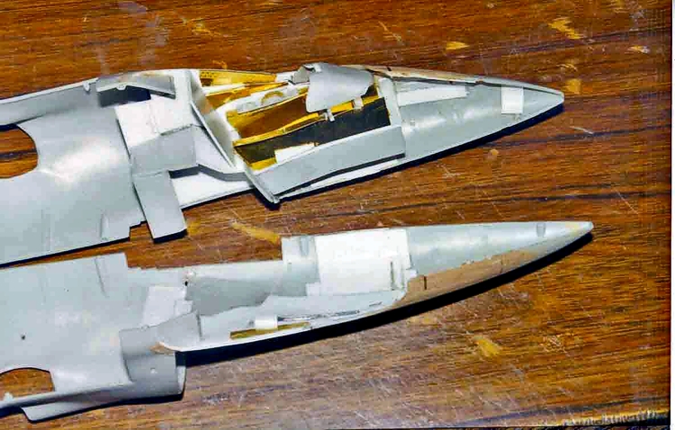
Epoxy putty was used to fill in gaps and create the final contours of the forward fuselage, after which work began on the interior. Since the cockpit of the Sea Harrier was significantly different from the RAF Harrier, a good deal of scratch building was necessary. Styrene was used to modify the nosewheel well, the cockpit floor, and the rear wall. Thin styrene was glued onto the sides of the cockpit to cover the lengthening structure and create a smooth base on which to add cockpit details. A Flightpath brass upgrade set for the Harrier kit supplied the interior consoles, portions of the walls and some other small pieces of the cockpit. A piece of clear acrylic was also inserted into the right side of the nose to represent the camera port. The instrument panel, most of the consoles, the area to the rear of the seat, had to be scratch-built and detailed as necessary. The ejection seat also had to be scratch-built. That was done by using the dimensions of the kit seat and making up a new styrene structure. The parachute and cushions were made from balsa covered with facial tissue and painted. Linkages and other small parts were made from styrene, wire, etc.
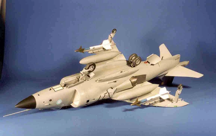
This model is both big and heavy, and proper (and sturdy) assembly is of great importance.
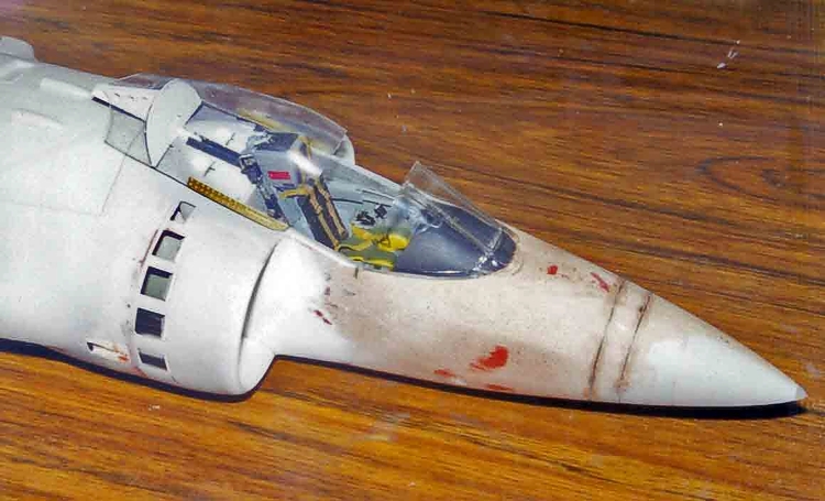
One of the problem areas of the Airfix Harrier kit is the auxiliary intake doors (or lack of them) in the engine inlets. They are only vaguely outlined and do not even suggest the wide-open appearance of the doors on the real aircraft. There really is no alternative but to cut out doors in the top half of each intake and replace them with new doors in the open position. It is a bit fiddly to do, but the appearance is certainly worth the effort. At least the intakes are supplied as two-piece separate units, so the job is not as bad as it could be. The doors in the bottom of the intakes were just scribed in since they are closed by gravity. Once the intake doors were complete, the front face of the engine was painted and detailed. The engine itself was only roughly assembled since it would not be seen. Its only purposes are to serve as a mounting point for the engine face and exhausts, and to add strength to the fuselage.
While the windscreen is the same as used in the RAF Harrier, the canopy is quite a different shape, being somewhat deeper and more rounded at the rear. A mold was made by first filling the kit canopy with patching plaster. This was removed from the canopy and allowed to dry for 24 hours. To stabilize the plaster, the surface was covered with thin cyanoacrylate. The modifications were made both by sanding the plaster and by adding and shaping pieces of soft balsa with CA. The mold was then covered with 2 coats of 20-minute epoxy, which was sanded and polished. The new canopy was formed from clear vinyl by the heat-and-smash method. The structure in the rear of the canopy was built from styrene along with some photoetch from the Flightpath kit. Circular sections were sanded into the edge of the rear canopy to represent the cut-outs needed to clear the two antennas mounted on the top surface of the fuselage.
The vertical tail had to be extended to house the forward part of the RWR. The RWR itself was cut from a mahogany scrap and glued into place, after which the fin was sanded to final shape and scribed.
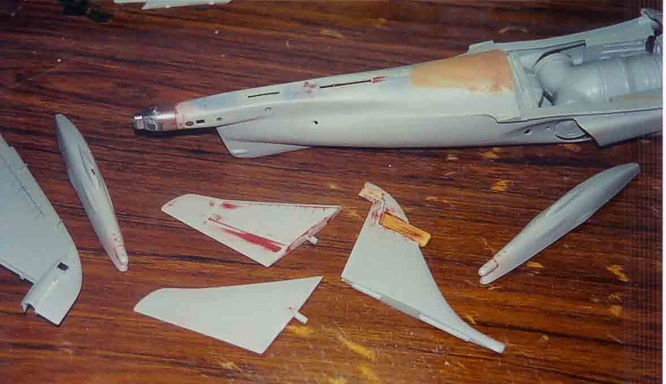
The rear RWR, which is part of the extended rear fuselage, was a white metal piece supplied in the Flightpath set. That was glued into placed and putty added where necessary. Some small pieces of photoetch were also added to that area (These modifications to the rear fuselage and fin will not be necessary if one is using the GR-3 version of the Harrier kit). The “horizontal” stabilizers were assembled and detailed with photoetch. Photo 6 shows the completed empennage and cannon.
The Flightpath set supplied a new nose landing gear, and this was used along with a fair amount of photoetch. The angle of the fork of the nose gear was altered somewhat to give a better “sit” to the model.
The main gear leg was from the Airfix kit with some detailing added.
The main wheels supplied by Airfix were inaccurate. The Flightpath instructions suggested that nose wheels be used on the main legs after applying photo-etch from their kit. Since no additional wheels were included, I made an RTV mold and cast two new nose wheels from resin. These were detailed and, although the Airfix tire wheel openings are a bit too big, when painted and detailed they were acceptable and certainly looked more accurate than the Airfix-supplied items.
Molds for a number of small scoops around the aircraft were sanded from soft balsa and thin plastic, heated over a candle, was used to form the scoops.
The airbrake had considerable photoetch added and an actuating strut was made up from aluminum tubing. A number of surface intakes and outlets in the fuselage were drilled out and tubing added to create depth. Antennas were made from plastic strip and brass wire was inserted into their bases so that they could be painted and added at final assembly. The kit-supplied Aden Cannon were detailed but otherwise used as supplied by Airfix.
The anti-collision lights were formed from old toothbrush handles and had brass wire inserted to attach them to the fuselage.
The windscreen was attached to the fuselage and gaps were filed using putty that was blackened with paint so that the putty’s bright orange color would not show through from the inside. Once that was done, the final detailing of the canopy rails was completed. From this point forward, the model was built pretty much as described in the instructions, except for the addition of details and small accuracy changes.
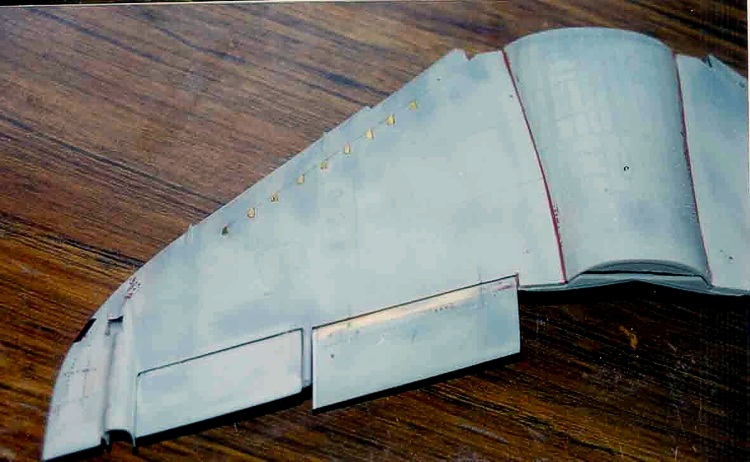
The wing was detailed by cutting out and lowering the flaps, adding fuel dump tubes to the small trailing edge pieces between the aileron and flap, adding navigation lights using toothbrush handles, etc. The most tedious job was the careful removal of the molded vortex generators and replacing them with Flightpath photoetch. A couple of thin styrene jigs were made to insure that the generators would be straight and evenly spaced. The order was also important because they get smaller towards the tip of the wing See photo).
The wing-fuselage join is not the best and requires careful trial-and-fit work if you want to keep as much of the surface detail as possible. The engine hatch was a part of this area and had to be worked at the same time as the wing. Patience and judicious sanding will achieve the desired result. I should note here that, having looked at a lot pictures of Harriers over the years, I have noticed that the panel line gaps on the real airplane, particularly around the wing/engine hatch, can leave a bit to be desired, so I did not really strive to achieve perfection. Even so, some patience is necessary.
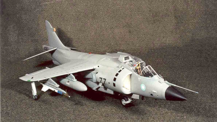
The usual underwing load on the Falklands aircraft was drop tanks and Sidewinder missiles. The Airfix-supplied inboard pylons needed to have styrene added to the forward edge so that they could be reshaped to the form used on the Sea Harrier. The drop tanks just needed some scribing.
The outboard pylons were the correct shape, but the adapters that hold the Sidewinder launching rails to the pylons had to be formed from hardwood. The sidewinders themselves were composed of white metal bodies and photoetch rear tailfins from the Flightpath kit. I elected to make my own forward fins from styrene. Because the metal bodies make the missile very heavy, the completed missiles required careful handling to avoid breaking off the fins. Their weight also meant that some extra precautions in the form of pinning all components with brass wire were necessary to make sure that the missiles would be securely mounted to the pylon and that the pylon would be securely mounted to the wing.
The small outrigger landing gear near the tips of the wing were modified by replacing the sliding portion with aluminum tubing and the outer casings were modified to accept the tubing. This not only looked more accurate, it also allows adjustments to be made during final assembly to make sure that all the wheels touch. Some detailing was carried out with photoetch and wire.
The component parts of all my models are primed separately with automotive lacquer primer, with all assembly edges masked off. Putty is applied as necessary and the parts are re-primed and re-scribed until I am satisfied. Assembly of the major components is then done, which leaves only the areas around the glue joints to deal with. This sequence makes it easier to assure that all the little dings and scratches are removed, and to minimize the handling of the more complete model. In other words, I like to leave the model as disassembled as possible during final painting and decaling. With a large model like the Sea Harrier, that approach is almost mandatory.
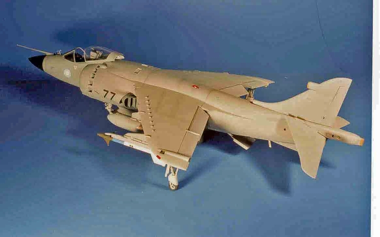
I applied the paint scheme of many of the Falklands Sea Harriers, which was Medium Sea Gray over most of the aircraft, with Barley gray on the wing and tail undersurfaces. I used Gunze acrylic paints throughout with an overcoat of Future floor wax.
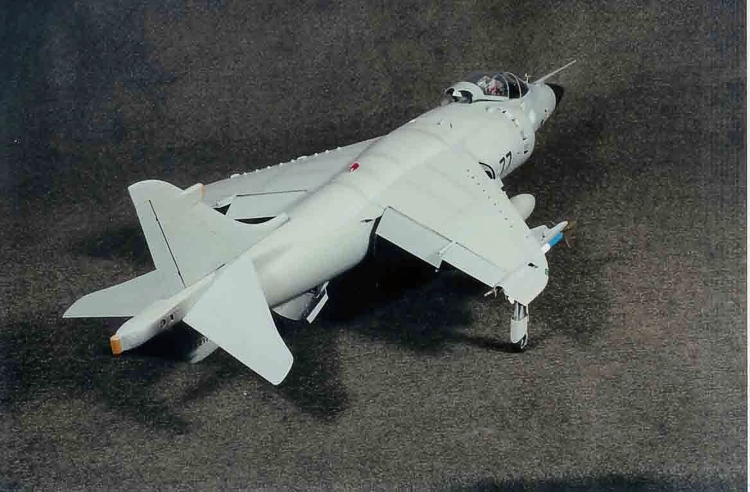
A major advantage of the Medium Sea Gray/Barley Gray paint scheme is that nearly all the markings, maintenance instructions, etc., were over painted due to the haste in getting the aircraft ready to go to the South Atlantic. This eliminates the problems in either having to paint markings or try to find others that would work, which is not easy in 24th scale. The only markings, in fact, were pale blue/pink roundels on the forward fuselage, an aircraft number on the intakes, and a small serial number on the ventral fin at the extreme rear of the fuselage. A few Rescue markings and ejection seat triangles in medium gray were found in the scrap box. The larger numbers on the intakes were cut from flat black decal sheet.
After the few decals were applied, I used a mix of Testor’s Gloss-Coat and Dull-Coat to obtain the desired variations of sheen.
To alleviate the monotone appearance, mild weathering was applied using airbrushed darker grays and pastels.
The missiles were painted white, mid- blue and olive drab.
Final assembly was carried out using Cyanoacrylate and white glue. This thing is heavy, so care in final assembly is mandatory. Future was applied to the clear parts as a finishing touch...
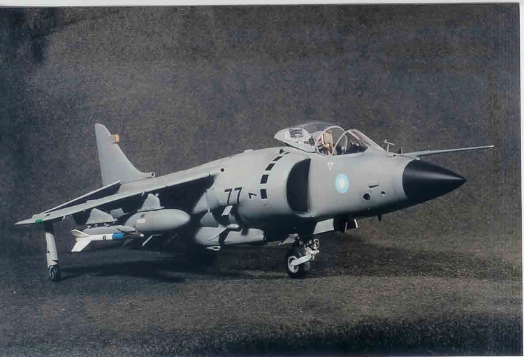
The finished model is large, but I think these 24th scale aircraft have a presence that just cannot be found in other scales. They are also very satisfying to build, even if I suffered the fate of having a kit of the Sea Harrier announced after mine was finished. This is only one of the “joys” of modeling.
© Frank Mitchell
This article was published on Wednesday, July 20 2011; Last modified on Saturday, May 14 2016