
Combat Models F9F-5 Panther
By Howard Weaver
I have always liked the looks of the F9F panther. It was used extensively in the Korean conflict and has really beautiful lines and I always wanted to model one in 1/32 scale, my scale, but unfortunately no model company ever produced one as an injected molded plastic kit in 1/32scale. Then I discovered 'Combat Models' vacuum formed kits. They made a vac kit of a Grumman F9F-5, just what I wanted. One word here about the kit. It doesn't have very much detail, no landing gear or cockpit interior, no decals, but the overall shape is accurate. The first thing I had to decide was how I wanted to display the model. First I wanted the landing gear down, the flaps lowered, the canopy open, and the nose cone openable to be able to expose the gun bay. When discussing my plans with a friend, he informed me that on the Panther, when the flaps were lowered a certain amount, the leading wing slats also automatically dropped. This was what was known as the 'droop snoot effect'. So now I had to drop the slats too!
So now a little pre-planning was in order. As with most vac kits, you need to engineer in a few things of your own. For instance, there isn't anything to mount the main landing gear into, or the nose gear either, so as normal assembly proceeds, I installed basswood blocks, glued to the upper wing skins so I could later drill holes in them to insert my scratchbuilt main landing gear into. The same holds true with the nose gear, but since I wanted the nose cone to be operable, this was done a little differently and would be accomplished after the nose was cut off. Assembly proceeds as with most vac models. I installed 1/4¨ thick balsa wood fuselage formers every 2¨ or so into the fuselage so it wouldn't collapse during subsequent handling and assembly. The rear cockpit bulkhead is also installed at this time. The wings were assembled and set aside until after the fuselage was completed. Now is white knuckle and teeth gritting time. I had to cut that nose off and separate it from the rest of the fuselage!
After the nose was cut off, I used a new sheet of 320 grit wet or dry emery paper on a piece of glass, and sanded the two mating surfaces lightly until they were flush with each other and square. I used the nose cone to scribe out and make two 1/16¨ thick aluminum formers that would be inserted into the nose cone and the fuselage. These formers were clamped together, cut out with a scroll saw and sanded smooth so that they matched each other exactly and would just slide snugly into the openings. Two 1/8¨ holes were drilled into the lower edges of the formers while still clamped together to assure that they would be aligned with each other. These two holes will be the points where the nose cone slides will be positioned. Now the cockpit floor and side consoles were made from styrene sheet and glued in place. Next the nose gear wheel well was fabricated and installed. I now installed the wings to the fuselage after finishing the air intakes with basswood and fairing them in with putty. The reason the wings are added at this point is to be able to check the balance of the model. By supporting the model at the points where the main landing gear will be installed, you can tell if it will be tail heavy or not. I found it was extremely tail heavy, so I started cutting lengths of 1/8¨ solder and inserting them into the cavities where the side consoles were made. I didn't weigh the solder sticks, but I found that the console cavities were almost completely filled up. Now I carved a piece of basswood to fit into the space just above the nose gear well and the cockpit floor and epoxied it into place. This piece of wood will be used to anchor the nose wheel and the nosecone slide mechanism. I was careful to recess the side consoles, the cockpit floor, and the basswood block, back into the fuselage opening enough to allow room for the front aluminum bulkhead to be installed.
Now I took the aluminum fuselage former and carefully drilled out the two holes to 5/32¨. Next the former was superglued into place in the fuselage nose. After sufficient curing time, the two 5/32? holes were re-drilled through their openings and into the basswood blocks. Actually I drilled the two holes completely through the blocks. Next I cut two pieces of 5/32¨ O.D. brass telescoping tubing 3/4¨ long and glued them into the holes with Elmers White glue. Two 1/8¨ pieces of tubing 2¨ long were inserted into the holes being careful not to get any glue on them. Now the other former for the nosecone was positioned over the ends of the 1/8¨ tubing and this was set aside to dry. If done correctly, after the white glue has dried completely, the nosecone former will be free to move in and out on the 1/8¨ rails! Now the aluminum nosecone former's center was cut out with a scroll saw and finished with small files. This cutout needs to be sufficiently large enough to clear the guns and ammunition boxes when they are made and installed. Now the nosecone skin is superglued over the nosecone former. You should be able to slide the nose onto the two rails and back against the fuselage and it should match the outside contours very closely with just minor sanding.
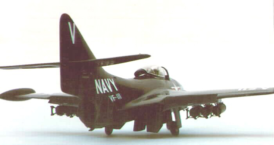
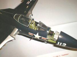
There were several gun bay arrangements on Panthers. Not so much the arrangements of the guns themselves, but how the ammunition stowage was arranged. After studying photos and drawings I decided to do the arrangement shown in these photos. The four 20 m.m. guns were scratchbuilt from 5/32¨, 1/8¨, and 1/16¨ brass telescoping tubing and would be installed onto a plastic shelf that was superglued to the fuselage bulkhead above the two 1/8¨ rails, leaving sufficient room for the nosecone former to slide underneath the shelf. Four 1/8¨ O.D. blast tubes were installed into the nosecone. The nosecone was positioned on the rails and each gun was installed one at a time making sure that each was aligned into it's respective blast tube. Done one at a time and carefully aligned insures freedom of movement of the nosecone from open to closed. Each gun was positioned so that each muzzle protrudes out of it's blast tube when the nosecone is closed. Next a second shelf was made and installed over the guns. Two ammo boxes were fabricated and installed on this shelf. On the arrangement I used, two guns were fed from these boxes and two guns were fed from under the cockpit floor. They all used mechanical power drivers to feed belted rounds to each gun. These were scratchbuilt and installed. Now that the fun part is over, the flaps were lowered and the leading edge slats were dropped. The wingtip tanks were glued together and installed and the wheel wells were opened, boxed in and detailed. The stabilizers and elevators were added now and the opening for the tailpipe was cut out, a tailpipe made and installed. An arrestor hook was made from brass rod and the tail skid added. The cockpit consoles were detailed and an ejector seat scratchbuilt. I really lucked out here as a friend had a book that he loaned me that has photos and detailed drawings of the seat! Rudder pedals, and a control stick were made and installed. Next the instrument panel was made and Waldron instruments installed. A radar ranging gun sight was made and installed.
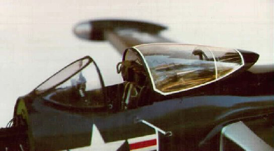
Now I found that the canopy supplied was unusable. I carved a basswood form and vacuformed a new one. I then cut out the frames from this canopy and re-glued them on the form and then vacuformed over this. Now I had a canopy with raised frameworks. After studying photos of many Panther canopies, I noticed that there is an antenna molded into the rear section of the canopy. I formed another canopy and cut the rear portion off. Using a scriber, I scribed the antenna lines into this piece and then glued it into the inside rear of the canopy. It really looks great!
Now the forward windscreen was glued into place and faired in with putty. The main landing gear and nose gear were scratchbuilt from telescoping brass tubing. I installed the gear and landing gear doors after painting and decaling were completed.
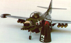
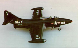
The paint is Aero Master 1044 U.S. Sea Blue acrylic flat. After the paint had dried, it was rubbed down and several coats of Flecto Verathane were applied then rubbed down with Bare Metal foil Plastic polish. The silver on the wings leading edges and drop tanks is SNJ. The stars and bars are from Superscale International and the remainder of the markings for this VF 111 bird were made by hand. Now for the really best part. If the nosecone part is done correctly, the dark blue color almost makes the joint line of the nosecone invisible. I took it to a club meeting and sat it on a table with the nose closed. After the members had looked at it, later we had a show and tell and I picked it up and opened the nose up to reveal the gun bay. That really got their attention! It was really a lot of fun. This project seems like a lot of work, but I really enjoyed doing it. I only wish that I had taken construction photos as I went along, but I never thought I would write this article either!
© Howard Weaver
This article was published on Wednesday, July 20 2011; Last modified on Saturday, May 14 2016