
General Dynamics F-16XL
By Roy Noraas
The model is based on the Revell kit no. 4786 - F-16XL in 1/32nd scale.
Introduction
The amount of work of making this model into an acceptable representation of the F-16XL is tremendous. If I had known what I had let myself into, I probably wouldn’t started it at all, but used that valuable time on other less complicated projects. But the challenge was too big to resist. If anyone should try to do the same, if would recommend that you use a Hasegawa F-16A or C as a basis for your conversion.
The kit looks quite all right in the box. The panel lines is engraved (perhaps a bit heavy). The basis for this kit is not the ordinary Revell F-16A kit. It looks more like Hasegawa’s F-16 kit. The canopy from the regular Revell F-16 kit does not fit the F-16XL. The XL also has intake trunking and a little bit more detailed wheel wells.
When I started separating the parts from the sprue, the fatal errors of this kit showed up. I compared it to a regular F-16A, and the length was identical. Then I studied the wings. They were far too small. I taped the fuselage and wings together just to see if it looked like an F-16XL, and it did. But only if you closed one eye and kept the other half open and turned of most of the light. To be honest, it looked like a toy. (On the plus side - the decals looked all right.)
I faced myself with four options; one - throw it away, two - place it on the “never-to-be-made”-shelf, three - build it as it is, four - do the corrections. One and three were no options, so I chose alternative number two. For a year or so. But the challenge of alternative four was too tempting. So here we go.
Construction
SCALE DRAWINGS
One of the hardest parts was to find suitable drawings. It didn’t find any scale drawings in any scale, so I enlarged a simple three-view drawing from a book. Compared to pictures it looked quite accurate. But NASA’s website became my best source of pictures.
THE FUSELAGE
After I had established a drawing that was accurate enough, I started cutting the fuselage. I had to cut the upper and lower half differently, as on the actual aircraft. The upper fuselage was cut at position 98 and 187 mm measured from tail. I now had an upper fuselage consisting of three parts. I made two pieces of 1,5 mm plastic card, one of 16 mm and the other of 20,5 mm length. These were bent to the same shape as the fuselage.
The 16 mm card was glued between the middle and back part and the 20,5 mm card was glued between the front and middle part. I used 5mm square strips as re-enforcement stiffeners between the cut parts. All parts were glued together with Epoxy glue. The lower fuselage was cut at position 94 and 223 mm. The same pieces of plastic card were made for lengthening the lower fuselage.
The lengthening of the lower fuselage caused the intake to be moved backwards 20 mm. Because of this, the fuselage, behind the wheel wells, had to be deepened about 5 mm. This was also done using plastic card. I used Milliput Superfine to blend in the new plastic card parts. I then rescribed all the panel lines on the fuselage. The cockpit tub was added at a later stage.
THE WINGS
The original wings were far too small. I made three attempts until I got an acceptable result. On my first attempt I separated the original wings into several pieces and glued them on to a 0,13 mm plastic card, which had the correct shape. I then filled the missing parts with auto filler. The result was a “rocking chair”. As they dried up, they got heavily warped.
On my second attempt I laminated several sheets of 0,5 mm cards. I then filled the stepping between the sheets to make the airfoil shape. The result was severe warping.
My third, and final attempt was done using 10mm (!!!) plastic card. This was a special kind of plastic, called foam styrene. It was relatively easy to work with, but the surface was full a tiny holes, which I filled using several layers of auto primer and sanded smooth with wet & dry paper. The wings were cut to outline shape using an electric jigsaw (!!!) I did the main airfoil shape using a big Olfa hobby knife. The rest was done using a Minicraft miniature sander. Several hours of dusty work, I can assure you.
After the panel lines was scribed in; the wings were glued to the fuselage using epoxy glue. The reason for using this, and not super glue, is that I find epoxy glue more flexible. The wings were faired into the fuselage using Milliput Superfine (I really love that stuff). The wing gondolas and wing fences were scratchbuilt from plastic card and added to the wings.
A new and correct gun port was added, with a little lump of Milliput above the hole. The gun gas exhaust outlet was also engraved at this stage. On the underside of the fuselage the outlet in front of the port wheel well was added. The parachute housing came from Plastic World, Belgium. The rest of the fin is the kit part.
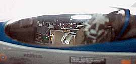
THE COCKPIT
As you probably have noticed, the cockpit hasn’t been added yet. I waited with this to avoid all the sanding dust getting into the delicate parts of the cockpit. But as a consequence of adding the bathtub at this stage, I had to temporarily remove the cockpit sidewalls of the fuselage to get it in. This was done with a razor saw. The removed parts were glued back in place as soon as the bathtub was fitted. The radome was also fitted at this stage.I used Verlinden’s book as a guide of how to detail the cockpit interior. I used the instrument panel and the bathtub with side panels from the kit. The side panels were too short so these were made to the correct length. The back wall was scratchbuilt with correct details as was the internal hinge mechanism. Some wiring and oxygen hose was added. The seat with seat belts came from Reheat. (The kit part represented the Stencel SIIS). The cockpit hood was glued in place as soon as the cockpit was detailed. This was done due to bad fit and to be able to engrave the outside hinges of the cockpit hood.
THE WHEELWELLS
The main gear was moved about 3 mm further out. I initially used it as it was, but the result was a strange tail sitting appearance of the model. The lower part of the front wheel leg was scratchbuilt from brass with reinforcement of steel pins. The reason for this was too weak to carry the weight of the model. The original rubber tires were used. Some details were added to the main wheel wells.Final Details
Now was the time to add all the small details as lights, blade aerials, static dischargers etc. etc. The nose probe was made used a brass rod and a needle. The small fins on the probe were made from stretched sprue and plastic card.
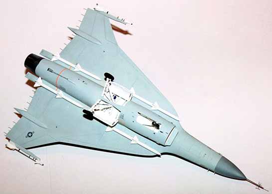
Missiles
I used the Sidewinders from Revell’s F-15 kit, and the Sparrows from Revell’s F-4F kit. The Sparrows were about 10 mm too long (!) and were consequently shortened. The missiles were added after the model was painted.
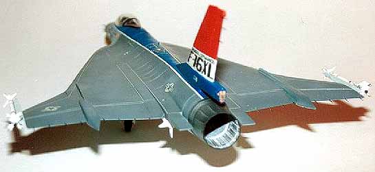
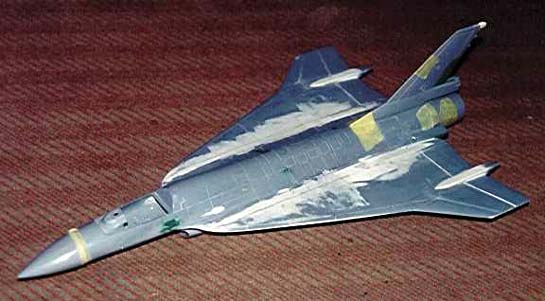
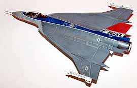
Painting and Decals
I wanted to paint my model in the original F-16XL scheme. This was also the only available option on the decal sheet. Apart from the blue spine and three-colored tail fin, the aircraft is painted in standard F-16 camouflage scheme. All colours came from the XtraColor range. The stencil data and walkway came from Superscale F-16 decal sheets. Total length of walkway on the model is about 1,5 m (!!!!).
Conclusion
An attractive model when finished. I don’t know how many hours I’ve spent on this model, but the number is three-figured. For those of you who would like to try this conversion, I recommend that you do it using the Hasegawa kit. But be prepared for a lot of work.
References
- NASA's Webpages:
http://www.dfrc.nasa.gov/EAO/FactSheets/F_16XLFACTS.php
http://www.dfrc.nasa.gov/gallery/photo/F-16XL1/index.php - Verlinden Lock On No.1: F-16
- World Airpower Journal:
Volume 5, 21,22 - Bill Yenne
- The Great Warplanes of the 1980s
Bison Books 1986, Michael J.H. Taylor - Jet Warplanes - The Twenty-First Century
Bison Books 1986, Christopher Grant - Top Gun - The Ultimate Airborne Action
Quintet Publications Ltd. 1992 - Aerospace Publishing:
The World’s Great Interceptor Aircraft - 1990 - Aviation Fact File:
Modern Fighting Aircraft F-16, Salamander Books, 1983
© Roy Noraas
This article was published on Wednesday, July 20 2011; Last modified on Saturday, May 14 2016