
Tamiya 1/32 Vought F4U-1A Corsair: Goodyear Aircraft Production #4 - Part 1
By Rodney Williams

Part One
I started building plastic model airplanes during the late 1970s for clients and for myself.
With over 375 built models as of May, 2016 this Tamiya kit is the first model that is at least 97% perfect when it comes to quality of molded parts, including how well they fit together.
The instructions have “diagram-type” drawings and they are produced in a “semi-booklet” form, including an extra folder of color images of a real Corsair.
I’m no stranger when it comes to the Goodyear Aircraft Corporation, (G.A.C.) Corsairs as I lived in Akron, Ohio/USA where G.A.C. made over 4,000 fighters during WWII including the F2G version.
As a young kid I went to the factory on weekends with my father who worked there and became one of many kids who were called Delivery Boys.
This model will be my 27th Corsair so I wanted to build something different than a racer and/or a WWII fighter as was depicted on the kits box-art.

I found a photo of a FG-1A No. 4 parked at the 1946 Cleveland, Ohio/U.S.A. National Air Races which had a yellow cowling with a large black “4” on its cowling. Great news as this photo would be put into my collection as I went to all the air races from 1946-1949 with my parents.
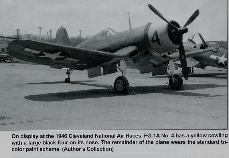
I have worked with Jim Sullivan who is well known and has produced Corsair Books for Squadron Signal Publications, so I contacted him in reference to his collection of Corsair photos. I emailed my data to him concerning “No. 4”. Jim had an excellent image of it and sent it to me.
The Building Begins
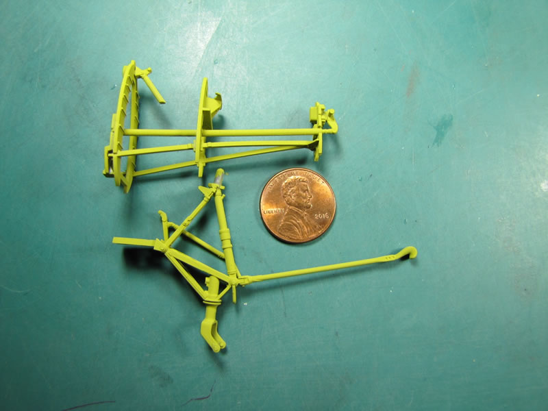
I start looking at all the parts that are connected to the many trees and then begin to remove dozens of them and put them into marked foam trays (cockpit, tail wheel, wing, etc.).
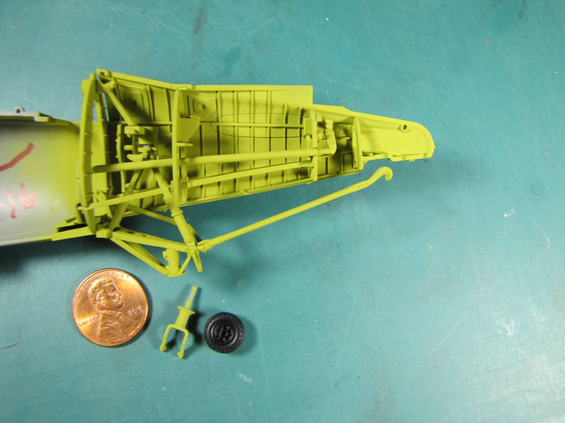
The builder has the option to start with any of the building procedures so I choose to work on the cockpit, then move onto the tail wheel area.
All of the cockpit and tail wheel parts fit together next to perfection and are dry fit into their areas within the fuselage.

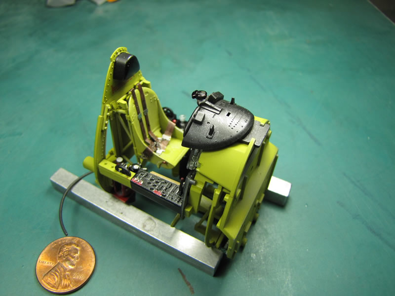

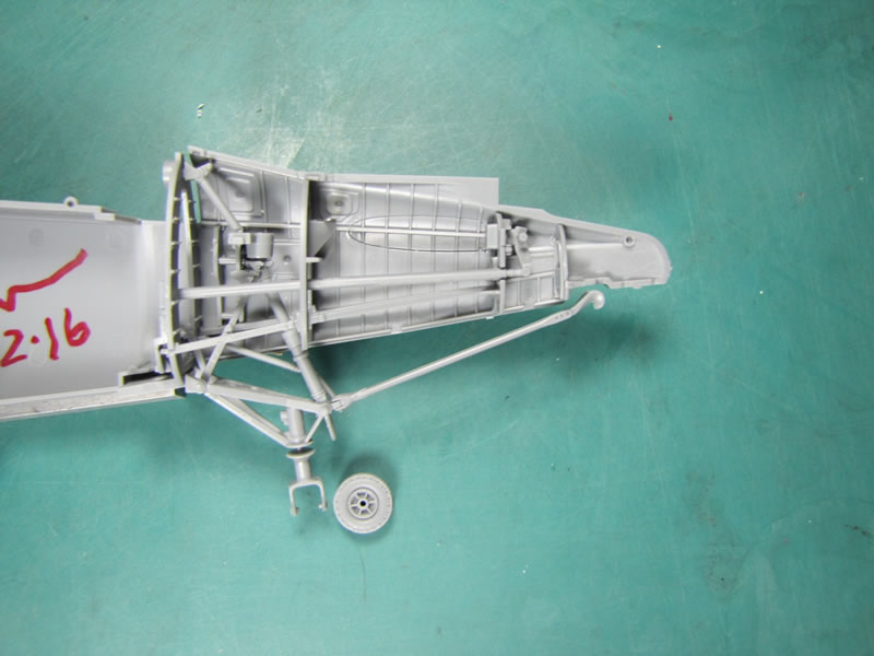

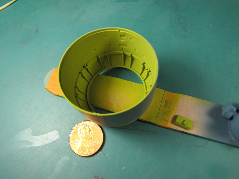
I have used Tamiya acrylic paint since it came on the market many years ago so I used their paint, which comes real close to matching my pieces of painted aluminum, which I took home in 1944/45 from G.A.C.
The name is written on one of the parts that I have and is named: LEMON–GREEN/A-1-A 2024.

The “TEMP 3” that is marked on the part must be a part number.
One photo shows my bottle of SnJ model products Spray Metal polishing powder that I have used since 1985. I gently rub it onto my painted parts and wipe some of it off which simulates paint flaking etc.
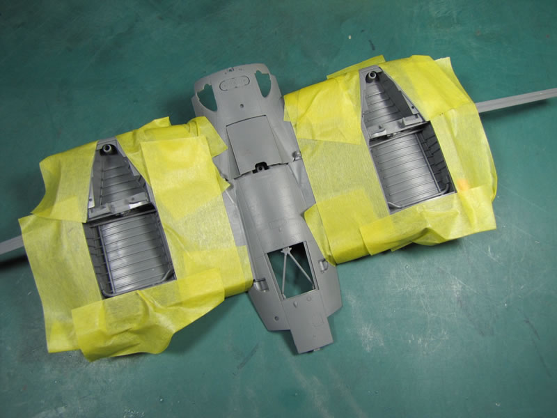
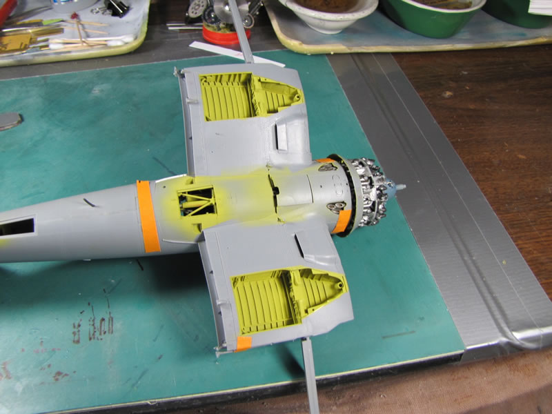
After reading the engine’s assembly instructions I choose to revise some of the parts. I added some ignition wires to the pre-painted engine cylinders and glued the cowling parts together. This method gave me one complete cowling that just slipped over the installed engine.

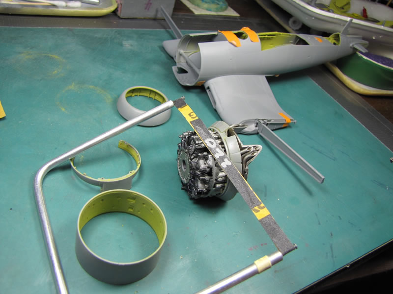
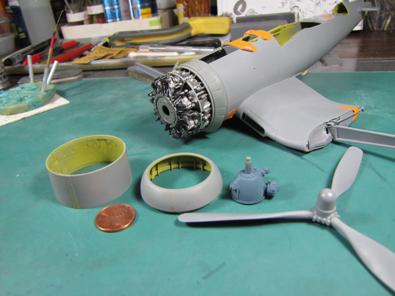
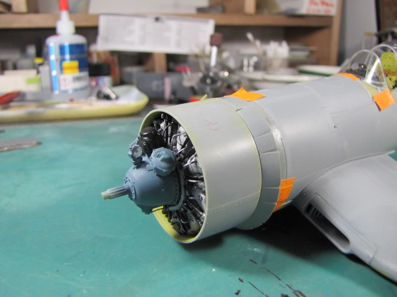
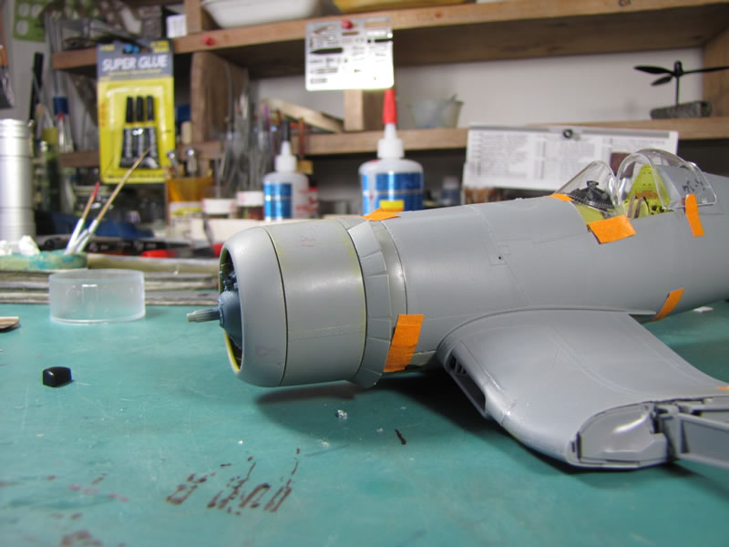
However this method of assembly created a minor problem as my cowling would not slide over the engine. I had to sand down the outside of the engine cylinders slightly with some home made #220 grit dry sandpaper.
In reality there are a few inches of space between the engine and the cowling which is attached to the engine/cowling mounting rings.
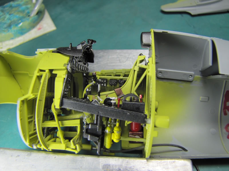
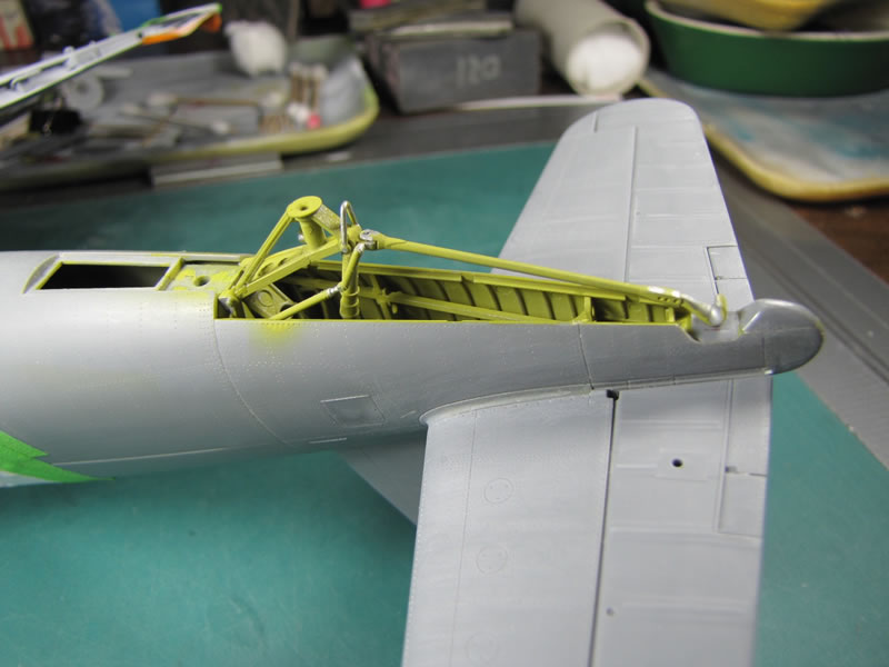
The fuselage halves were dry fit together and since they mated up next to perfection I just super-glued the two together.
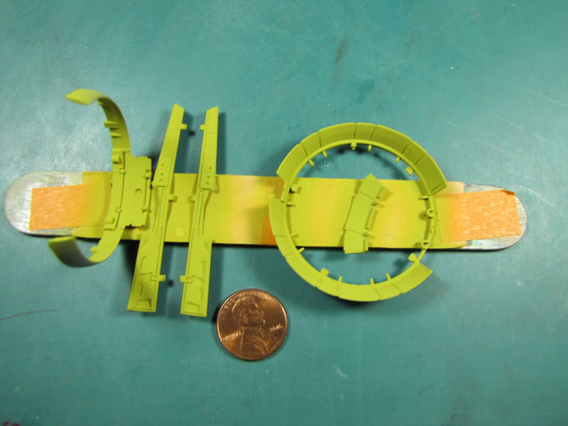
There are lots of parts that make up the complete wing so take your time building it. My entire wing went together just like the fuselage parts then I painted the interior sections.
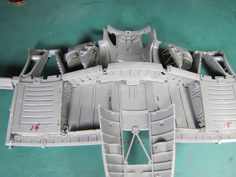
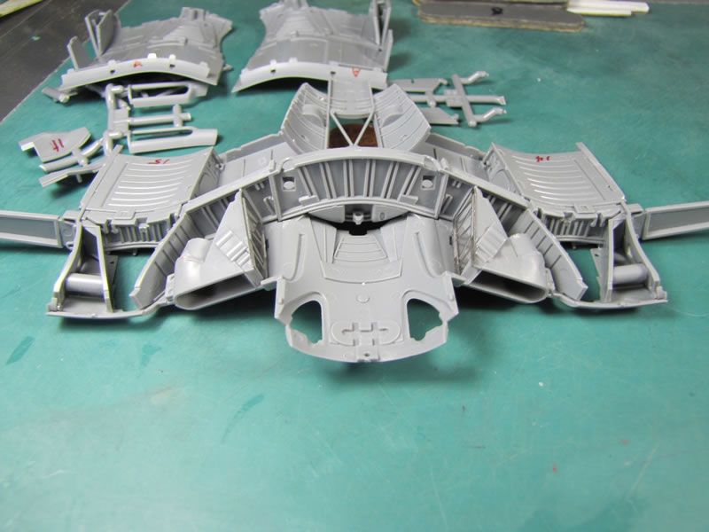
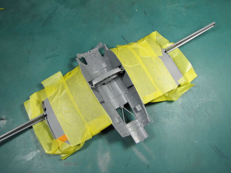
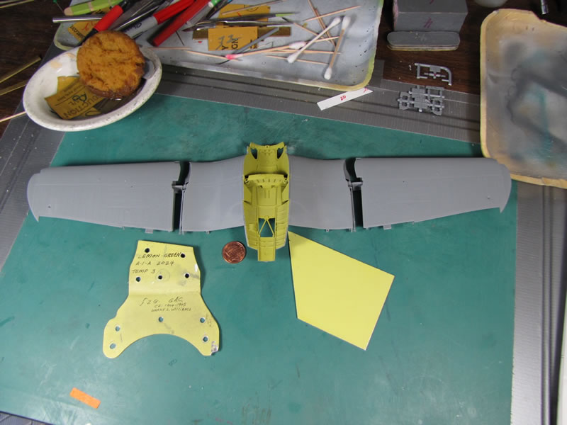
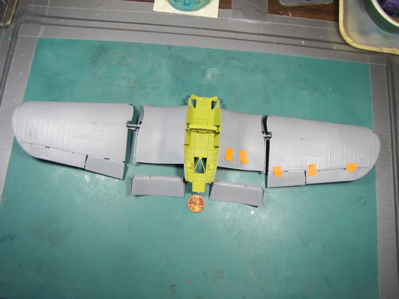
I dry fit the center wing section to the fuselage and checked it for proper alignment then glued it to the fuselage. The outer wing panels were finished in the same manner and would be glued on at a later date.
© Rodney Williams 2017
This article was published on Thursday, March 02 2017; Last modified on Tuesday, March 14 2017