
Dragon 1/32 Early Production P-51D
By Jay Wheaton
For this modeling effort I obtained a nearly full set of microfilmed prints of NAA (North American Aviation) drawings of the P-51 series in DVD format (available from several places on the web). This is a rare luxury - not many aircraft of this vintage have manufacturer´s drawings available. I also obtained the 4-sheet set of drawings by Mr. Charlie Neely which are probably the state of the art profile pictures of the P-51D/K (he also has the P-51B/C), in 1/16 scale. There are lots of publications out there on the P-51 which are helpful, but the drawings reveal everywhere the errors and omissions present in the kits available today, and can commit the serious modeler to a world of endless scratch building sub-projects in an attempt to get that "nth degree" accuracy desired.
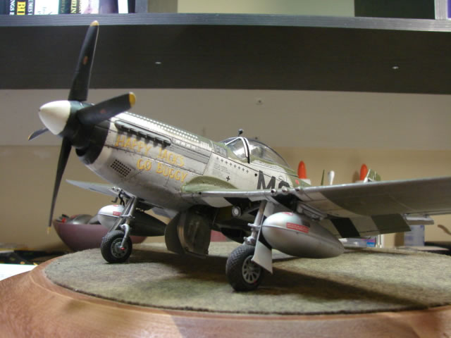
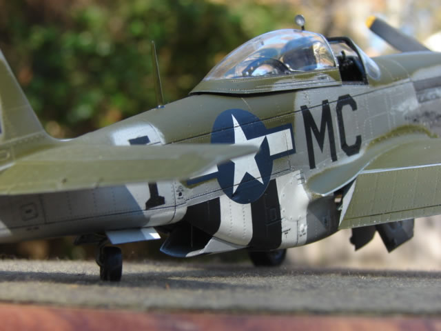
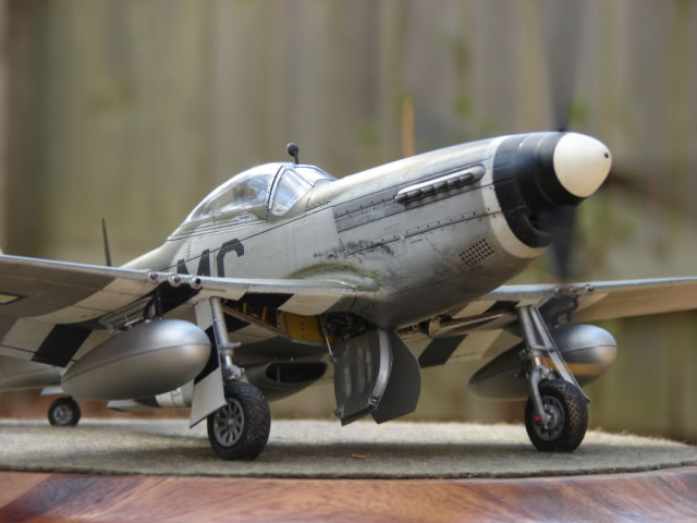
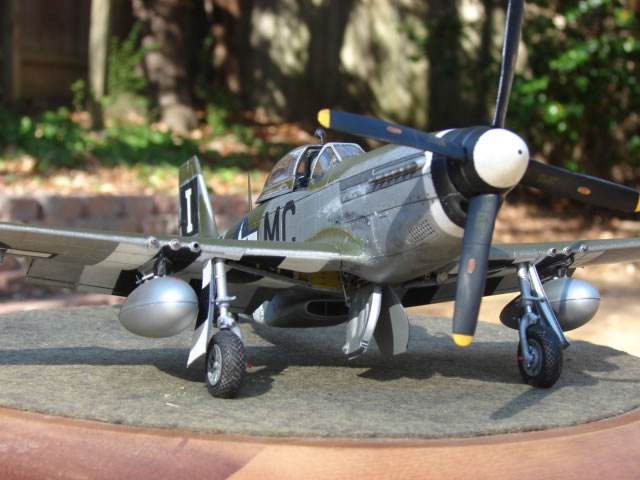
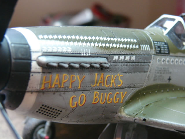
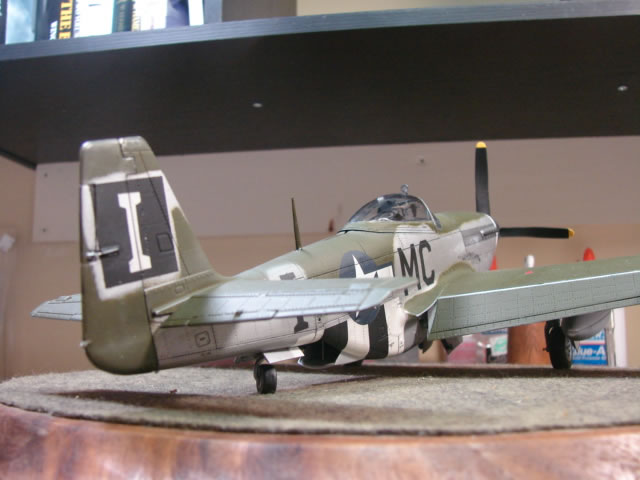
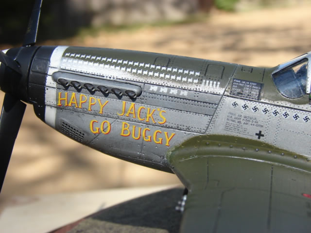
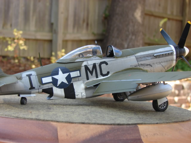
The subject is Happy Jack´s Go Buggy, P-51D-5-NA A/C serial number 44-13761, piloted by Jack Ilfrey of the 20th FG, 79th FS, 1944-1945, Kingscliffe England. I wanted to build an early D-model without the fin strake and this aircraft is one such animal. A stroke of luck got me the Cutting Edge "Big Stud Ponies Part 2" decal set which is out of production - otherwise this would have been Lou IV, another early D and another lucky find from a dusty decal drawer at my local hobby shop. Although an early D, the Go Buggy completed a heckuva lot of missions and apparently lasted until the end of hostilities at least. It replaced a commonly modeled P-38 of the same name - the 20th FG being well known as a P-38 group before transitioning to the P-51 in mid-44. Ilfrey´s Mustang also sported two different paint schemes during its service (the earlier simple black/white cowl stripes and the later "piano key" style), and two different squadron letters ("O" and "I"), and for a period of time had invasion stripes. I opted for MC-I with earlier cowl stripes, and invasion stripes. Today´s fine flying example is painted the same way.
The Dragon model has much written about it which I won´t repeat - let´s say it has its strengths and many weaknesses and needs much work. I can live with all but the mildly misshapen lower engine cowl and carb intake area which I just don´t know how to fix other than some filing. I appreciate the offering of the "early production" version although I have found that early production D-models had much more different than merely the lack of a fin strake which is evidently all Dragon changed from their original late D-model release. D-models evolved continuously during the war.
Every effort was made to represent accuracy for this particular model and serial number - careful inspection of the engineering drawings and the effectiveness of the different configurations usually showed what is required. Also, the on-line P-51 SIG folks were immensely helpful providing great photos and explanations and other data - I cannot thank them enough. Jerry Rutman´s kits were also very good additions, especially his extensive cockpit set which includes a detailed fuselage tank bay. Fit was actually pretty good. By far, the most difficult modeling issue in reproducing accuracy is thick plastic gauge. It is amazing how .04 to .05 inch think plastic on a 1/32 scale model (which scales up to 1.5 inches thick!) gets in the way of things that in real life were tucked inside of .03 to .06 inch metal skins that scale down to .001 or .002 inch. And believe me - the P-51 is literally packed with stuff from stem to stern. My computer drafting package helped immensely with this - draft up rough 3D solids of the parts you want to fabricate, shown installed in a wing or fuselage with overly thick gauges, and revise geometry as necessary. Let´s get started:
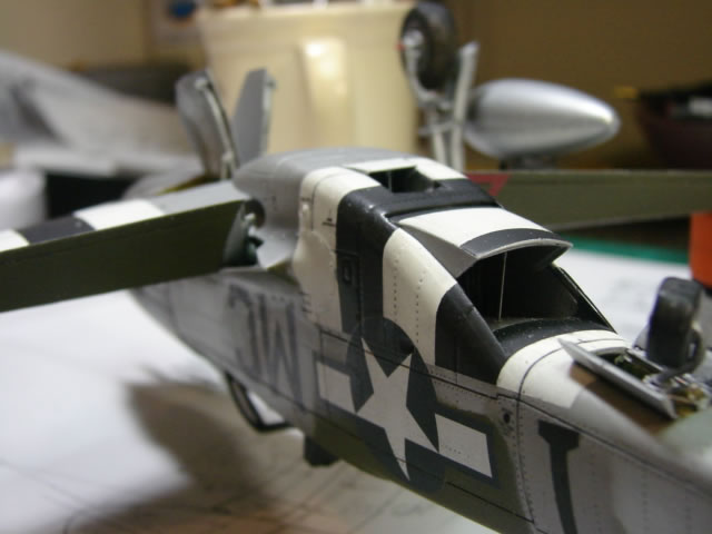
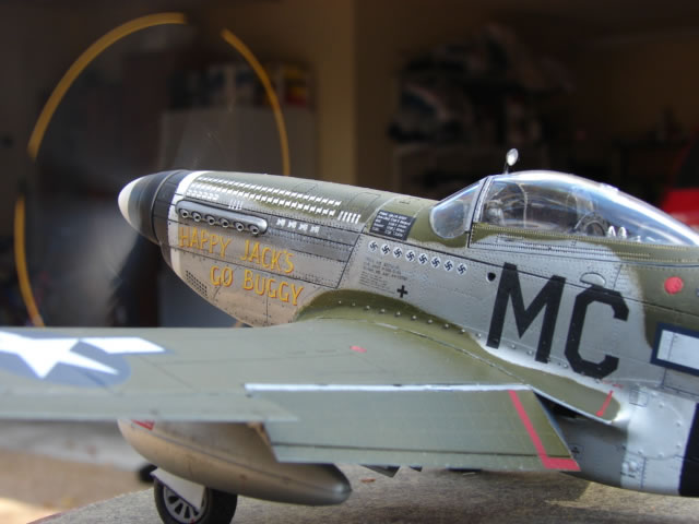
The Nose
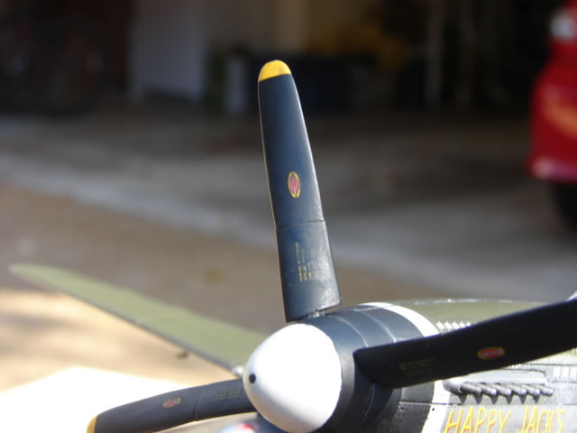
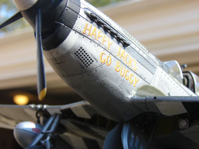
The bullet fairing is from Rutman, with modified larger holes for larger and more accurate blade roots. The resin prop blades are from Quick Boost and to my eye look to be more accurate than anything else available. The Rutman blades are pretty good too, and with some whittling can be made right on. The Dragon prop blades are incredibly inaccurate and the Hasegawa parts look a little thin. All of them have spindly blade roots that need to be thickened. This time around I subdued the stenciling on the blades - more like what is seen in war photos.
Note the carb air intake grills (perforated) - this came from an Eduard PE kit and is a great improvement over the inaccurate renderings on the Dragon fuselage. But the modeler must take care to make good openings to accept the PE parts, and a good compound curve must be shaped into them.
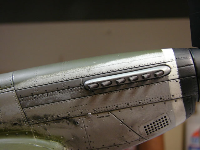
The engine exhaust stacks and the fairings are badly modeled regardless of manufacturer, and I professed to do better. These objects consumed an amazing amount of time and effort. My previous P-51´s all have the Moskit shroudless exhaust stacks which are somewhat easier to deal with. The complex shaped fairings are carved out of 1/8 inch thick plastic stock to dimensions defined in a fabulous NAA drawing of same, and some computer modeling. The cowling cutouts were widened to spec and local gauge thinned drastically to accept the fairings. The stacks themselves are 1/16 copper tube with reamed ID and a ring of paint on the ends to accurately simulate doubled up welded steel gage. Folks, these exhaust details are "nth degree accurate" and suffice it to say it was a long multi-step tedious process - please email me if you want details.
Cowling lines were correctly rescribed on the underside of the engine cowlings, which necessarily took place after the wing was attached to the fuselage. Only then can the ugly wing/fuselage joint be puttied over and fixed. This is an area of the P-51 that saw many variations over time BTW.
Cockpit and Canopy
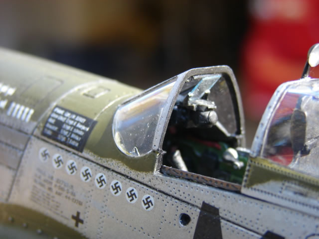
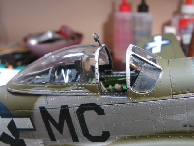
The fit of the Dragon wind shield is a problem not easily remedied. I got lots of advise on line and proceeded to whittle away with all the limited skill I have, with a result I am not totally happy with but it´s gotta do. I did add some plastic sheet on the inside of the forward frame to simulate the thick bullet-proof front glass. The Rutman N9 gunsight is terrific - the .010 thick clear plastic is my own making.
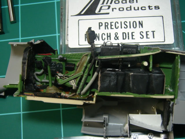
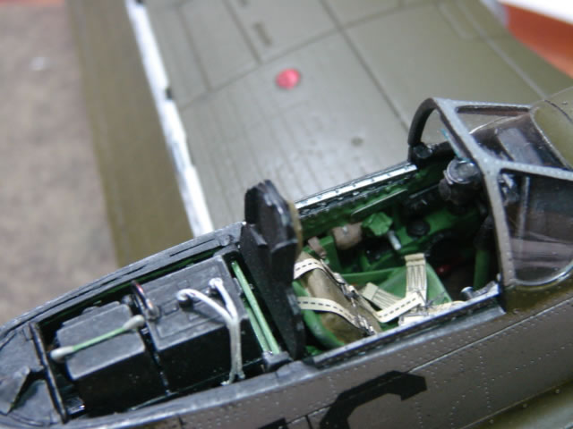
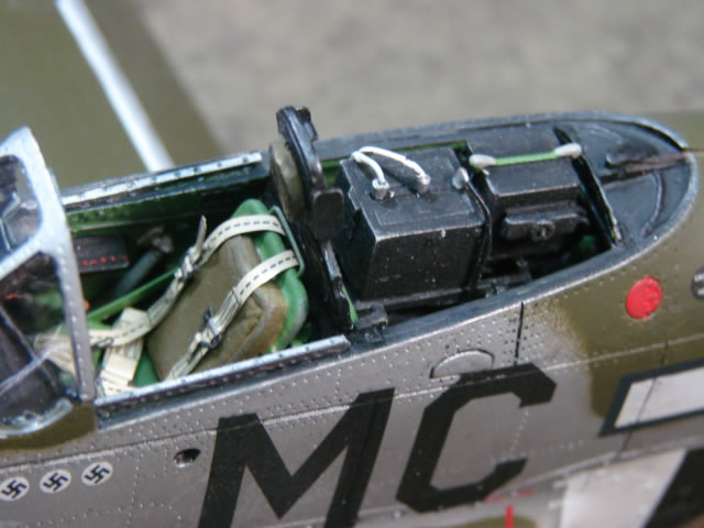
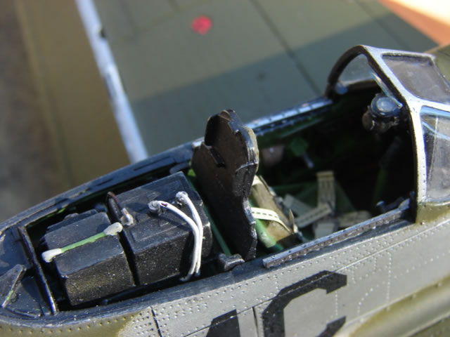
Rutman´s early D-model cockpit is very elaborate and a lot of fun. It is a huge improvement over the Dragon offering. Way to go Jerry. I used most of it as is with little modification - mostly just a new scratch built radio rack above the excellently portrayed fuselage tank.
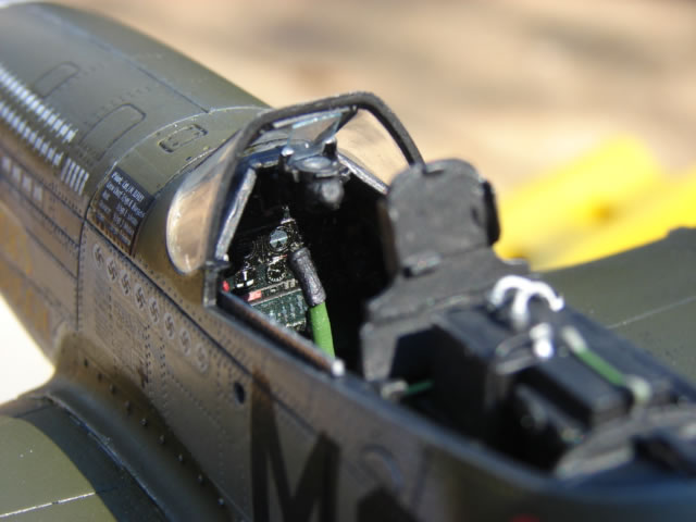
The canopy and canopy rails were an effort. I used the Dragon canopy and added in a rear deck and plastic stock thickness along the side framing, and approximated roller bogies which fit over the tracks. The tracks are a combination of Eduard PE and stock plastic, carefully oriented to match the rollers bogies on the canopy. Note the tracks run parallel with one another - when you think about it, they have to. This is usually not correctly modeled.
The canopy sides, under the thickened framing were thinned down to the minimum I could risk in efforts to allow the canopy to sit right when slid back. The aft end of the canopy should almost rest on the fuselage in that position and this is not possible with the as-is Dragon canopy (nor the Hasegawa). On real life Mustangs, the bottom skin of the canopy, which is only about 0.05 inch thick, actually overlaps the fuselage by about � inch even when closed - something that cannot realistically be modeled at this scale.
The curved canopy beam was designed on the computer and made from thin plastic sheet as closely to the drawings as possible yet made to clear the radio and battery as the canopy slides back, something the Dragon, Hasegawa nor Rutman beams do not do. The landing light out of the Hasegawa kit was used to make the exterior rear view mirror that adorned Ilfrey´s aircraft.
Deep underneath the coaming in the shadows is an unbelievable Big Ed instrument panel. But it´s so hard to see. As is the excellent Rutman fuselage tank under the radio rack.
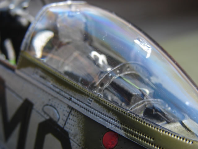
Finally note the clear cover and interior bracket I put over the wire antenna slotted hole I put on the top of the canopy bubble. This antenna and its Detrola radio were not used in the field, I am told by many reliable sources. So Mustangers - do yourselves a favor and don´t bother putting a wire antenna on a P-51 model. Make an opening in the canopy and put a clear cover over it.
Aft fuselage and empennage
The P-51 had an amazing interior air ducting from the centerline air scoop under the wing to the oil cooling radiator and engine radiator. No model manufacturer has done anything with it, nor did I. But I did redo the exit doors which are poorly done by Dragon. The oil cooler exit door was completely fabricated from sheet stock and has a little off-center actuator rod hiding in the slot. The larger radiator exit door has a properly curved inner surface insert and an on-center actuator rod of its own. Lastly I added a thin piece of sheet stock in the inlet scoop to depict the centerline support strap meant to stabilize the opening.
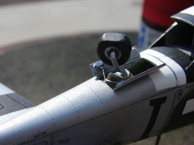
The tail gear bay is pure Rutman - his part shows the canvas boot that covers all the clap-trap in there. Many modern day renovated Mustangs do not have this item, but wartime aircraft did. The Dragon gear doors and cutout are too short by something like .10 inch. I increased the cutout, and scratch built the gear doors, with tiny actuating rods. The strut is scratch built from 1/16 copper tube. The wheel is Rutman, but I increased the width some by cutting in two and sandwiching a piece of plastic sheet stock.
The rudder and elevators were upgraded to show tab control rods. Many are not aware that the LH and RH elevators and horizontal tails were identical and just turned upside down on the RH side. So the elevator tab control rod is on the lower surface LH side and upper surface RH side.
Let´s go to the wing
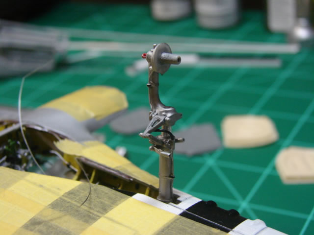
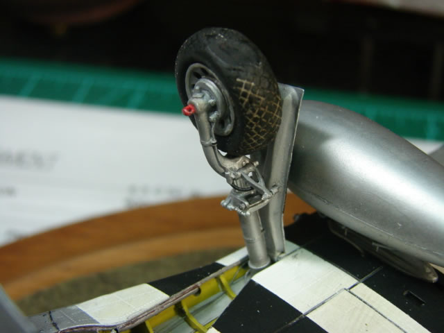
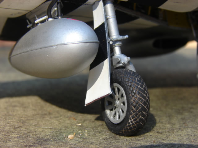
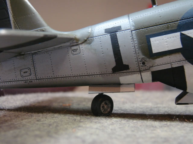
Landing gear: After much hand wringing I decided to fabricate my own LG struts. The Dragon and Hasegawa parts are not worthy. I had the Rutman LG and almost used them. The only kit parts here are the Dragon lowers which were heavily filed on and puttied to obtain a more accurate (and thinner) shape. The rest is aluminum tube and plastic sheet stock. The oleo tubes should be .100 inch diameter and there is no such gage that I know of; I used 3/32 alum tube for the shiny effect, which is just a bit too small. Some details were shear microsurgery - the red tie down rings, the torque links, the door links and the torque link lugs come to mind. The brake housings were scratched out also, as well as a sturdy support tube on top of the gear for mounting to the wing. I recommend a support tube like this - number one it´s authentic, and number two it is much more robust than just gluing the strut into a shallow hole. But then the hard part is mounting it in the wing on a trunnion and the front spar, at the right rake angle (11 deg from wing reference plane). You might notice the jig I made for gear location purposes. Please note the little wire pins and nuts on the torque link and door link joints. Hydraulic brake tubing and flex hoses are compliments of Detail master wire - I forget the gauges. The wheels and tires are Rutman, multi piece, very cool and pretty correct.
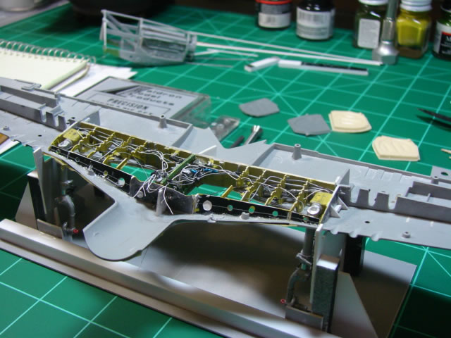
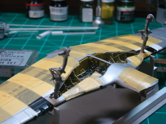
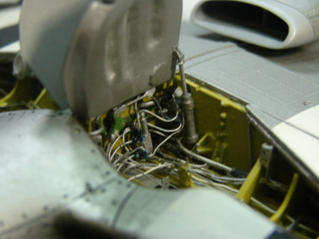
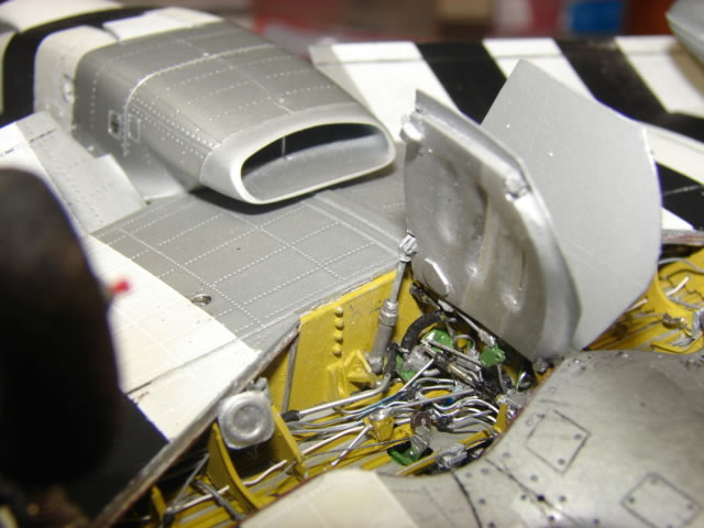
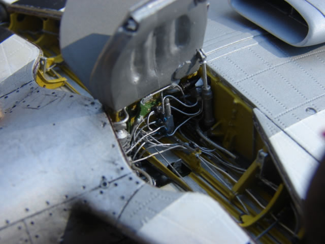
Landing gear bay: Again there was hand wringing and I made the huge decision to scratch it all out. Rutman has a good alternate LG bay kit, but I chose otherwise - a decision which doubled the length of the project, and was the dominant sub-project of the entire effort. For structure I used the Rutman front spar segment because of some complex fittings on it I could not reproduce, but scratch built all the LE ribs, the auxiliary LE spar, the upper skin stringers, and the very complex centerline rib with thin gage (.005 or .010) plastic stock. Engineering drawings were used for all parts, with designs modified to account for excessive skin gage. This was tricky when locating penetration holes for hydraulic tubing, fuel system tubing, cables, and wiring. As can be seen, every effort was made to include all systems parts - tubing, actuators, brackets, cables, fairleads, pulleys, you name it. All systems are represented right down to the bomb drop cables. The landing light and its mounting bracket were scratch built per drawing and it points in the proper direction (slightly outboard and down). It is also the proper size, the Dragon and Rutman parts are too large, and the Hasegawa part is too small.
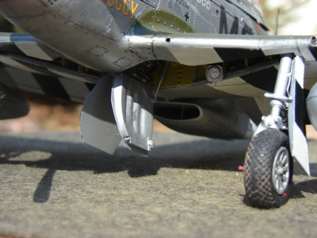
Main landing gear doors: For these parts (all four) I salvaged the inner portions of the Hasegawa parts and trimmed away the outer skins, replacing with thin plastic sheet stock trimmed to engineering drawing dimensions. This provided some needed thickness. A fellow named Geoff (aka Ironwing) on LSP turned me on to this, and it worked out really well. To be sure, I modified the shapes of the inner parts as best I could, and included details like latches and hinge lugs, etc.
Machine guns: The guns were scratch built using several sizes of aluminum, brass and plastic tubing. The toughest part was the spherical shaped housings the barrels rest in, which are clearly visible. Each gun looks a bit different from the other with the inboard guns buried inside blast tubes, and the others with varying amount of protrusion from the wing LE, all according to the gun installation drawing from NAA. The holes in the wing were carefully enlarged to accept these parts. The result is highly accurate, as good as I will ever be able to do.
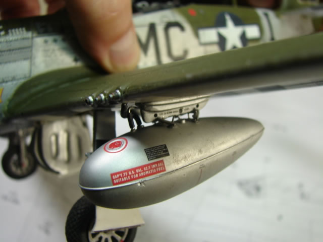
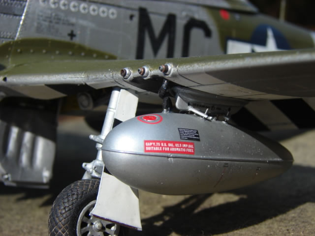
Bomb racks and 75 gallon droppable tanks: NAA went through several versions of bomb racks on the P-51 series, and even the D-model saw changes. No one has very good P-51D bomb racks. The best I could do was thin down the Dragon parts, rather than thicken the Hasegawa parts. Holes were added for sway brace clamp bolt access, and a viewing window, and then scratch built sway braces were made, (sort of) per drawing. Finding the right drawings was a chore, as early version sway braces which looked quite different were replaced in production and also in the field with more modern parts. I think I have the right ones for the Go Buggy. I was going to use the big 108 gallon non-metal tanks which are commonly seen on 20th FG Mustangs, but the Dragon and Hasegawa parts are not accurate for various reasons, and apparently a good aftermarket tank is no longer available. So I resorted to the trusty 75 gallon metal tanks which are more accurate.
Tip lights and ID lights were done using Waldron punch dies and whittling. The Dragon tip lights are little slivers of clear plastic which barely survive being trimmed from the sprue. Note the wing tip fairing has a depression to accept the tip lights, as defined by the tip fairing drawing.
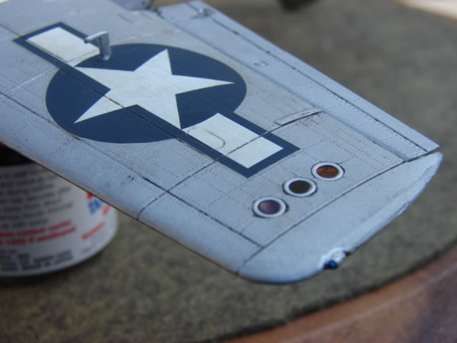
Painting and decals - Tamiya bare metal silver and/or gloss aluminum were used for everything, and then dark green Testor´s added for the camouflage. Zinc chromate green primer was used inside the cockpit under the sills and black above the sills. Yellow zinc chromate primer was used in the wheel wells, along with some silver and green depending on the detail. I had some problems with some but not all Tamiya spray paint shriveling up after applying dull coat (a horrible thing to happen - I stripped the lower wing halves and painted them over because of this), so I used Testor´s black and white for stripes. One of these days I will graduate to airbrushing - not yet. The "I" buzz letter was painted on, and on the fuselage it went over a locally sprayed gray primer or the like, as was done actually by the boys in Kingscliffe. Gloss clear was applied for decaling, then a final dull coat, and some weathering wash with black and brown water color paint. Most of the small decals one normally sees on P-51D´s are black lettering which is lost on a dark camouflage top coat. In the field some markings were replaced with white or yellow if covered by dark paint, some not. Either way - white of yellow decals were not available, or at least I am not aware of where to get them, so some markings are absent.
This model was a joy and to make, yet the undertaking was so daunting and taxing that I hesitate to repeat it. Having the NAA drawing set is a good and a bad thing - good for unsurpassed accuracy, and bad for turning a reasonable project into a marathon. I would like to thank Eric for filling in some important gaps in my drawing collection, by the way. And also thanks once again all the helpful folks at the P-51 SIG for too many answers to list. Hope you enjoy it.
Starting up and flying off
© Jay Wheaton
This article was published on Wednesday, July 20 2011; Last modified on Saturday, May 14 2016