
Elite Forces 1/18 F6F Hellcat Part 9 - The Fuselage
By Rodney Williams
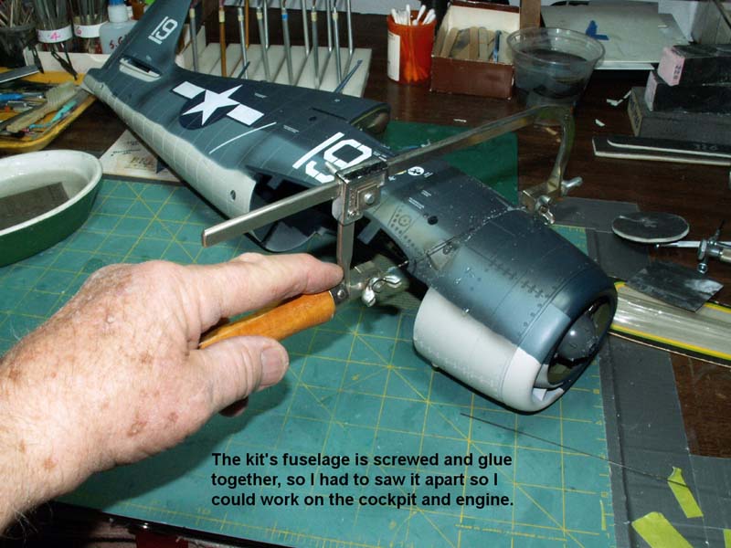
In order to work on the cockpit and engine I had to cut the fuselage apart as it was put together with some screws and then the company put lots of glue on several other parts.
Since the center wing section was not attached to the fuselage I could look up inside the model which gave me a good idea as to "how and where to cut".
I started this project by removing the antenna wire which was made out of some type of string. The canopy was what I call a "slider" which could be moved to it´s open and/or closed position. It just popped it off of the model real easy. The windscreen was another story and was glued to the fuselage on both sides and at the very front. I lucked out and was able to cut it loose without damaging it.
Secondly, I dug out the glued-in plastic screw caps and unscrewed the screws. However, some of the screws broke off and I had to reach up inside with my long rough-cut saw and saw the telescoping retainer tubes apart.
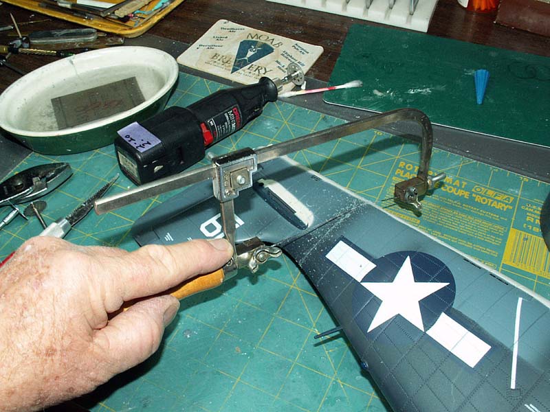
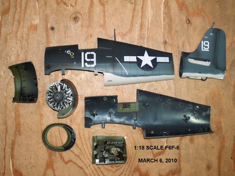
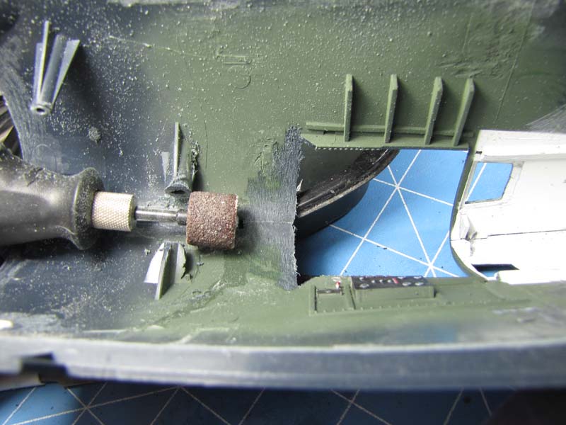
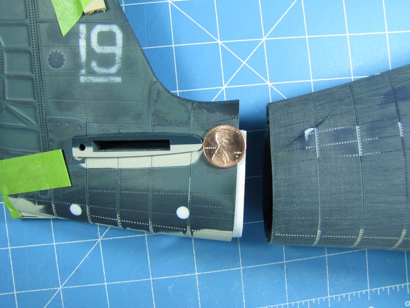
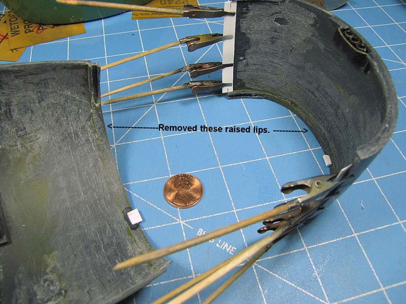
I sawed off the cowling and then did the same thing to the tail plane at one of the kit´s vertical panel lines. With all the tubes cut off I was able to pry the two fuselages halves apart with a little cutting here and there.
The cockpit was glued to the right half of the fuselage so with a bit of cutting it came out in one undamaged piece.
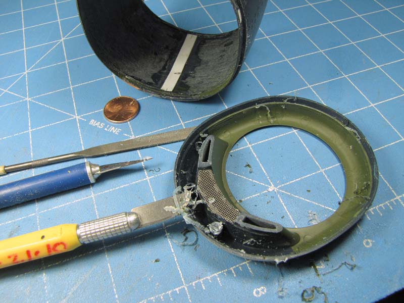
I took extra care in separating the cowling´s "speed ring" and then I removed the engine which had only one bank of cylinders.
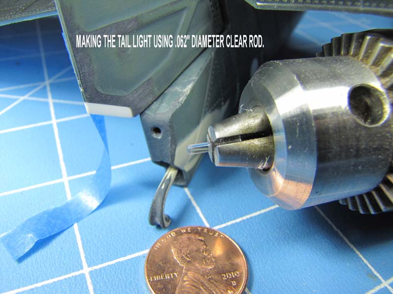
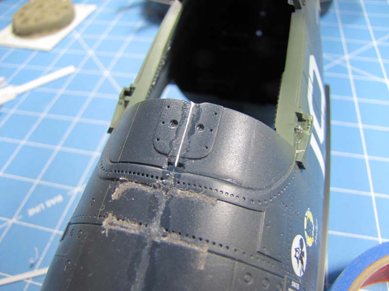
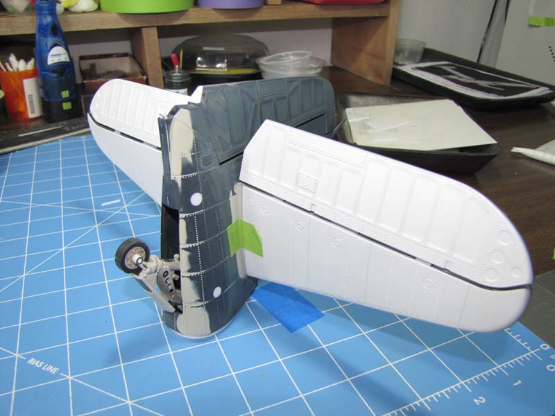
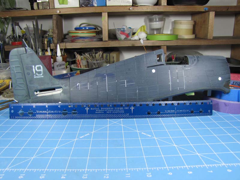
A close-up photos shows that I added some white styrene flat stock to the bottom of the rudder, then I fashioned the tail´s clear navigation light. This light was made just like I made the gun camera lens, which I explained in a previous story. I filled the top of the instrument panel cover with some thin flat styrene stock.
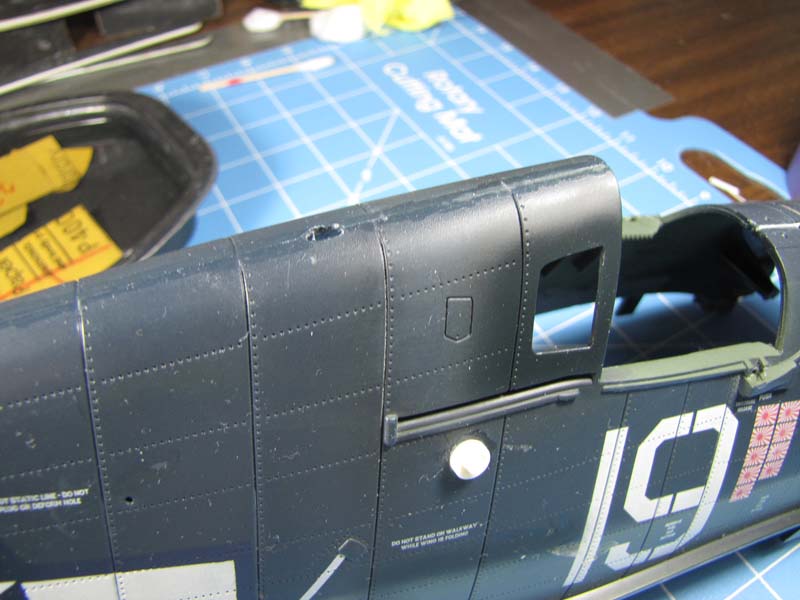
You will "note" that one photo shows the finished side windows behind the cockpit opening. I´ll go into more detail about "how" I accomplished this in my "COCKPIT" story.
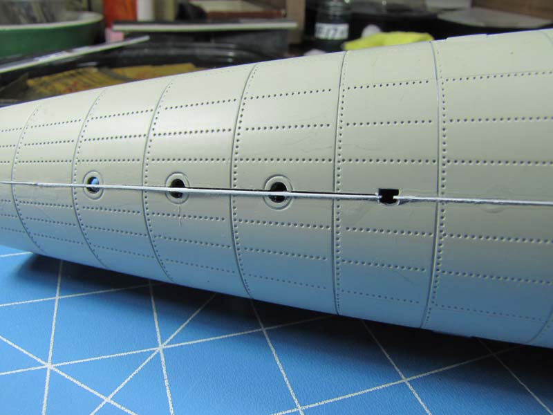
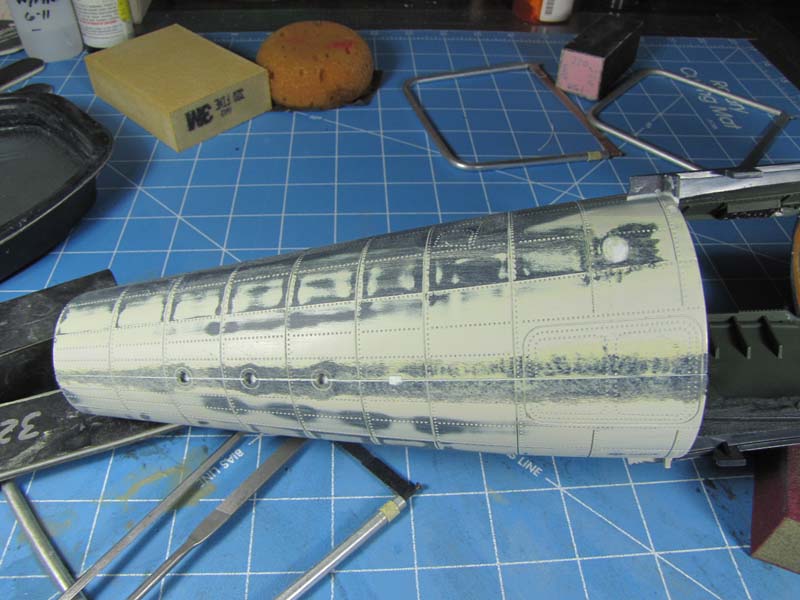
I removed the 3 colored recognition lights that were on the bottom of the fuselage, including the small antenna and glued the two fuselage halves back together. I filled in some gaps with sheet styrene then rough sanded it for the time being.
The tail wheel was retractable so I put it in its down position and clean up the mold marks and drilled out the holes in the frame work.
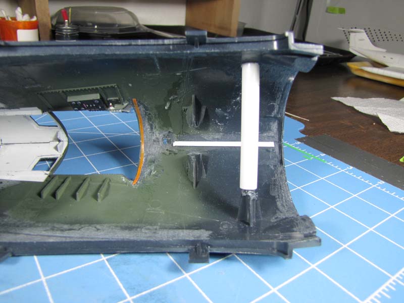
I filled in the screw holes with several sections of styrene telescoping tubing then I thinned to scale the instrument dash cover and added round tubing back into the fuselage for support. The cockpit side walls were then painted.
I put some .020" thick styrene on the inside of the front section of the tail plane, (see photo). This method lets me slip this tail section of the fuselage into the back section of the main fuselage front section. This holds the two sections together so I can "align" them up. When my "eyeball" method of alignment is in order, I just add the super glue to the seam and "presto", it's together.
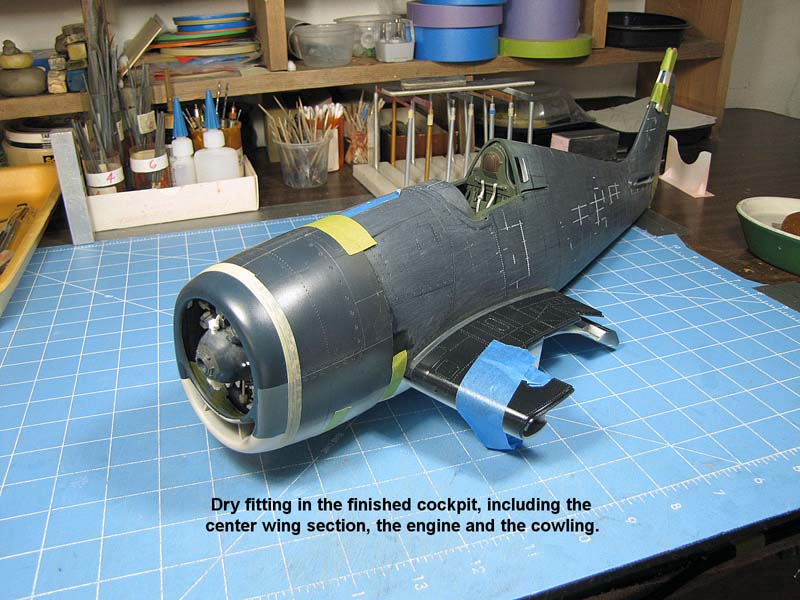
I slipped on the finished center wing section including the half finished cowling to make sure that everything is lining up A-OK!
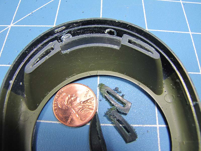
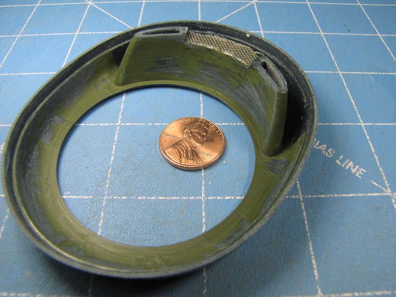
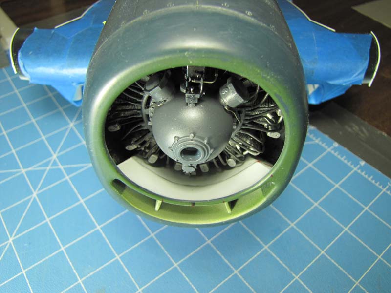
My next operation was to install the screen that can be seen on the back side of the center opening on the speed ring. Once this was accomplished I attached the ring to the cowling which had already been glued together.
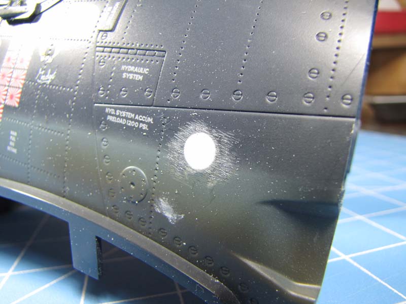
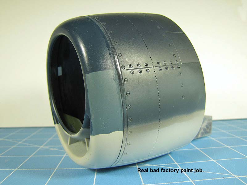
I tossed in a photo showing how funny the "tri-color" paint looks on the cowling and speed ring.
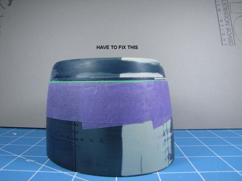
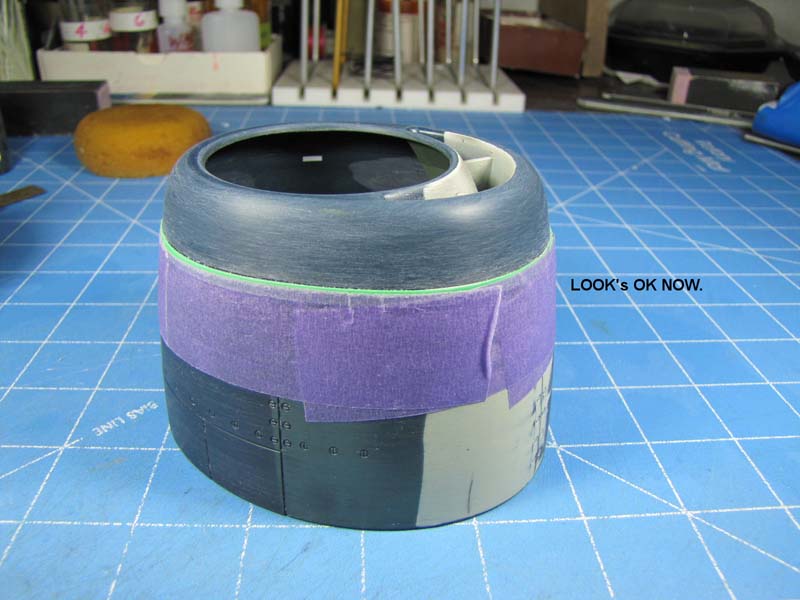
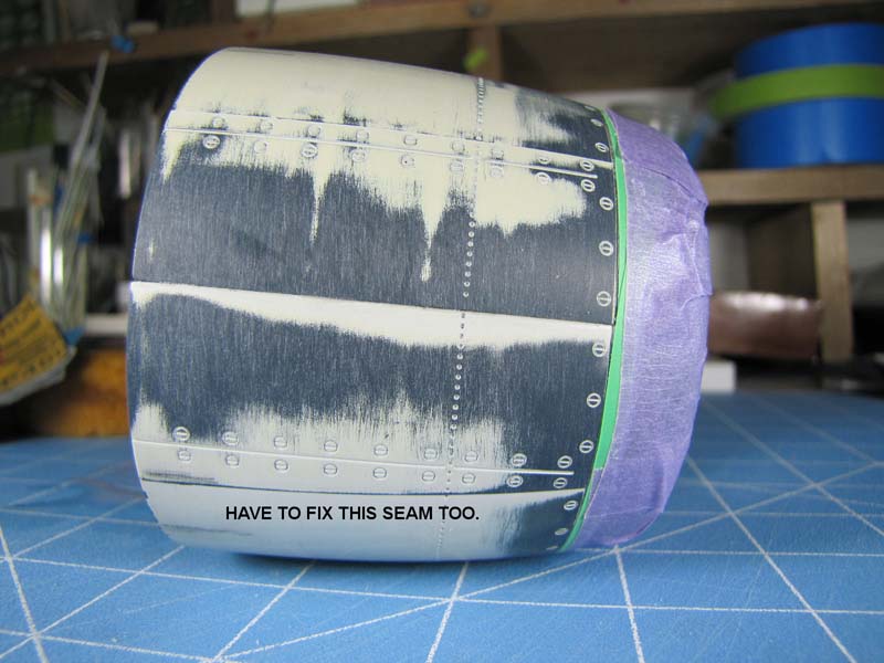
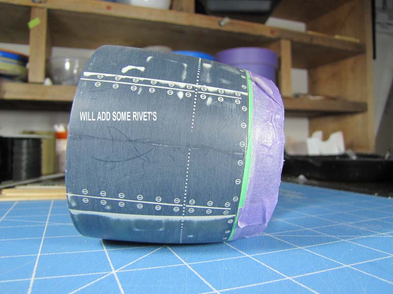
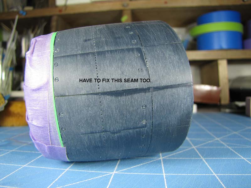
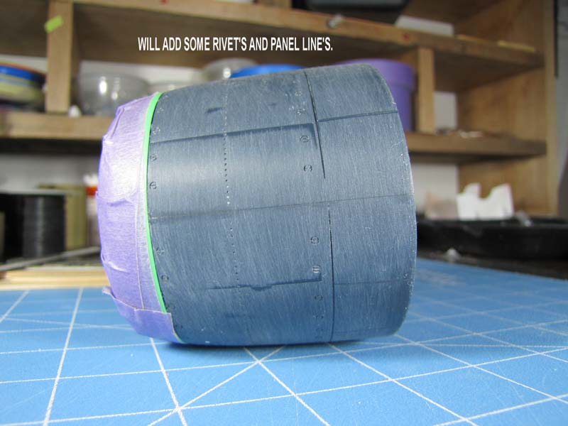
Here are six photos that show you that the cowling parts did not line up very good. To prevent sanding away some of the large looking screw heads, I applied tape on the cowling and on the speed ring. Some rivets and panel lines will be replaced later.
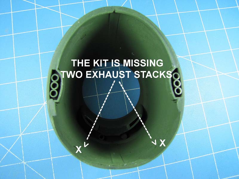
Who forgot to add the other two exhaust stacks on both sides of the cowling? I will have to fix this problem on the center wing section.
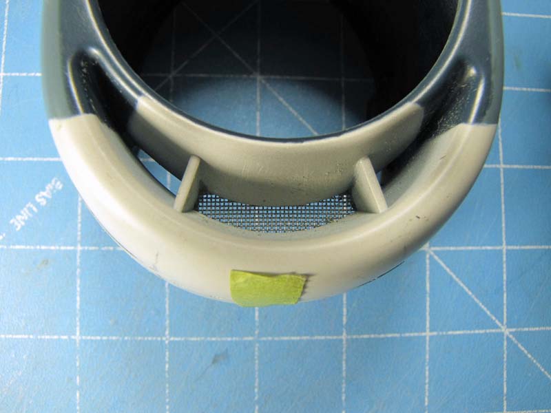
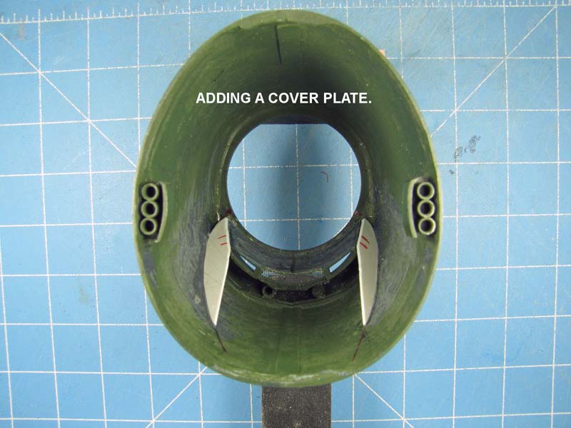
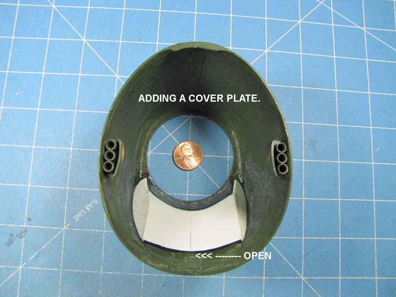
I added a cover plate on the back side of the 3 air intake vent on the lower section of the cowling.
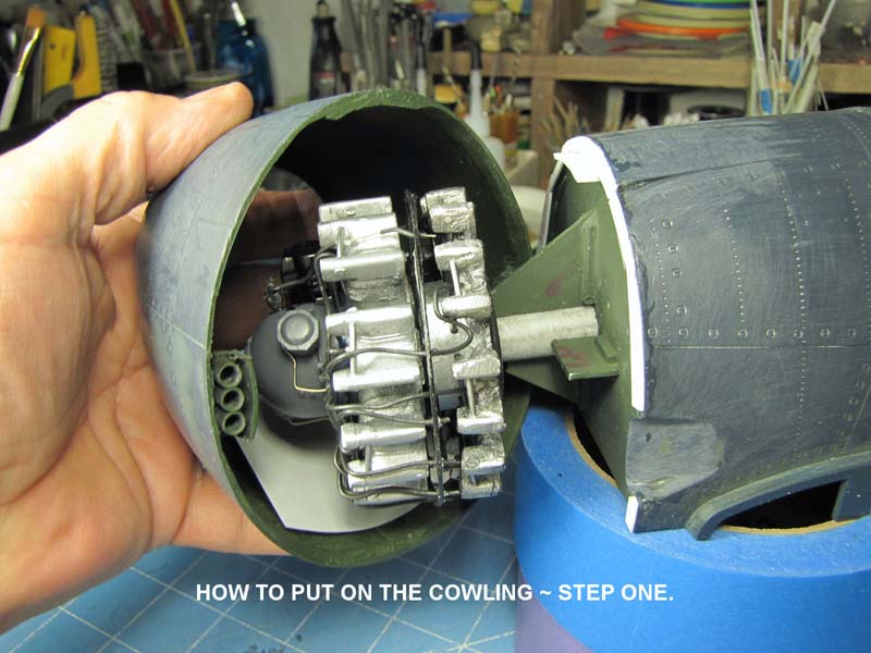
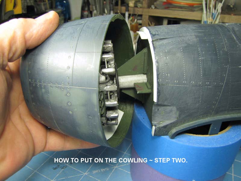
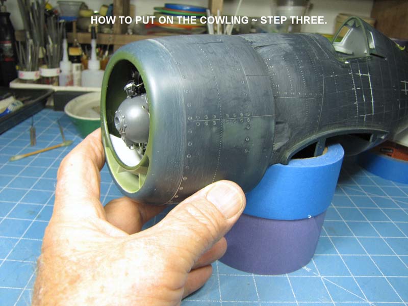
My last operation in this segment will consist of dry fitting on the cowling, once the engine is dry fit into its location.
Stay tuned to LSP for my next story on the "COCKPIT".
Part 1 | Part 2 | Part 3 | Part 4 | Part 5 | Part 6 | Part 7 | Part 8 | Part 9 | Part 10 | Part 11 | Part 12 | Part 13 | Part 14 | Part 15 | Part 16 | Part 17 | Part 18 | Part 19 | Part 20 | Part 21
© Rodney Williams 2010
This article was published on Wednesday, July 20 2011; Last modified on Saturday, May 14 2016