
Zactomodels | MiG-29A Resin Update Set
Reviewed by Ian Foulkes
Out of the Box onto the Model review of Zactomodels Mig 29 Fulcrum A Part 2 - The Underside
Well, on wards and upwards! As I have stated, these resin replacement parts are superbly well detailed and really add to the Revell kit. If you are making the Revell version then this set is an absolute must, and both together are still cheaper than the Trumpeter offering (at least in the UK). I decided to tackle the underside first.
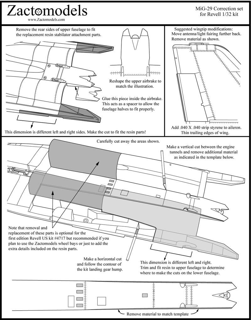
Insert 1 shows the Zactomodels instructions, which clearly show which areas need to be removed.
The resin replacement engine trunking stretches from the rear of the air intakes to the exhausts (with replacement exhausts in resin - again, the detail has to be seen to be believed). Each engine trunk comes in two parts, forward and aft. The instructions tell you to remove both sets of trunking from the kits underside. I would like to suggest a slightly different procedure. This is because I made a mistake and cut too much plastic away. (In picture 1 I have placed some black paper behind the parts to try and make the gaps show up more clearly.) Learn from my error!! Cut the engine trunking from the kit as per the instructions, but on the outside leave about 1/4inch ABOVE the undercarriage fairing along the whole length. Then cut and sand the outside to match the resin replacement parts. This will leave a good solid ridge of plastic for the resin parts to bind too. I failed to do this and you can see the results below, beside allowing the underside to be too flexible which made it a nightmare!
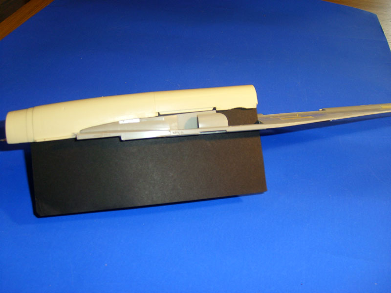
I had to insert a thick piece of plasticard to help secure the outside of the resin trunk to the lower kit fuselage and to act as a base for some filler. An excellent example of more haste less speed! Once both sets of the kits engine trunks have been removed, the fuselage between them can then be shaped according to Zactoman's plan. Having done this I set the underside to one side to cure and will leave it for about a week. At this stage I did not attach any of the details such as the additional air intakes, choosing to leave these until later to avoid knocking them off.
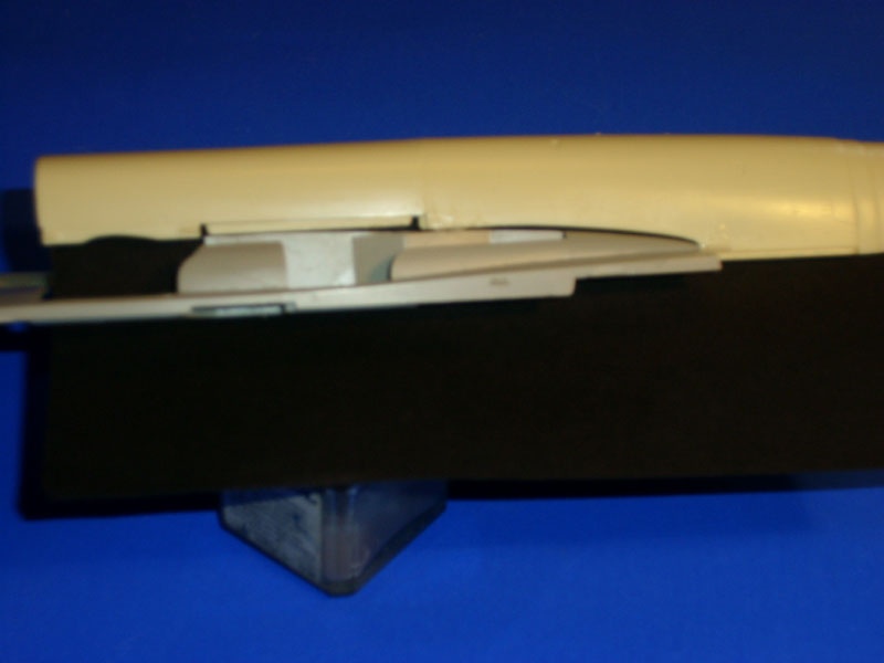
As you can see from both these pics, I managed to repeat my mistake on both sides. Dooohh! Again I have placed black paper to show up better the gaps I managed to make. Again, plasticard and filler to the rescue!
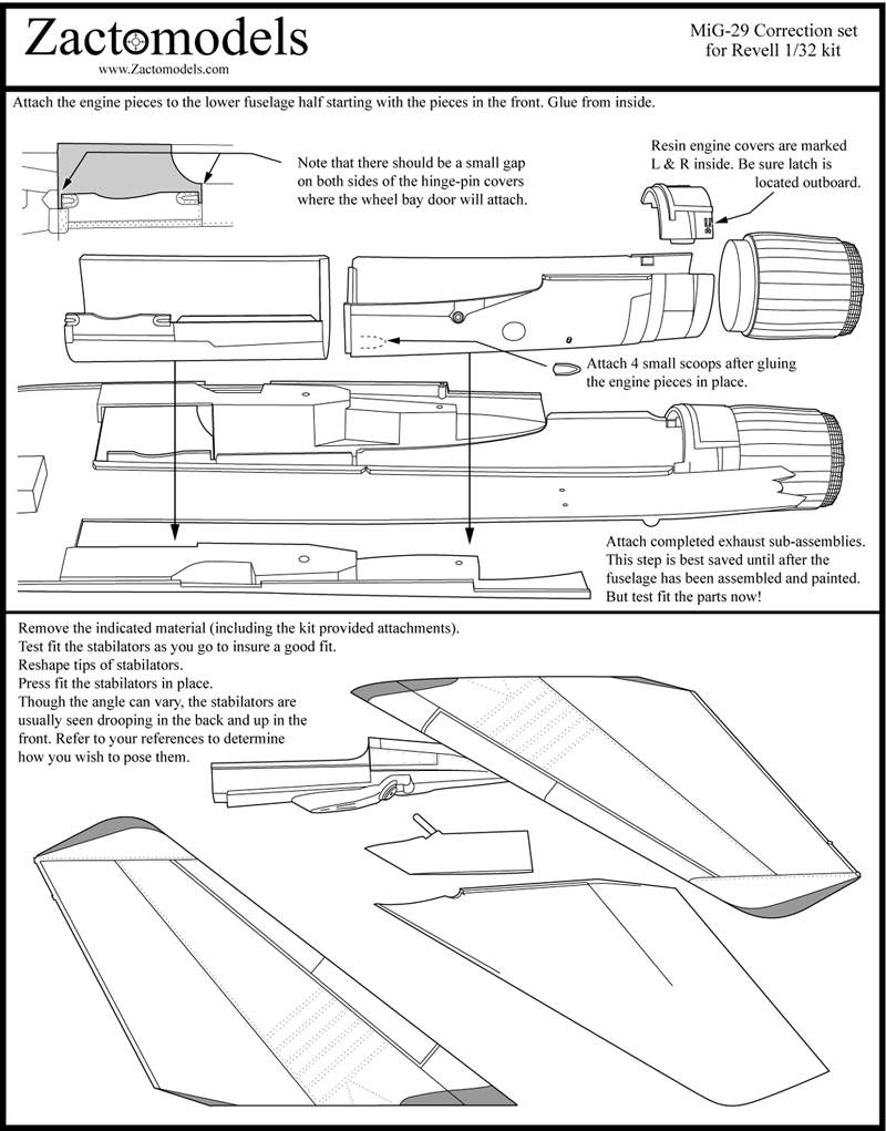
Putting the underside to one side to allow it to cure I turned my attention to the stabilators. This is a straight forward case of cutting, filing and filling. The kit parts have to be modified to accept the locating lug (a resin part with a brass rod sticking out) which will insert into the resin replacement hinge point on the fuselage. Then it is a simple matter of reducing the span of the stabilator. All the changes are clearly marked on the instructions, so again I copied them onto some card using a photocopier, cut out the stabilators pattern and then marked very carefully the areas to remove. I worked on the upper surface first, and then altered the underside to match. Insert 2 again shows the plans.
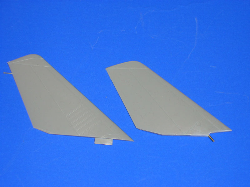
Picture 3 is a comparative shot of a modified and unmodified stabilators. As you can see it is nothing too dreadful!
© Ian Foulkes
This review was published on Saturday, July 02 2011; Last modified on Saturday, May 13 2017