
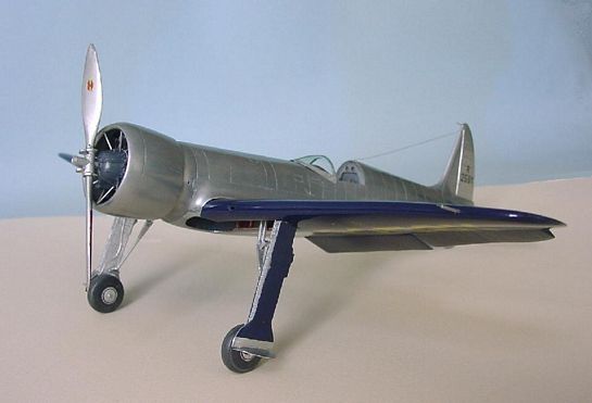
1/32 Combat Models Hughes H-1 "Long Wing"
By Gene Nollmann
History
Between the World Wars the "Golden Age" of aviation fostered an era of breathtaking air races and speed record attempts with names like Jimmy Doolittle and Roscoe Turner making headlines. When a French Caudron C.460 captured the Absolute Air Speed Record for Landplanes at 314.319 mph on 25 Dec 1934, the young and wealthy Howard Hughes, an avid aviator, reaffirmed his determination to complete his design for a plane to capture the speed record.
Personally funding the effort without commercial or government sponsorship, Hughes put together a small design team to include himself, aeronautical engineer Richard Palmer, and production chief Glenn Odekirk. With the utilization of the wind tunnel testing facility at Cal Tech, design and testing proceeded through late 1933 and 1934 culminating in the construction of the Hughes H-1.
Contemporary to the Hughes H-1, were the Boeing P-26 Peashooter (first entering Marine service early in 1934), the Beechcraft Model 17 Staggerwing (first flight 1934 and acknowledged as a very fast plane). The Mitsubishi A6M Type 96 "Claude' first flew on 3 Feb 1935.
The Hughes H-1 Short Wing's first flight was 17 Aug 1935. 27 days later and with less than 5 hours on the log, it captured its FAI certified Absolute Air Speed Record for Landplanes with an average run of 352.388mph on 13 Sep 1935.
The H-1's record stood 27 months when it was raised 27 mph on 11 Nov 1937. Messerschmitt, with his government's financing, broke the H-1's record with an average run of 379.627 mph in a race-engined and 'cleaned' Bf 109 V13. The Hughes H-1 would be the last non-military derivative plane to hold the record.
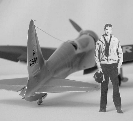
Hughes had set his air speed record in a "Short Wing" version of the H-1 (wingspan of 24'5"). Being an active long distance pilot and pioneer, he wanted to also set a Transcontinental record in the H-1 and proceeded to design the "Long Wing" version (wingspan of 31'9"). Essentially the same fuselage with improved instrumentation for cross-country flying and with a redesigned wing for greater lift and fuel capacity.
The year-old plane was ready for flight testing and finally departed Los Angeles 19 Jan 1937 and landed in Newark 7hr28m25sec covering the 2490 miles with an average speed of 327.1mph. Completing the 7.5 hour non-stop flight at 93% of his short run speed record! (Wonder if the Bf 109 V13 could have done that?).
Design Innovations
The H-1 was not simply a plane built to attain a speed record. In researching for information to build a replica of the H-1, the Wright Machine Tool team discovered the plane had too many features and innovations to be just a single-purpose record plane-it was also a 'technology demonstrator' for future aircraft. But all the innovation was kept a secret within the Hughes design team. Some of the firsts the Wright team uncovered were:
- For take-off and landing, the plane used split flaps and a corresponding aileron droop of up to 15 degrees to be able to have altered lift across the entire wing,
- Wing leading edge air-duct intakes,
- jet-thrust exhaust,
- Hydraulically actuated landing gear,
- Fuselage panels were butt finished, not lapped,
- All fuselage fasteners and rivets were flush,
- Pilots seat raised to give better view on take-off and landing.
The Model
Long ago one of the historical aircraft magazines ran a piece on the Hughes H-1 complete with drawings and outboard surface sections. Elsewhere there was a photo of a very nicely done 1:32 scale model of the plane scratchbuilt by Ralph McQuary (one of the well-known illustrators on Star Wars). The seed was planted.
Then more recently I stumbled across the news that someone was in the process of building a replica. Some research on the web turned up The Wright Machine Tool Company's webpage on Jim Wright's project. They showed some views of the plane under construction. They completed the project and had their initial flight 9 Jul 2002.
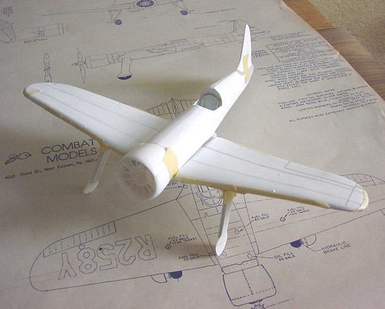
Combat Models
Combat Models' rendition of the Hughes H-1 Long Wing comes on a single vacuum formed styrene sheet and with a drawing showing three views of the plane. The vac sheet did not appear to be very snugly pulled into the form, evidenced by generous amounts of 'draping' where crisp corners would be expected. The wing was provided as left and right, upper and lower halves, the fuselage as left and right halves integral with rudder, separate left and right cowl halves, left and right wing root fairings, left and right, upper and lower elevators, and a single piece clear windscreen/canopy. Sometimes included in vac-kits (although usually not useful) but not included in this kit were the seat, a dummy engine front, propeller, wheels; all would have to be devised from other sources or scratchbuilt.
A caution to one who might have one of these kits: each view in the drawing supplied was a slightly different scale, i.e., the wingspan in one view didn't match in another view, etc. A very good drawing source are the 3-plate set of drawings done by the late Paul Matt and available in 1:24 scale or on CD with some photo reverence (and a bonus of several other planes) from Aviation Heritage Books or Wind Canyon Books.
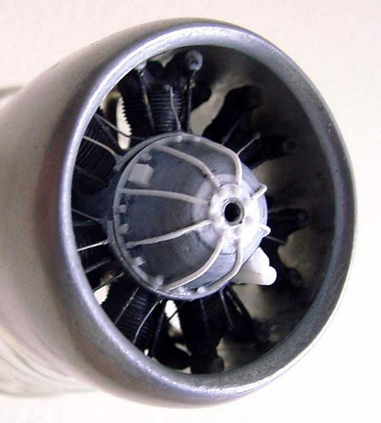
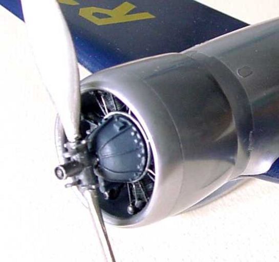
The Engine and Cowl
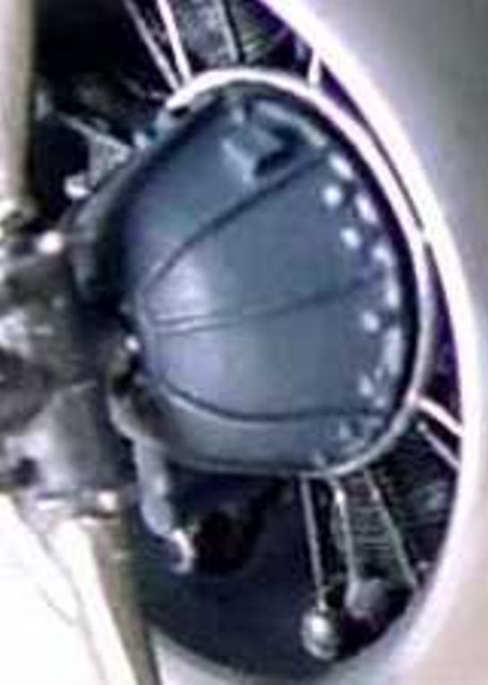
Fortunately for the scratch and vac builder, Williams Brothers offer 3 different "Golden Era" type radial engines in 1:32. The Hughes H-1 used a Pratt & Whitney Twin Wasp Junior rated at 900 hp on 100 octane, so the Williams Bros. #31000 P&W "Twin Wasp" is a good basis. However the Williams conical engine front does not resemble the rounded and ribbed engine front of the Twin Wasp Jr. used on the Hughes.
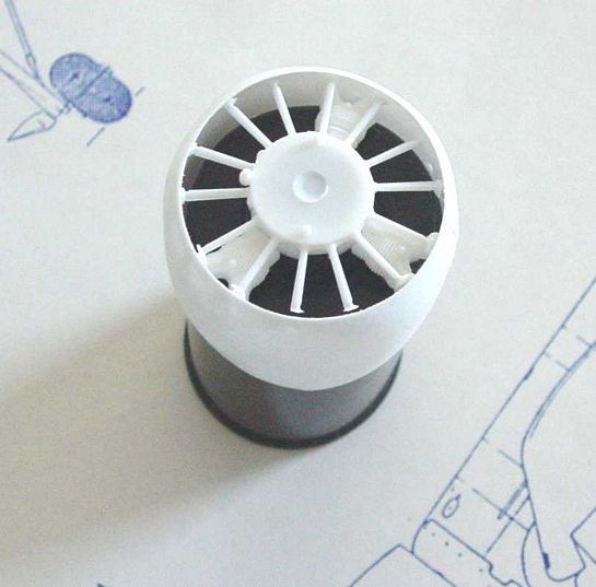
For me, the acid test question was, "will the Combat Models cowl properly fit the Williams Bros. engine?" A quick mock-up of the engine very snugly slipped into the cowl and encouraged me to continue.
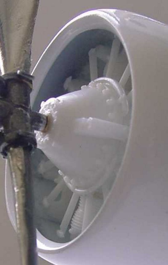
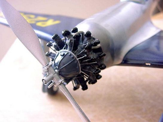
Using the Williams Bros. Kit engine front, some Tamiya grey putty was applied in coats allowing each to thoroughly dry, gradually building up to the desired profile resembling the Hughes H-1 engine front. After the putty was dried the engine nosepiece was centered and glue to a shaft which in turn was fastened into the end of an electric eraser (my low-tech lathe). The unit was turned down to shape, polished and then strip styrene applied to represent the ribs and attachment bolts represented by pieces of plastic rod. The William's pushrods suffered from tired injection molds (the front half and back half of the rods were misaligned) and were replaced with brass rod. Ignition wires were made from 30 AWG insulated wrapping wire with the insulation stripped off. A .063" dia. soldier was used for the exhaust pipes. Finally mounting rods were installed which give the cowl/engine assembly the H-1's characteristic deep-dish look.
Prop
The prop for the Hughes was rather large for the size of the plane, a 10'0" diameter Hamilton-Standard. Using 2 blades of a Roberts Model 3-blade kit of a 10'6" Hamilton Standard prop, a new hub was constructed with counter-weights etc., and married with the slightly shortened props. The hub seems very large, but photo reference supports the drawings and the final appearance in the model.
Prop blades were sanded to near gloss and given a couple of coats of Future and then some Metalizer and polished. This rendered a very convincing finish until the application of decals somewhat marred the final finish. The Hamilton Standard logo was cannibalized from some extras in another kit. A lot of frustration ensued with the decal clear carrier and the finish of the blade. Ultimately the clear carrier had to be trimmed away down to the edge of logo; the remaining decal was applied with a droplet of Future with the excess rapidly wicked away and not allowed to set on the metalized surface. One of those situations where some lessons were learned, but real solutions not yet developed.
Instrument panel
Photo reference on the cockpit was quite sparse; the instrument panel seems to have intrigued most editors, so I was able to find reasonable reference to mock-up an instrument panel using Waldron's American Aircraft Instruments to guide overall sizing.
Seat
In the absence of any good reference of the Hughes seat, a seat was built-up from thin styrene sheet making one similar to a P-40B's that I was working on and added some Waldron Standard Seat Belts Buckles.
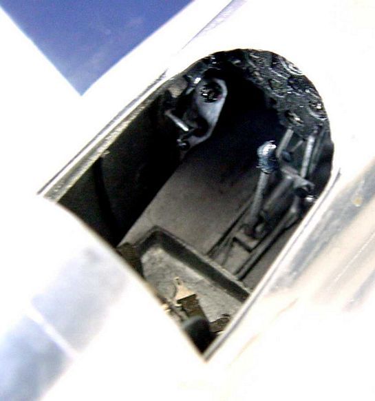
Other Interior Elements
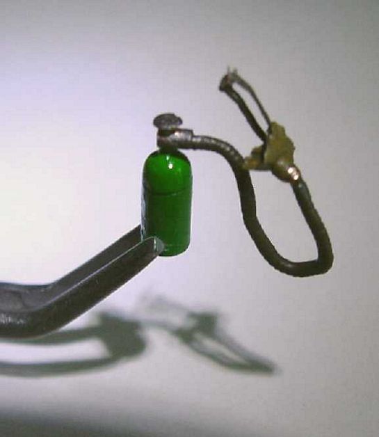
Rounding out the interior were scratchbuilt rudder pedals, control stick, throttle quadrant, fuel tank balance/switch levers, left and right window crank handles, and various control knobs below the instrument panel. Above the instrument panels were several pieces of padded cockpit combing (in this case made of clay and painted with Liquitex).
Canopy
The center section of the actual canopy splits in the center and slides down into fuselage side pockets and to further ease egress, the front portion of the canopy can slide forward (and the seat can be raised to enhance visibility during take-off and landing). In my sparse reference, exactly how the center sections slide and where it goes remains a mystery to me, although one reference does state they went down into the cockpit.
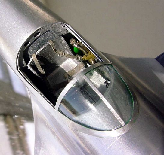
For the model, the side panels have slid out of view and only the windscreen remains! The Smithsonian example seems to have a slight greenish tint to the windscreen and the Wright replica certainly shows a tint. To accomplish this some Tamiya X-25 Clear Green was diluted with Future to give the interior surface of the windscreen a thin wash of color. The windscreen itself was reformed over a new plaster plug. The kit supplied canopy had the window frames molded in and had the incorrect overall shape. A heavy aluminum foil was cut to form the frames and applied to the newly trimmed windscreen. It was in preparation for making the canopy that I finally realized the vac fuselage cockpit opening was cut about a tenth of an inch lower than it should be (representing a substantial 3.2" of actual size!!). Since the low profile was such a significant part of the 'look' of the plane, I went ahead and added to the windowsill to more closely conform to the actual aircraft. Not a happy thing to do when so much cockpit and fuselage work had been near completion.
Fuselage
In my process of building vac models I've developed a habit of taping the trimmed and sanded fuselage halves together and filling it with plaster (Plaster of Paris works just fine). With the plaster plug removed, I can cut it any place and develop a bulkhead or fuselage rib to help stiffen the final assembled fuselage. I particularly enjoy seeing how these simple ribs and bulkheads glued to the fuselage skin will stiffen the whole structure bringing the model building process closer to the structural principals involved.
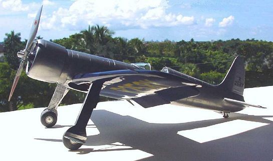
The assembled fuselage was painted overall gloss white, the thought at the time that a white base would enhance the overpainting of metallic paint. I'm not convinced that was the case, but the gloss white certainly allowed the overpainting Model Master #1451 Aluminum Plate (Buffing Metalizer) to be polished to a nice luster. Unfortunately when sealed, the luster disappears. Also used to accent some areas were some #1453 Magnesium (Buffing Metalizer), and some #1402 Stainless Steel (Buffing Metalizer.
And then I polished too far, that is, down to the base color; to recover, I gave the metalized finish an over coat of Future and then a fresh coat of Metalizer. In the future, I expect to use the Future as a polished base coat, I think it will work very well. However, the only way to get the shine of the Replica H-1 would be to have a thick metal foil on the fuselage to polish with a lot of ElbowGrease.
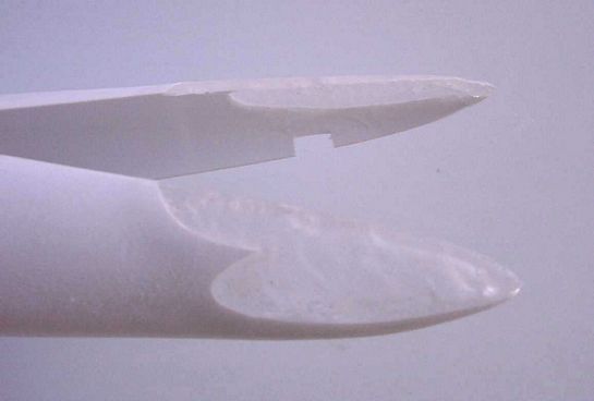
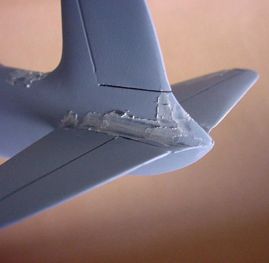
Rudder and elevator
Using the vac fuselage, I could see that if the fuselage were trimmed to represent correct fuselage width then the integral rudder assembly was going to be too thick (from tip to root), so I removed the rudder and also removed the poorly formed fairings for the elevators; then bridged the openings with a build-up of Cyanoacrylate. Properly sanded and primed this allowed a good surface to be developed so I could later attach the properly thinned rudder and elevator.
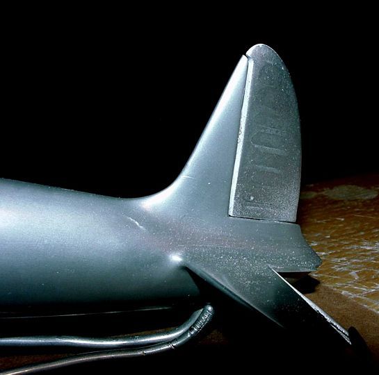
Ever notice, no matter how much block-sanding you do, a serious paint run never seems to be completely sanded away? It occurred to me that this could lead to an advantage when subtle surface variation is desired.
The trailing surfaces of the rudder and elevator were fabric covered over metal frames. This lead to the telltale slight fabric shrink below the line of the ribs. The effect is subtle, but quite noticeable. To accomplish the effect, I taped the areas to be represented by the unsupported fabric and trimmed away the tape wherever a rib or other structure would occur. Then Tamiya putty filler was applied to the trimmed away area up and over the tape. When dry, the putty was sanded down to the tape, the tape was then removed, and then further careful sanding proceeded always allowing some expression of the putty to remain (like that lesson of the paint drip never disappearing!). The additional sanding was required to soften the edge after the tape was removed. With an overall coat of paint the surface resembled a fabric covered metal structure.
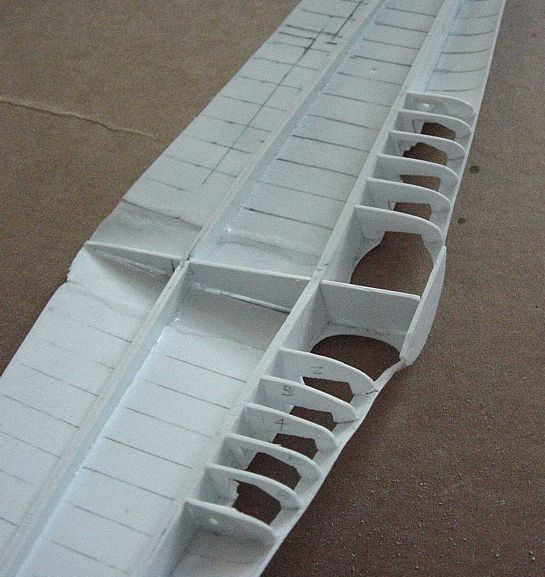
Wings
The actual H-1 wing is wood: plywood spars and ribs and the assembly is sheathed with plywood, sealed and given an extraordinary smooth surface. With the wheels down, one can glimpse and marvel at the materials and construction method. With the flaps down, more plywood is revealed in contrast to the all aluminum flaps. All these details make for an interesting modeling challenge. Various sources have an old black and white photo of the bottom of the wing before sheathing and the Wright Machine Tool H-1 website is a very good source of the wing construction process. I found no specific drawings of wing rib profiles through the split flap and wheel well areas but the photos help to make reasonable guesses as to shape and location.
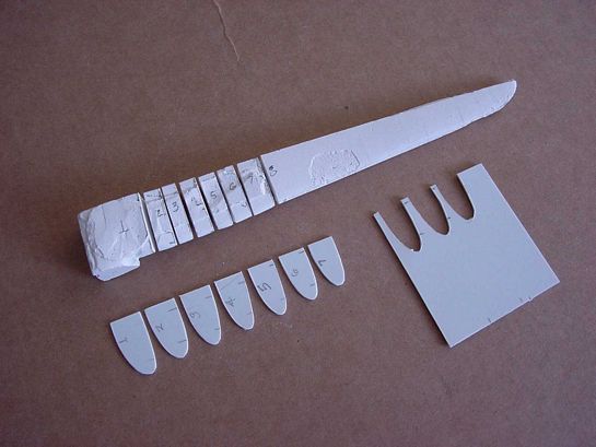
Wing Rib Profiles
Casting plaster was poured into the taped together wings; the dried plaster was cut into sections to get the rib profiles to create the sections spanning the wheel well, and spanning the upper surfaces of the split flaps. Reference to photos where used to refine the interior shapes of the ribs.
Flaps
With the lower panel of the flap carefully trimmed from the wing, very narrow angle wedges of sheet styrene were applied to make the proper flap section. The inner panel was perforated with holes using the Waldron Punch and Die set.
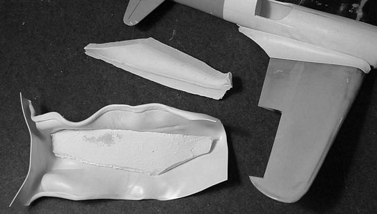
Wing fairing
The left and right wing fairings supplied with the kit were not mirror image matches. My solution was to sculpt more symmetrical shapes on the model in clay, cast plaster against the assembly, and then heat sheet styrene and pull over the form by hand. (A poor-man's vacuum form! And a technique that may be more familiar to those who have formed canopies with Squadron's supplies). The pieces were trimmed and attached to the fuselage and then blended in flush.
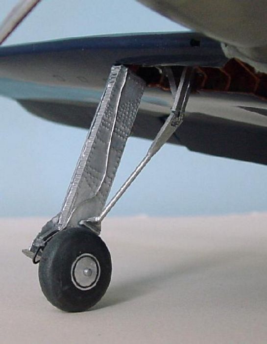
Landing Gear and Wheels
With the gear door covers carefully trimmed from the vac wing, a thin sandwich of styrene was built up to simulate the unusual landing gear of the H-1. With the gear down, the interior surface of the gear 'sandwich' is covered with hundreds of raised rivets; this was accomplished with embossing the backside of a piece of heavy aluminum foil and then gluing to the strut main body.
Wheels are from Williams Bros. #13600 3/4" dia. smooth contour wheels; out of the package their shape and diameter were not quite close enough, being originally intended as tailwheels for much larger R/C aircraft. They were lashed up to my 'poor man's' lathe and scrubbed down by running over sandpaper until the desired diameter and profile were achieved. Then some hub detail was added and painted.
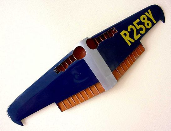
Painting and Markings
The plane has appeared with several different registration numbers. NR258Y first appeared on the Short Wing, later NX258Y. By the time it came to rest in the Smithsonian the number was simply R258Y, which is how it appears in Paul Matt's drawings. The Wright replica uses NX258Y.
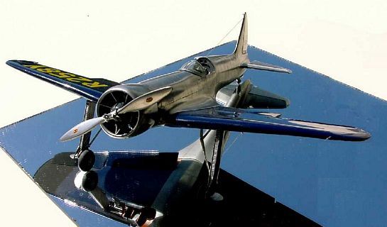
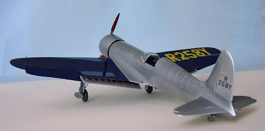
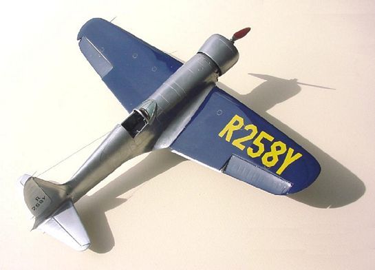
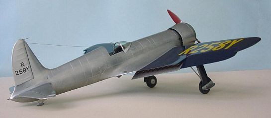
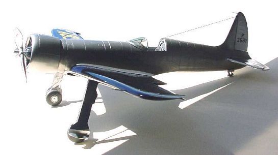
Because Hughes did not need commercial sponsorship, the plane's markings were very simple: large registration numbers in chrome yellow on the top and bottom of the dark blue wing and black registration numbers on the silver rudder.
For the wings I cut the numbers from Experts-Choice # CF-2 Chrome Yellow decal sheet. In retrospect I wish I had airbrushed additional color onto the sheet to increase color density.
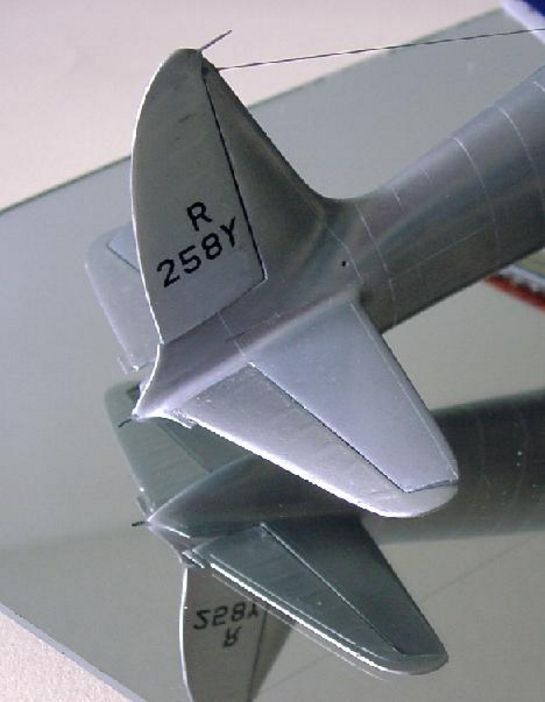
The rudder markings are cobbled together from Eagle Strike's #48048 US 45 Degree ID Numbers & Letters (Black). This is a great 2-sheet set of numbers and letters, although aimed at 48th scale, many items in the collection can be adapted for 32nd uses and one of the sizes was perfect for the H-1's tail codes. I said cobbled because there were no letters the same size as the numbers, so a '7' was cut and adjusted to become the 'Y', and a '5' and part of a '2' became the 'R'.
Wings were painted with Tamiya's X-3 Royal Blue (gloss) and after the decal application, sealed with Future Premium Floor Finish.
Under wing openings that expose the interior wood construction, that is, the wheel wells and the split flaps, were primed with a coat of Model Master #1735 Wood. This paint seemed to have just about the right ochre color to simulate the yellowish quality of the plywood used in the Hughes replica (at this point in time, the Smithsonian's H-1 plywood has taken on the look of very old dark wood and doesn't have a fresh look of the replica). Several experiments led me to the conclusion of sealing the base-color with a mist coat of Testors Dull Cote and then dry-brushing with an overcoat of Liquitex #2002-127 Burnt Sienna The use of Liquitex is a little diversion from my normal paint palette, but it did allow clean color separation and the 'read' of wood grain plywood similar to the reference. Using a wood tooth pick, the Liquitex was easily 'rolled' off the surface of the sealed under coat to reveal the light color wood on the butt ends of the cut plywood just as in the reference.
Conclusion
As I was wrapping-up the finishing touches to the model and this article I learned of some very sad news indeed. An AP-wire notice indicated the H-1 Replica had crashed in Yellowstone on Monday the 4th of August at 6:30 PM MST as it was returning to its Oregon home from a week at the Oshkosh festivities in Wisconsin. It said the pilot had been killed.
It is quite an heroic venture to research and build a replica of an historic plane such as the Hughes H-1 and yet another leap of heroism to venture to fly the plane. Jim Wright and his team brought us fresh view of the Golden Era's vision of the future through their recreation of the Hughes H-1 and their reenactment of the pioneering dreams of flight. Howard Hughes flew the H-1 cross-country and would dedicate some of his life bringing dependable commercial flight to the public. Jim Wright's sacrifice is a sober reminder of the real stakes and dangers the pioneering spirit faced to bring aviation to the seemingly common place event that it is today.
As for the model, the Hughes H-1 offers many surprising and interesting challenges - it would probably be a popular multi-media resin kit.
References:
- Scale Model Research - photopack #3750(12)
- The Hughes H-1B at the National Air & Space Museum - Golden Era Display
- The Paul Matt Collection - Archive 3
An Aviation Heritage CD-ROM, c2000. - Wright Machine Tool Co. Inc. website
- All Aviation FlightLine OnLine -- World of Wings -
Hughes H-1 Racer - several installments of build process
Air & Space, May, 2003 - "Silver Bullet: Jim Wright built . . ." "Hughes Racer II"
By Preston Lerner - Air Racing, Air Classics Special, Vol. 2, 1993.
- 'Howard's Magnificent Racer" by Don Dwiggens
3-view drawing with sections by Harold A Osborne
© Gene Nollmann 2003
This article was published on Wednesday, July 20 2011; Last modified on Saturday, May 14 2016