
Dressing Up the Revell 1:28 Spad XIII
By Steven Perry
Dressing Up the Revell 1:28 Spad XIII
with Copper State Models Decals and Details
Introduction
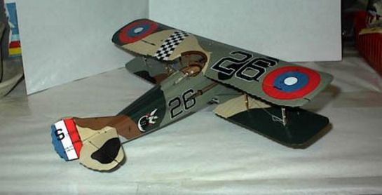
The story of Frank Luke was the first WWI story I ever read as a kid. Sort of got me hooked on the whole era. You just have to love somebody who can flout so many rules that the only things "Management" can think of to do to him are to award him the Medal of Honor and name an air base after him.
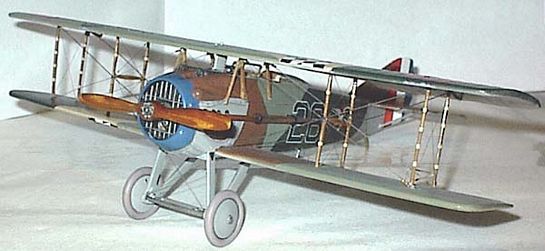
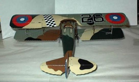
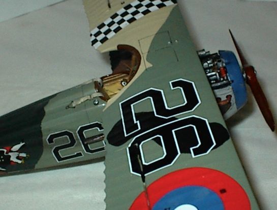
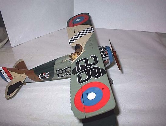
My stepfather bought this particular kit new in 1965, the year this version in the flat white box was released. I have wanted to do it up as Luke's #26 ever since it was given to me a few years ago. I knew I'd hit the jackpot when I was at the 99 Nats in Orlando and came across the Copper State Models table. All sorts of 1:28 scale goodies for my old Spad. I picked up a Spad detail set and a Frank Luke decal sheet. Later when CSM had a sale, I bought the French Instruments, Nuts & Bolts, Prop Bosses and Vickers guns PE sets.
One last item remained for this project and that is the fact that Luke flew a Bleriot manufactured Spad with the squared off wing tips and the Revell kit is of an early Spad machine with rounded tips. Fortunately in this case the Revell Spad is a little over scale. Simply sand the tips to the squared off planform shown in the Datafile drawings. You lose just about enough to make it right. Knock a millimeter or so off the leading edges and you will be real close to a pair of 1:28 scale, square tip Spad wings.
This article will cover the assembly of the Revell Spad and the addition of all the available CSM detail parts as well. I followed the assembly sequence indicated on the instruction sheet, except for a few areas which I will note. I used the Spad XIII Datafile as my primary reference as well as the Squadron In Action book and profiles by Bob Pearson.
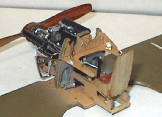
Engine
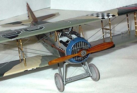
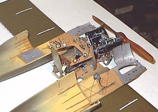
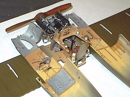
I began construction by assembling the Hispano Suiza engine. This replica has 15 injected parts and is very highly detailed for a kit of this age. The older technology leaves ejector pin marks in many parts and that includes the cylinder bank pieces. These are a nuisance to clean up, but tell yourself that it builds character and get on with cleaning up the pin marks.
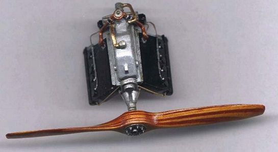
Use care to trim and dry fit the pieces. Fit is not this model's forte. Pay special attention to aligning the case pieces (4L & 3R) that the cylinder banks attach to. If these are not aligned right the cylinders sit at an angle and cause major fit problems later. The engine is pretty complete as it is. I added CSM nuts and bolt heads to a few prominent places on the carb, manifold and gear reduction case. I painted the cylinders flat black and the case aluminum. Various details were picked out with steel, silver, brass and copper paints by Testors. The only details I added myself are the plug wires that go from the plug wire conduit molded on the cylinders to the magnetos and the oil lines that run up the front edge of the cylinder banks. The plug wires I made of copper armature wire and painted a brownish color and the oil lines are from heat-stretched sprue with a CSM washer as a fitting at the upper attach point.
Propeller
The Martin Digmayer hand-carved props that CSM makes available are simply gorgeous. CSM makes a fret of prop bosses that are just the ticket for this item. The prop bosses have a central hole and two concentric circles of smaller bolt boles.
First off, the Revell Spad prop shaft is a bit large in diameter for the hole in the boss. You can file or sand the shaft or ream out the hole in the boss with a sharp #11 blade. Once both bosses will fit over the shaft, the center of the prop hub needs to be determined and a hole the diameter of the shaft needs to be opened. Use a pilot hole and drill through from the front to avoid splintering the exit hole.
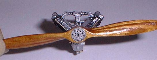
The safe way to do this, (you guessed right, I did it the other way), is to add the bolt details to the bosses before attaching them to the prop. On the back plate, stick eight of CSMs solid bolt heads, one over each of the eight outer ring of bolt holes. In the front, stick eight of the open centered nuts. Then with a piece of heat-stretched sprue, cut eight pieces about 1/8 inch long. Stick one of these in the center of each nut. I dipped the end in CA and just stuck the piece straight in. A drop of CA kicker when they are all in place helps ensure the CA has set. Nip the "bolt shafts" back to just a bit above the nuts. As a final touch in this huge scale, I used a piece of copper armature wire to simulate the safety wire between the bolts. A drop of steel paint and a wash in india ink finishes the bosses. A couple of coats of Future is all that is needed to finish off the prop blades.
In the photos I have seen of Spad prop hubs, the central shaft protrudes out the front a bit past the bolts. The shaft is hollow so you will have to drill it out. I used a fine pilot hole and then twisted a #11 blade point in the hole till the opening was the right size. Easier than trying to open it that wide with a drill bit.
Diverging from the Instructions
The Revell instructions would have you glue the fuselage halves together, assemble the seat/firewall/engine bearers unit and then drop that in place after gluing on the lower wing.
This will not work if you are going to detail the cockpit. Build the engine bearer assembly directly on the lower wing. Be sure all the interlocking pieces fit completely. You will need to trim to achieve this. You can work the two fuselage halves around the interior structure and fit them together with a slight twist. Don't worry you will fit them together and take them apart a bazillion times as you work through the detailing process. Practice makes perfect. By the time you get delicate sidewall detail on, you will be well practiced at the manoeuver.
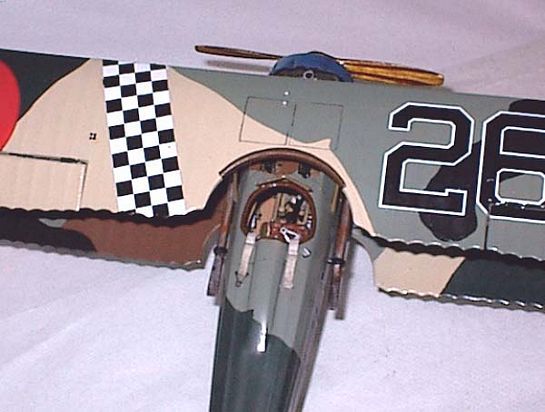
With this basic change in assembly order, you will be able to have access to all parts of the interior as you build in just the amount of detail you want. I will outline the order of things where it is important, but first it's time to discuss the facts of life concerning Revell's 1:28 Spad. Fact one. This sucker ain't exactly to scale. It may be a bit oversize, almost 1:27 scale. Accessories made for it may not be to exactly the same scale. Fact two. Spads were built by a whole herd of contractors and licensees. The office is one area where manufacturing variations are likely to abound. Fact three. Spads were sent to many different services in many countries. Cockpit mods, official and custom, are the rule, not the exception. Fact four. The basic design common to all Spad cockpits is, IMAACO (In My Arrogant And Conceited Opinion), the most difficult WWI scout office there is to model. The ah, "more retentive" amongst us are advised to scratchbuild their own interior to their own standards and satisfaction. For those of us who want to take a kit we have seen around all our lives and "dress it up right", the detail sets available from Copper State Models will provide an enjoyable challenge with a satisfying model as the result. Perhaps not museum accurate, but a quantum leap ahead of just the kit.
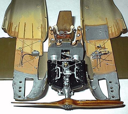
Since the Spad interior is so detailed it is best to build it in three main pieces and those built up in "layers" of details. The central piece built around the engine bearers and lower wing and the two fuselage halves with their sidewall details make up the trio.
Begin the central structure with the engine bearers, parts 29R & 30L. I had several photos of Spads in various stages of reconstruction. No two are exactly alike in all aspects, (imagine that in this hobby). All were wood with access holes and metal reinforcement. Trim the locator "logs" so they fit all the way down into the holes in the lower wing. Paint the bearers, lower wing center section and firewall a base color of wood. Simulate the metal reinforcements with paint or foil. I used a bit of each. Wood grain can easily be simulated with a watercolor pencil.
Next comes the firewall. Remove the hump on the center and the locator logs in the lower corners. The rim around the piece is supposed to be some of the wood structure so that is why I said to spray it wood along with the other pieces. Paint the lower surface on the cockpit side aluminum and the upper portion leave wood . It will be covered by a PE piece from the CSM detail set.. The engine side is all aluminum. Trim the notches in the firewall (36) and those in the bearers so the firewall locks in and fits flush with the surface of the lower wing center section.
Before you glue the firewall on it needs slight modification in order to work with the CSM PE instrument shelf. On the cockpit side, locate the raised horizontal ridge that is just below the gun cutouts. The hugely thick kit piece mounts below this ridge as evidenced by the two locator tabs. The CSM piece needs to rest along the top of this ridge. In order for it to do this you will need to notch the vertical edge ridges where they intersect the top of the horizontal ridge. The CSM shelf is exactly as wide as the firewall, so the notches let it sit flush with the firewall while resting along the top of the horizontal ridge. Don't glue on the shelf yet.
Fit, but don't yet glue the trimmed, notched and painted firewall in place on the engine bearers and lower wing. At this point I added the front cowl supports and attached the engine. Now to begin the layers in the cockpit. First is between the bearers. The rudder bar and folded X support will occupy the front portion of the space between the engine bearers.
One of the few things I found lacking in the detail set is the X support for the rudder bar. Make one from 5 thou card and fold it over without kinking it. Wrestle this into place above & below the rudder bar and between the engine bearers. Did I mention to paint it aluminum and let it dry thoroughly BEFORE you attempt to install it.
The fuel line, rudder control cables (two each side), the joystick support frame and a wooden mallet used for beating on a jammed gun make up the rest of the detail between the bearers. The fuel line I made from fine brass wire with parafilm rolled around it to achieve the proper diameter. It is painted aluminum, the wire core lets it be bent and hold the shape. This is essential to the wild run this pipe makes in the photos.
Rubber connectors can be made by white gluing a narrow strip of paper and wrapping it around the pipe to further increase the diameter. Paint this a rubber color and paint two silver stripes around to simulate clamps. Make the mallet out of bamboo & toothpick. Simulate chain and attach clamps if you are so inclined.
The next layer of detail in the central structure is the, seat, joystick and shelf. The kit seat is completely inaccurate, I made one from 1/64 plywood. Use ammonia to loosen the fibers of the wood on the outside in order to get the proper bend in the back piece. I blatantly cheated on the seat cushion. I have a Poucher Caudron G.3 kit and that includes molds for pressing a pattern into material to make a seat cushion. I pressed a piece of plastic foam gotten from a plastic figure 8 packing peanut between the mold pieces and a perfect seat cushion resulted. I just cleaned up the kit joystick and thinned out the base where it attaches to the support frame. A gun trigger wire can be draped between the joystick and the firewall under where the shelf attaches. Finally add the shelf. Make sure it is at 90 degrees from the upper portion of the firewall. Fit the vertical piece to the firewall and bend in a curve to match the photos in the Datafile.
The final layer of detail on the central structure is the instruments on the shelf. The CSM French Instruments are perhaps a bit small, but they are exquisitely detailed. Paint the back side of the film white. When this is well dry, cut out the dials. "Yeah right Bub, those suckers are less than a quarter inch in diameter, why the whole film piece is about three quarters of a square inch." Easy, with a sharp #11 blade, carefully separate a dial face from the sheet. Make the cuts by laying the edge of the blade on the surface of the film and pressing directly down making a long single cut in one "click". Make similar cuts just tangent to the circular face of the dial. You will leave little points of clear plastic around the circular dial. Attach to the Photo Etched beezel with white glue. A damp toothpick end will clean up any glue from the face of the dial. Add instrument bodies from styrene rod or sprue and paint brass or aluminum and attach them to the instrument shelf as per your references.
The sidewalls are layered in detail as follows. First paint the inside wood and Clear Doped Linen as appropriate. Now add the vertical pieces of wood (these actually run at an angle). These pieces are rather deep and curved as they also act as formers to the rounded fuselage side. Also add the longerons and stringers. You can use styrene strip or actual wood. Look on the outside surface detail for locations. Next layer is the cable cross bracing. I used surgical steel and Grandt Line turnbuckles. Lines and wires to instruments come next and the final layer is the compass and throttle quadrant on the port and a blower looking box on the starboard side. This will have to be scratched. The Datafile provides some excellent photos of cockpit interiors.
Tailfeathers
The Revell Spad has wonderful detail in the tail surfaces. There is a gap and hinges already there. No need to cut away and reposition these. I took a strip of sanding film and slipped it between the gaps and cleaned them up leaving just the hinges. Then I simply bent the surfaces to the deflected position. Gently. I also trimmed away the locating pin that goes into a hole in the horizontal tailplane piece, leaving the tab that fits in a slot in the fuselage. It sits better this way.
Final Assembly and Finishing
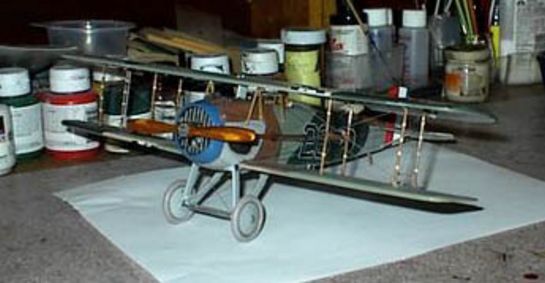
Once the cockpit and engine bay were detailed to my satisfaction I worked with the top cowl so it would slide on and off under the guns. This took some filing, sanding and adding bits of card then more filing and sanding until the fit was correct.
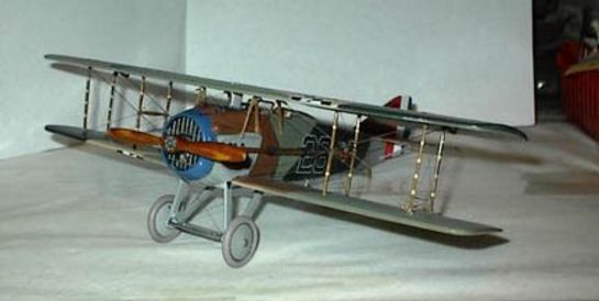
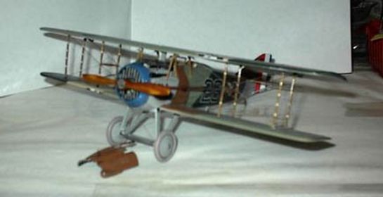
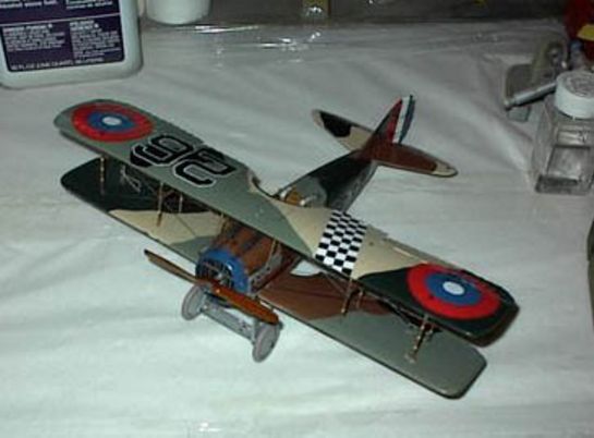
The tail feathers went on without trouble as did the landing gear. This left the struts and the top wing to assemble. Painting and decalling had to be done before the final assembly and rigging.
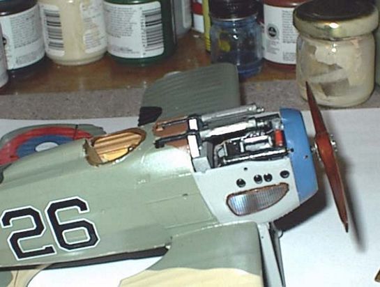
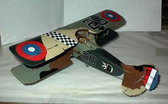
I painted the bottom surfaces a light gray. And immediately showed up all sorts of imperfections in the seam work. These were dealt with and another coat of paint applied. I began the 5 color French camo with the beige color overall the top surfaces. Then with Parafilm, I masked and sprayed the other colors, light green, brown. dark green and black. All my paints were Liquitex acrylic mixed with Future.
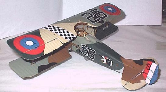
The Copper State decals for Luke's machine went on next. Use care as you blot them, they become a bit stiff and are prone to rip as you blot them. They reacted reasonably well to micro sol and ended up settling down nicely.
I have no use for the kit struts. I made the mistake of trying to correct and use them. Save yourself time and trouble and scratchbuild the struts from bamboo. The kit struts just do not lend themselves to cleanup with the giant holes for sewing thread rigging molded into them.
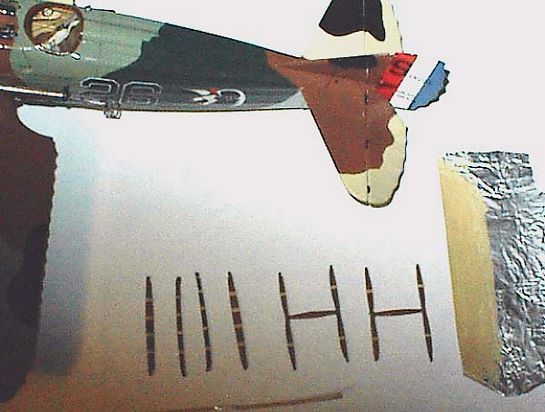
Rigging was a combination of stretched sprue and stainless steel wire. This was the only part of the model that I didn't like. I will never use anything but stretched sprue for rigging again. Nothing works as well for me.
After the top wing is finally mounted you need to make the fuel and water line pylon from the upper wing. I installed the lines made from wire and then took a piece of .005 card and bent it around the lines so as to form the airfoil shaped fairing that was characteristic of the pylon. A final light coat of dullcote to tone down the gloss and the model was finished a scant 35 years after it was purchased.
Conclusion
The old Revell kit has as much model in it as you are willing to extract. This is a kit that rewards the modeler who puts some work into it. The Copper State decals were a necessary addition to replace the disintegrated (as well as inaccurate) originals. The detail kits available through Copper State Models do a great deal to dress up the old kit and are highly recommended.
Steve's SPAD first appeared in the Internet Modeler January 2002 issue.
© Steve Perry
This article was published on Wednesday, July 20 2011; Last modified on Saturday, May 14 2016