
Hasegawa 1/32 Spitfire Mk II
By Max Otten
Introduction
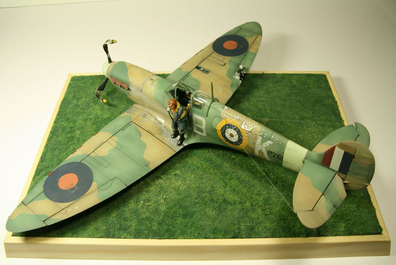
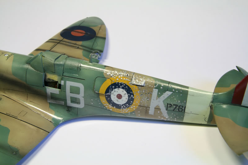
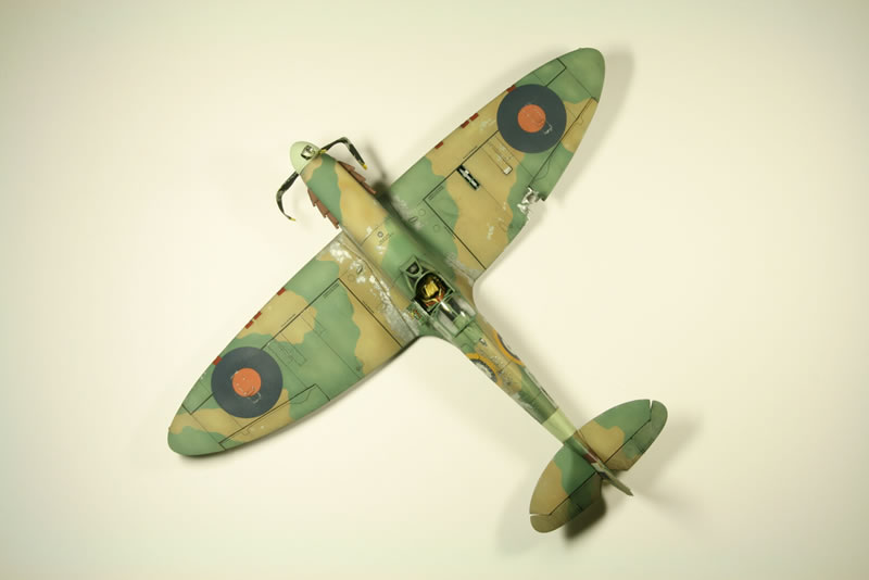
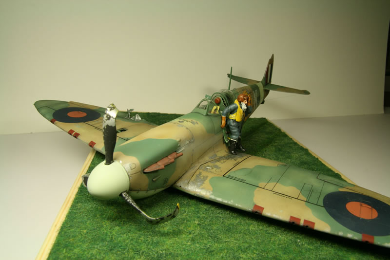
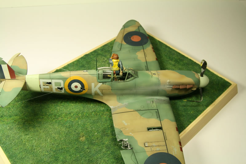
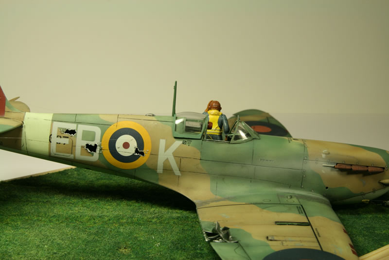
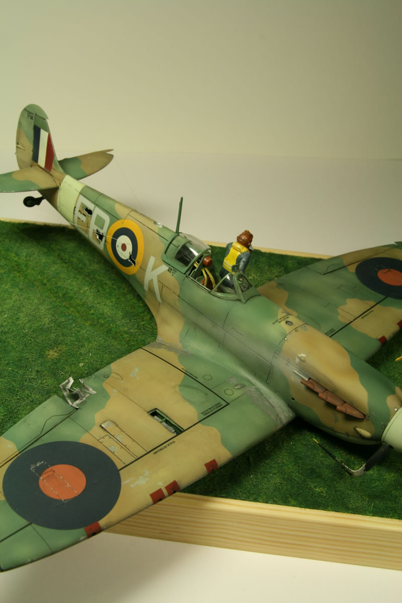
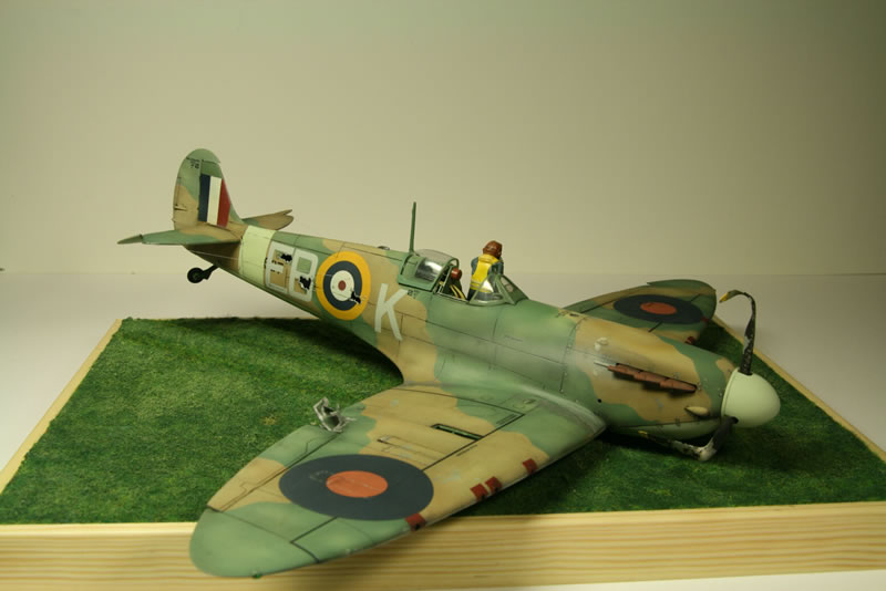
The Spitfire Mk. II was the first mark produced by the large, new Castle Bromwich factory. A few of these made it to the Battle of Britain in the summer of 1940. Barely a year later the Mk. II was obsolete, having been superseded by the cannon-armed Mk. V. Most surviving Mk. II’s were relegated to training duties, but a few slogged it out on active duty until they had all been replaced. I wanted my Hasegawa Spitfire II 1/32 kit to represent one of the last, a war-weary Spit that had been battle-damaged and belly-landed on return. The battle damage was copied from a number of reference photographs (albeit a combination of the damage to several different machines). The kit decals are supplied for two well-known aircraft. I made a mix of the two, creating a more anonymous 41 squadron Spitfire.
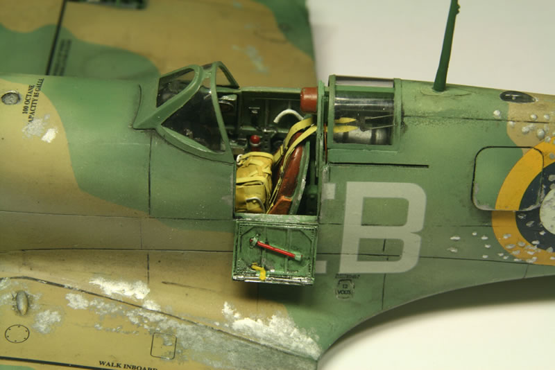
When I opened the box I realized two things. One was that the panel lines on the fuselage were raised – so I would have to rescribe those. And the other that the cockpit had that horrible floor that seems to be the bane of about half of the Spitfire kits. Apparently all the manufacturers are happily copying each other, including the dreadful mistakes. So I obtained a replacement for the cockpit from Aires (2061). Which had its own problems.
I started by rescribing the fuselage panel lines. In my previous attempt (a Seafire III) I made a bit of a hash of that as the new lines were too deep and harsh. Following advice found on the Internet I rescribed the lines the same way, but once done I dripped styrene glue along them and waited for that to dry. The glue makes the plastic swell and when the surface is then sanded flat, you end up with less harsh panel lines.
I also cut loose all control surfaces so I could set them away from the neutral position. The rudder cannot be turned very far because the Aires cockpit makes it impossible to change the rudder pedal positions accordingly (you can ‘misplace’ the pedals but not the bars on which they rest so you would get a misfit there).
Damage
The damage to the Spitfire II comprises:
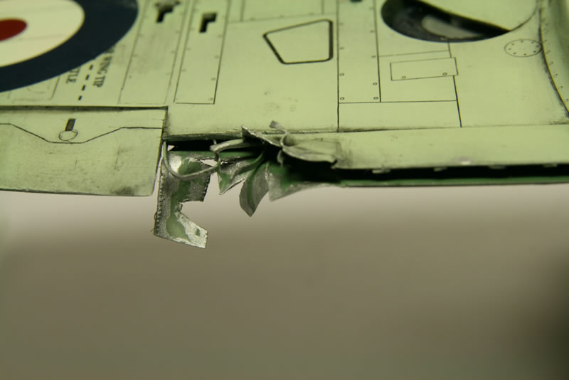
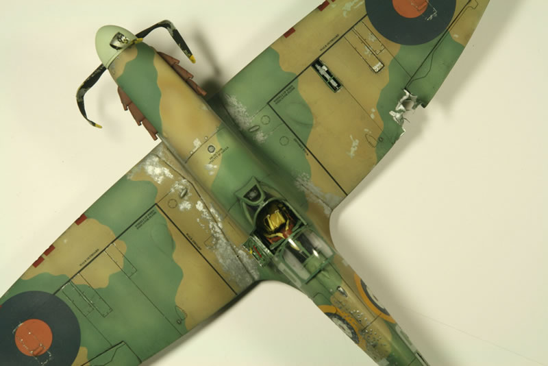
- One gun panel popped off altogether, exposing the gun bay, and the one next to it slightly loose.
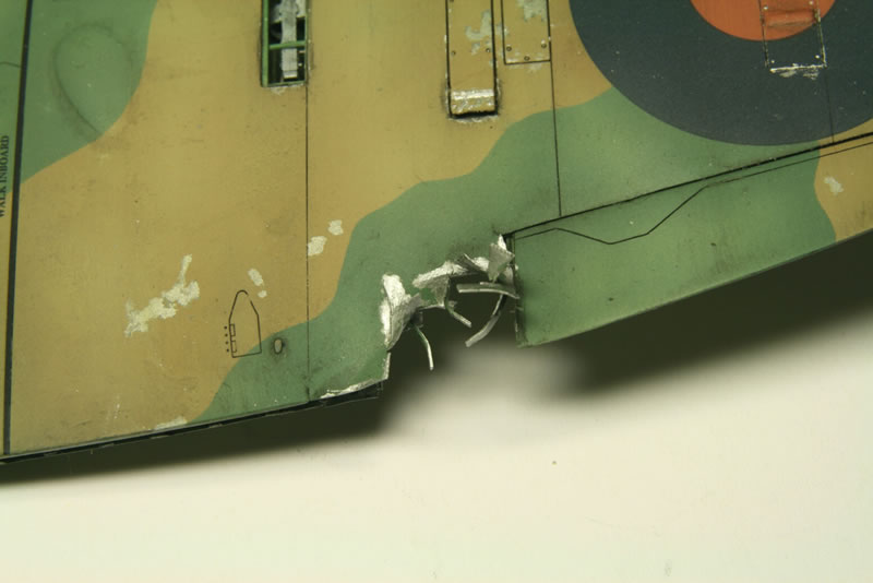
- Extensive damage to the trailing edge of the starboard wing and flap.
- Damage to the fuselage from exploded shells, with holes on the starboard side and a ‘peppered’ appearance on the port side. The original reference is the reverse but I wanted the ‘peppered’ effect to be visible on the side where the pilot is.
- Popped-loose panels, one along the upper back, the other the engine cover. The R/T transmitter access panel is also loose.
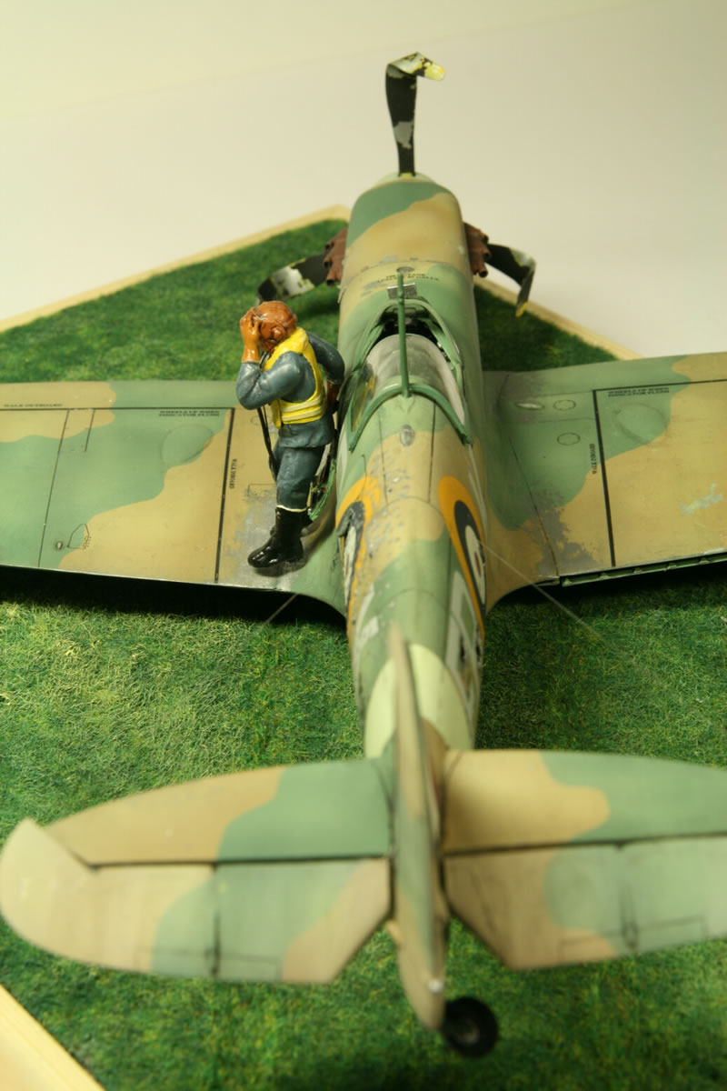
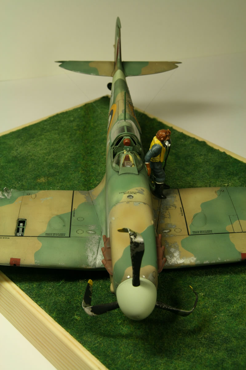
- Bent back propeller blades with extensive peeling of the paint.
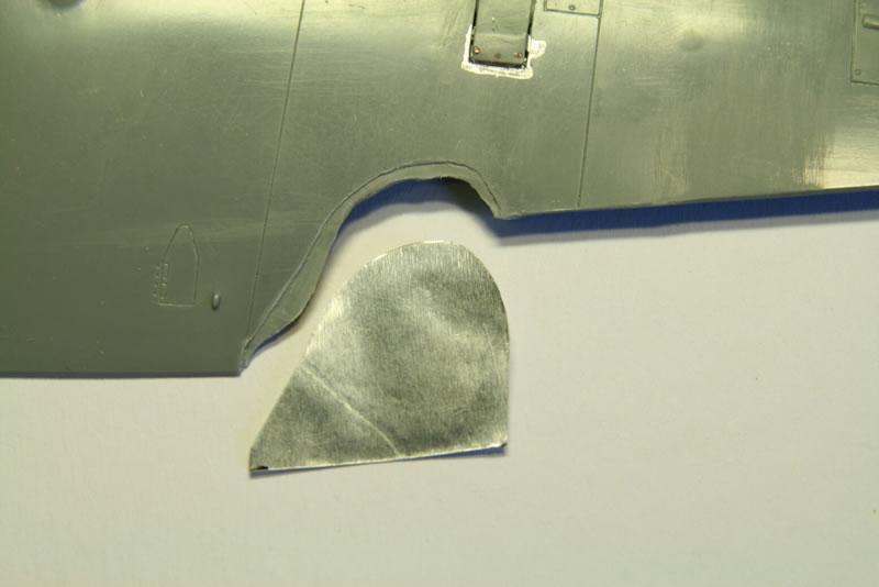
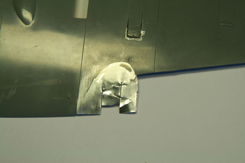
Lower Wing
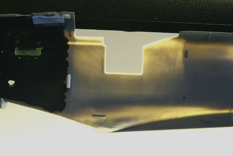
Quite a bit of modification was needed to the lower wing (photos 3 and 4). The wheels had to be up for the belly-landing. As supplied they are too thick to fit inside the wing. I had to leave off one half and even then the remaining half had to be modified quite a bit. I also had to thin the top of the wheel wells to create enough space for the wheels.
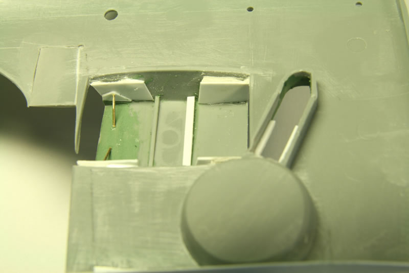
The main radiator structure is wrong so I rebuilt the sides and gave the radiator flap its bars. I reshaped the wheel wells and made supports for the wheel cover plates so they can easily be glued in place.
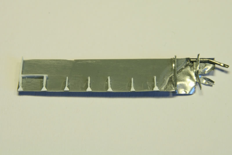
I built the one gun bay from scratch. Determining the structure presented a problem because all the reference pictures where internal wing structure is visible are from later Marks. There the gun bay was used for the cannon and the internal structure had to differ from that of the Spitfire II. I did the best I could, presuming that the vertical stiffener is located at the machine gun support (as it is for the no. 3 and 4 gun bays). The machine gun inside is from Vector, but I did not use its barrel (it broke off and is invisible anyway). I made two partial ammunition magazines by shaping a single one from styrene and then cutting it in two (since you have the front and backside next to each other, feeding the guns on either side). There is a lot of detail like the ejection chute, ammunition feed belt, pressured-air lines, etc., most of which is nearly invisible.
The rest of the machine guns are hidden except the tips of number 1, 3 and 4 guns. Those I made from styrene rod. Number 2 gun received its flash tube (drilled out styrene rod).
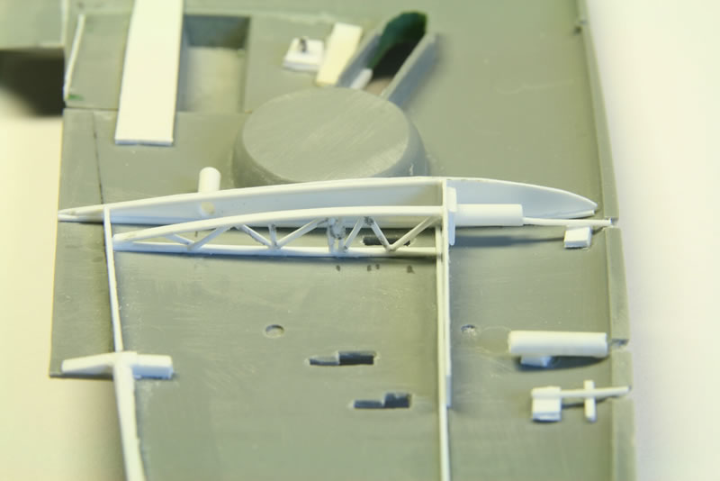
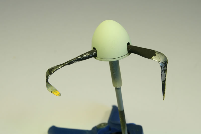
Propeller
To reduce the chance of messing up I experimented with one of the spare propeller blades coming with the kit (and it has a lot of those). I used a hairdryer at its hottest and that works quite well except that you have to use tools for the bending and holding, otherwise you end up burning your hands. I bent all three propeller blades into the required shape (taken from a couple of reference photographs). After that I mounted them on the spinner backplate.
The whole assembly was airbrushed ModelMaster Aluminium (photo 5). Parts of the propeller blades were coated with salt. The tips were sprayed yellow and the remainder black after masking off the tips (photo 6). I had a bit of a difficulty because the salt makes it hard to mask off the yellow properly. The Sky-colored spinner was painted separately.
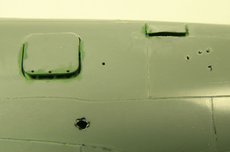
Preparing the Damage
I started off with the loose and open panels (photo 7). A very sharp needle was used to scratch along the panel lines, deepening them progressively. The advantage of the needle over cutting with a knife is twofold. The needle is slower so the chance of a mistake or slip is much less. And the needle doesn’t distort the plastic around the panel line. Once the line was deep enough I thinned the backside so the panels could be bent out, where needed. Behind the bent-out panels constructions were made from styrene to keep them in place.
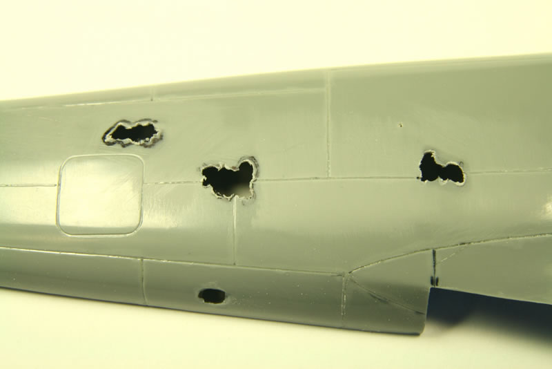
The big holes on the starboard side of the fuselage (photo 8) were made by thinning with a motor tool from the inside, making sure the thin rims bend outwards. On the port side a few small holes were made by pushing a hot pin through from the inside. Most of the damage on the port side consist of bulges in the skin where the paint has peeled off. Rather than try to push through I made them from superglue droplets (photo 9). I first tried styrene glue on a spare wingtip but that created plateaus instead of bulges. The superglue is better though it still spread too much for my liking and the resulting structure is much coarser than the reference. Maybe it would have worked better with a thicker superglue. The inside of the fuselage was painted matt black so nothing (of the lack of internal detail) is visible through the holes. A big piece was cut out from the trailing edge of the starboard wing (photos 10 and 11). The problem with doing this to a Mk. II is that the skin panel is very large, from the wing spar all the way to the edge (on a Mk. IX, which is the type in the reference picture, that panel is split into two). Rather than replace the whole panel with sheet metal (the only material that I can think of that can be bent into the required shape) I made a rounded cut-out with a ledge on which the sheet metal plate rests. The connection, with superglue, is rather flimsy and it did incur a bit of damage later on. The sheet metal was cut up a bit and with a sharp needle rows of holes were made, where the skin popped off the rivets. I kept the sheet metal itself flat for as long as possible, bending it into shape at a late stage.
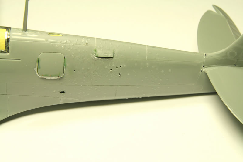
The starboard flap is hanging down a bit so I needed to make the internal structure there (photo 12). The end is blown off completely. The sheet metal at the tip was made the same way as that on the wing. Some internal structure had to be made for the wing as well.
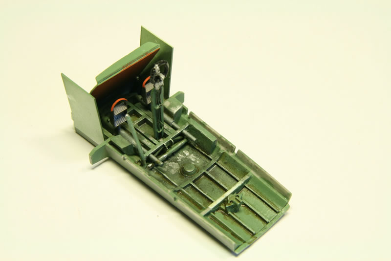
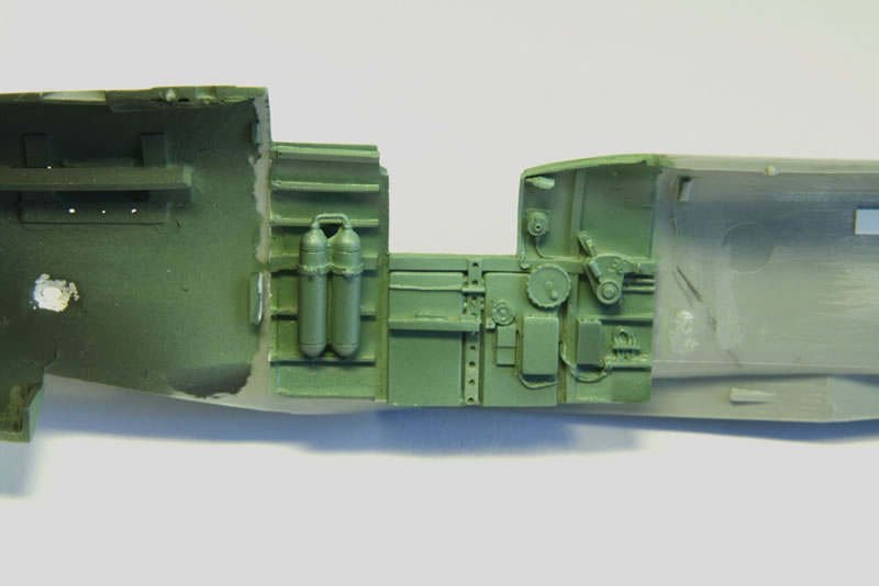
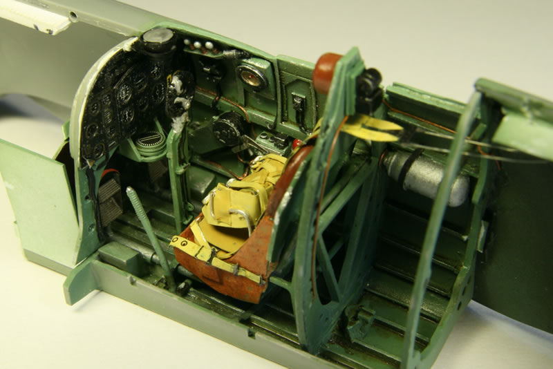
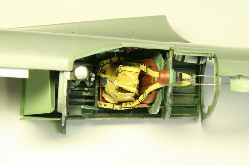
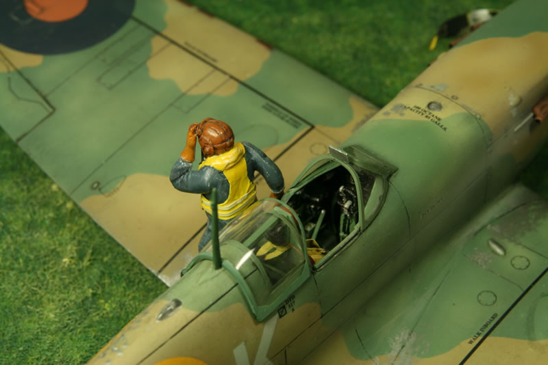
Cockpit
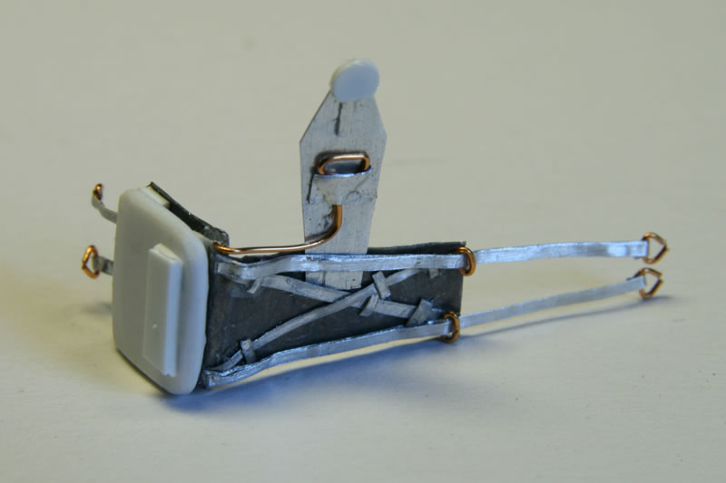
There were a few problems with the Aires cockpit. For one, it is a Mk. V cockpit so a few features had to be added (the remote contactor from the kit) or removed (the row of Very cartridges at the front of the seat). There are some errors as well. On the port side is what looks like the Sutton harness release, which should be on the starboard side. The biggest problem is the seat. I checked all my Spitfire kits in stock and in almost all cases the seats are too wide, often up to 20%, and the Aires seat is even wider than most. It is so wide that there actually is a problem fitting it inside, leaving virtually no room on either side between seat and sidewall. With a fine saw about two millimeters were removed from the center. The seat adjustment mechanism was taken from the kit and a lot of the seat support, including the armor plate, was scratchbuilt.
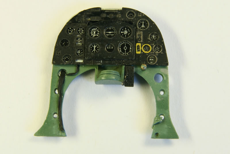
The cockpit frame with the seat support from Aires did not fit very well, so I used the kit part instead. The same applied to the gun sight. I fiddled for a long time trying to get the Aires sight in position, but in the end gave up and used the kit part.
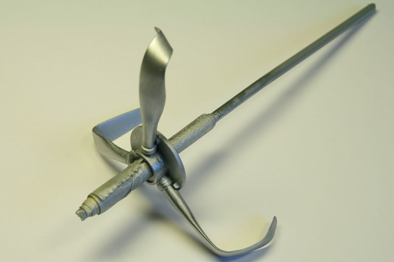
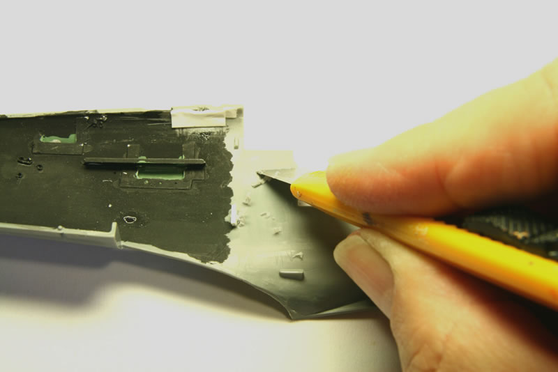
For installing the Aires cockpit the sidewalls of the fuselage as well as the Aires sidewalls needed to be thinned. This was done by ‘shaving’ with the backside of a knife (photo 13). The shaving gives a much more controlled result than either sanding or using a motor tool. The progress can be inspected by holding the part up to the light (photo 14). The uniform thinning is easy to see (the swirls are structures inside the plastic). The most important area is the top rim. If too much material is left there, the rim becomes unrealistically thick.
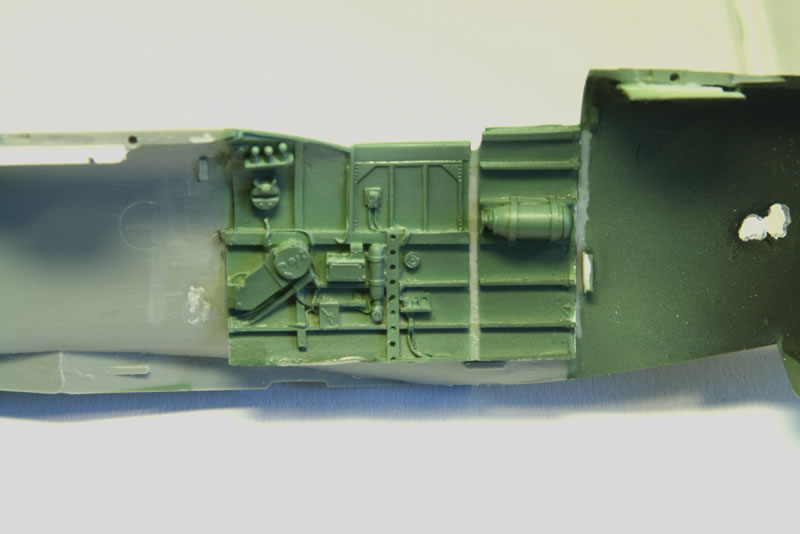
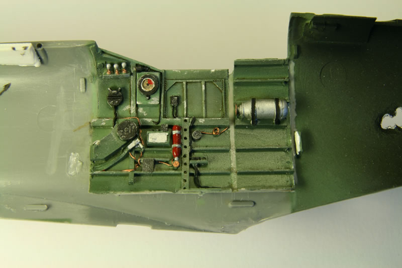
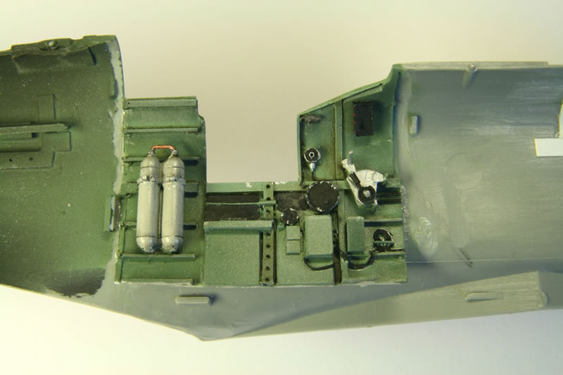
As supplied the Aires cockpit floor doesn’t have any structure in front (that is, towards the Spitfire nose) of the instrument panel. Sides as well as the firewall between the fuel tank and the cockpit were made from sheet styrene. The result is shown in photos 15 through 20.
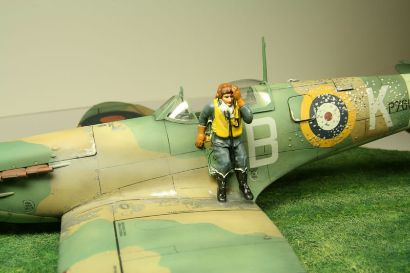
Pilot Figure
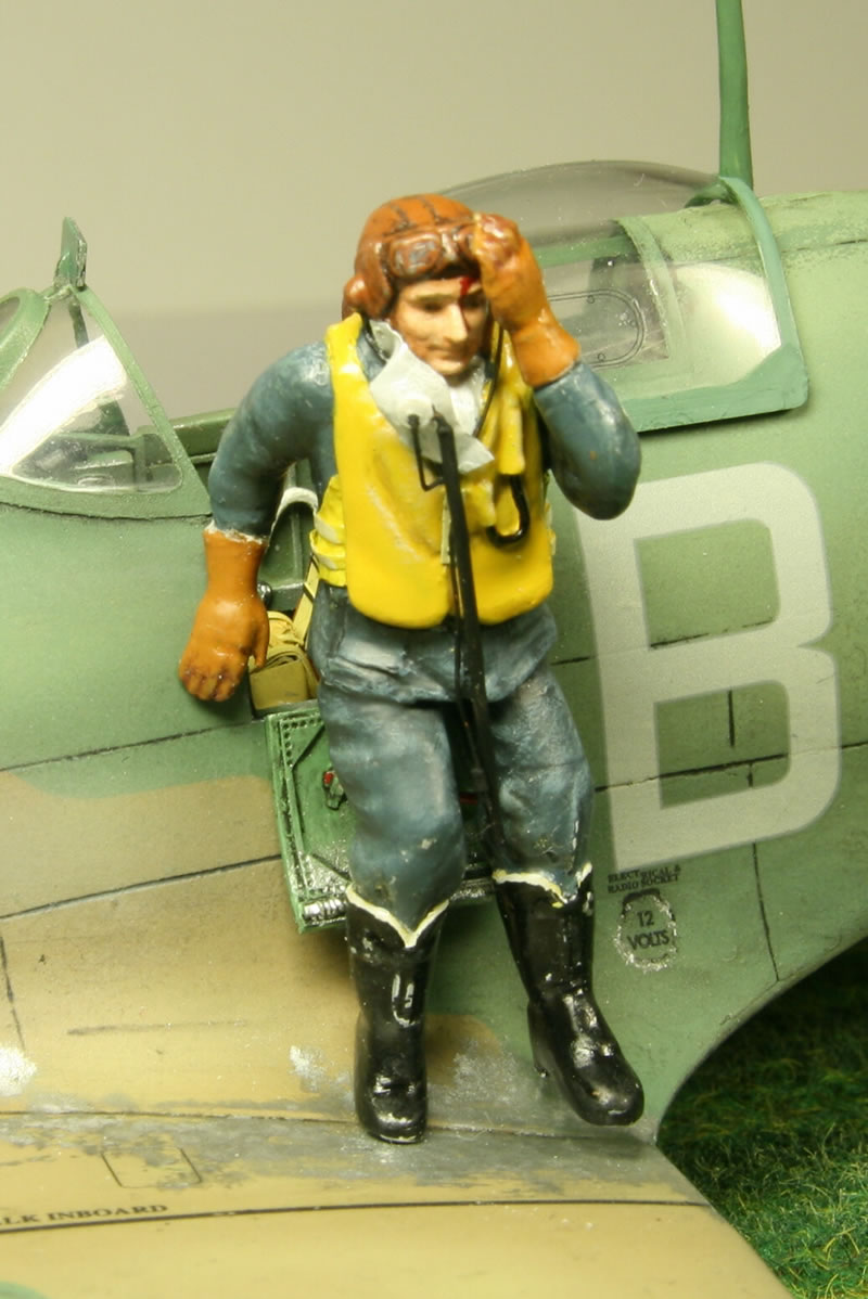
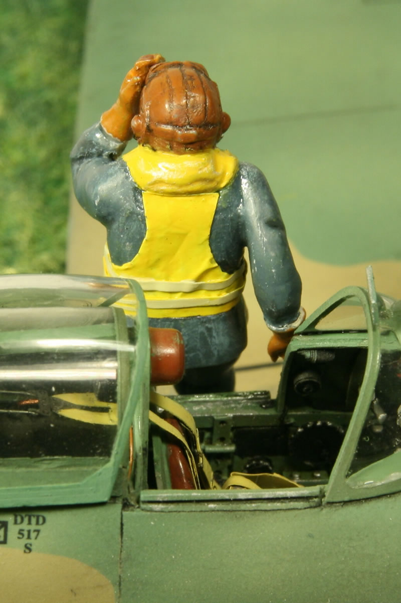
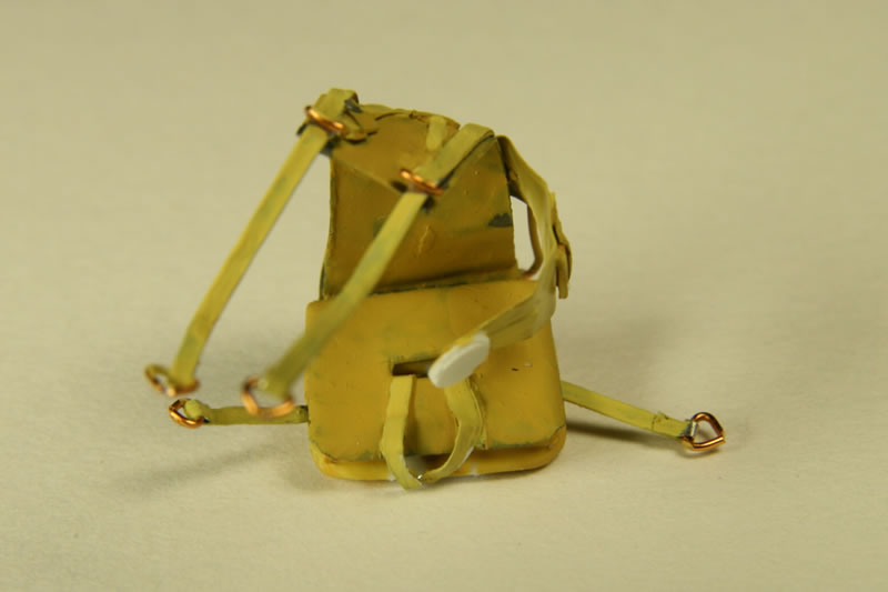
The pilot (photos 25 and 26) had to be modified extensively, from being seated to having just left the cockpit. That meant a lot of surgery (plastic surgery, as it were). The parachute was removed (including the harness on the front side). I made a parachute pack from scratch and left that on the seat in a collapsed state (photos 21 through 24). Knees and elbows of the figure were adjusted. He lost one foot. And so did I (his) and had to replace it with one made from styrene. The legs were also cut off the body and re-adjusted. The hands underwent the same fate. The fingers were broken to allow them to go from bent to almost straight.
The outline of the life vest was scratched with a sharp needle to make it stand out from the chest. The uniform jacket below the life vest was also given some details like pockets. Some surface items (the blow pipe and its covers, and a tying strip) were made from metal wire and sheet metal. Quite late I realized that the life vest as I had it (front and only the collar at the back) made no sense, there had to be some kind of structure at the back. With Internet to the rescue I found out that that is indeed the case. The back was made from aluminum foil (a bit thicker than the kitchen variety) with sheet-metal strips.
The oxygen mask and oxygen line plus the wires for headphones and microphone were made from sheet metal, a styrene disk and metal wires.
Painting
The painting (photos 29 through 36) turned out to be a real pain. It is a good thing that I decided to interlayer the (mostly Humbrol enamel) coats with Future (thinned 50:50 with alcohol and applied with a brush; that gives a very smooth finish, better than I can airbrush it on). That way I could use white spirit to remove some of the undesirable effects that I managed to produce along the way.
One misfortune I should also mention. I had drilled out along part of the length of the antenna mast, inserted a piece of a needle in there, and made a support structure for the base inside the fuselage. Unfortunately I decided to let the needle stick out far inside the fuselage, so I had to paint it matt black, otherwise it would be visible. Which meant putting the antenna on before closing the fuselage. I reasoned that I would just have to be careful. And I was. Each time I put the Spitfire upside down I took care to give it support. And then it was in front of me, I reached for a pair of tweezers, hit the antenna with my hand, and ‘ping…’, off went the top part. You can see its demise between the Dark Earth coat and the Dark Green one (photos 28 and 29). Later I drilled a hole on either side of the break, inserted another piece of stiff wire (the needle is too thick for that part) and filled up the gaps with superglue. All in all, I managed to undo the damage. And vowed never again to do something dumb like that. The needle is a good idea as it makes the positioning of the antenna easy, but you simply don’t put on fragile details till the end.
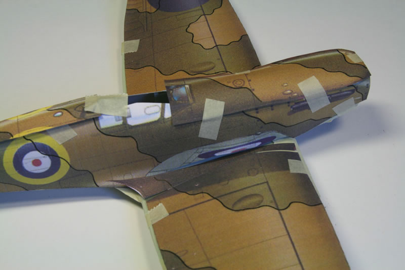
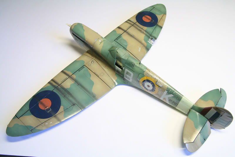
The first part in the painting was making masks for the camouflage pattern on top (photo 27). I decided for the less usual ‘B’ scheme, which is the mirror image of the ‘A’ scheme that became the later standard. ‘B’ schemes were generally applied to odd serial-number machines - though not universally so, one notable exception being EB-Z P7666, one of the Spitfires represented by the kit. The problem with the camouflage scheme is that you cannot simply make it from the reference pictures, views from top and left/right. For one thing there is the problem of foreshortening where the pictures ‘see’ the aircraft at an angle. But there tends to be a real problem in that the reference picture views often do not sync. The wing roots are notoriously problematic. I scanned the reference pictures and printed them at the correct scale. I then used another 1/32 kit (a Seafire I, but you could also use the kit itself) and stuck the printed pictures on there. On top of that I put pieces of cellophane (from the bags that some kits have their sprues in) and on those with a marker pen drew the outline of the masks, adjusting the mismatched regions as well as possible. A prominent mismatch is the top engine cover. The top view clearly has the lowermost tip in green, but the side view has the whole part there brown.
The squadron codes are a perennial problem as there was no true standard at the time. And for some reason 41 squadron is well-represented with pictures showing the port side of their aircraft (where the sequence is the fairly standard EB-O-letter where O stands for the roundel and letter the individual aircraft, K in my case). But starboard views are difficult to find so did they use also EB-O-letter or letter O-EB? I found one picture showing EB-O-K and EB-O-N so I stuck to that sequence.
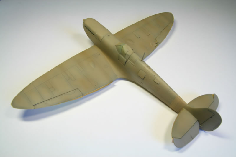
The serial number (of which very little is visible as the Sky band as well as the squadron codes are painted over it - a common practice in those days) was re-organized so a 7 becomes the last digit (changing the number from P7666 to P7667). I first applied black preshading. It came out rather heavy as I had difficulty with my airbrush but at this stage that wasn’t much of a problem. After airbrushing the lower surfaces a pale Sky, I created the Sky theater band near the tail a darker Sky (it would have been put in place much later than the painting of the Spitfire so it would not have faded as much). The first top-surface coat was the Dark Earth color. Though in this case, the weathering was going to be rather extreme so I mixed in quite a bit of white. I also varied the amount applied to make it heterogeneous (photo 28).
So far, so good. I put on the masks (generally outlines cut from masking tape with larger areas covered by yellow pads) and applied the green. This was also made non-uniform. The first disaster struck when I removed the masks. In places the Dark Earth came off. Some of it I could convert to bare metal (damage) but in other places I had to respray the Dark Earth. Next came the weathering. I followed advice from the Internet (David Rapasi) and tried spraying on irregular patches of a mix of clear (I used gloss instead of dullcote but that shouldn’t matter) and white. The problem is the white. It works very well on the blues of the American Navy aircraft, but it creates weirdly pale effects on the RAF colors. You cannot use white alone on brown because brown contains too much red. White plus red gives pink, while you want a more orange shade for faded red. So you have to use yellow. In the end I used a 50:50 mix of white and yellow and that seems to work well.
I applied a coat of Future and the decals. The red centers of the wing top roundels are way too dark. But I couldn’t figure out how to lighten those with yellow-white without making the adjacent blue into green. Fortunately I found in my spare parts box roundels of the correct size with a much better red. So I cut out the red circles and applied them on top of the roundels. Perfect!
So now for the finishing touches. Fine washes on panel lines no problem. And then the smoke of the machine guns and the exhausts. No matter what, I found I could not control the fine nozzle of my airbrush. It seemed to have only two settings, ‘off’ and ‘too much’ with nothing in between. By the time I had a reasonably uniform streak, it was always way, way overdone (photos 29 and 30). I probably tried three or four times, each time wiping off the undesirable result. I found I couldn’t do it. In the end I settled for grey exhaust stains and no gun smoke stains. Perhaps that is more realistic anyway, as I have yet to see a reference picture with noticeable smoke stains. Exhaust yes, gun no.
After that it was time to make the damaged areas on the wing roots, etc (photos 31 through 33). That was done by painting on aluminium and silver in patches. Not quite dry-brushing but jabbing the brush onto the surface instead of making strokes. Except for the fact that the enamel dried too much on the brush and I had to sand off some of the excess, I am quite pleased with the result.
A dullcote was sprayed as a final finish. The one gun panel that was going to be open was removed (it had been put in place temporarily during the painting). The damage to the wing was bent out.
Finishing Touches
The diorama base was made by covering a piece of particle board with garden dirt mixed with Elmer’s white glue. Three grooves mark the trails made by the underside of the Spitfire (air inlet and radiator housings). Over that came static grass, with the grass in the grooves flattened.
The pilot was mounted on the wing and the Spitfire screwed in place (there is a screw through a hole in the bottom of the air inlet, otherwise the Spit doesn’t lean on its nose). The IFF aerials from the fuselage sides to the tips of the horizontal stabilizers were made from fishing line, painted silver. On the side of the fuselage I tied thick knots in the line, pushed the end – with knot – inside and plugged up the remaining hole with styrene rod. On the other side I drilled holes through the stabilizers from front to back and the line goes through (this job was done very early on, while the stabilizers were still separate). I used superglue to fix the line in the hole. The line actually comes out a bit and is glued further on as well. Because it is transparent there, you don’t see it.
There is no aerial for the main antenna. Spitfire IIs don’t seem to have that (all the color profiles for Spitfire I’s show the aerial but it is conspicuously absent on all Mk. IIs).
This kit was quite fun to build, but at times very frustrating as well.
References
- Humphreys R (2000) The Supermarine Spitfire. Part 1: Merlin powered. Modelers Datafile 3 (B camouflage pattern)
- Price A (1977) Spitfire. A documentary history (pp. 68-69, bent propeller blades)
- Price A (1996) Spitfire Mark I/II Aces 1939-41. Osprey (pilot figure details and aerials)
- Price A (1997) Wings of fame, vol. 9 (starboard view of 41 squadron Spitfires)
- Price A (2003) Spitfire in combat (p. 163, damaged Spitfire)
- Hoffmann J, Matusiak W (2000) Supermarine Spitfire IX-XVI, Modelmania 5 (wing damage, picture 108)
- Rapasi D (2010) Weathering with “dullcote”. Aircraft Resource Center
© Max Otten 2013
This article was published on Tuesday, December 31 2013; Last modified on Thursday, January 04 2018