
Rebuilding the 21st Century Toys 1:18 F-104G Starfighter - Part 2
By Dr Menelaos Skourtopoulos
Ejection seat and canopy
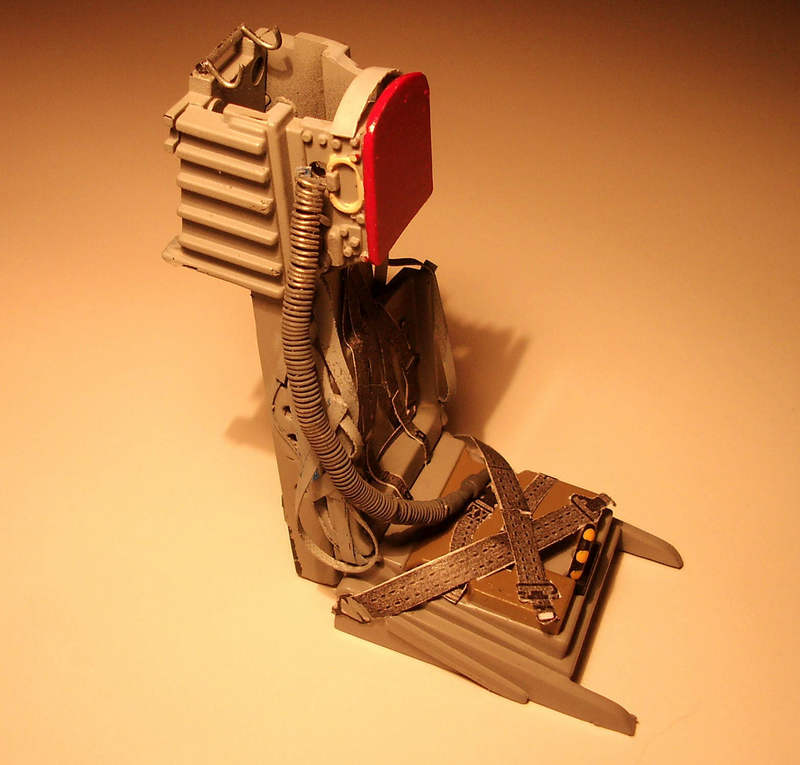
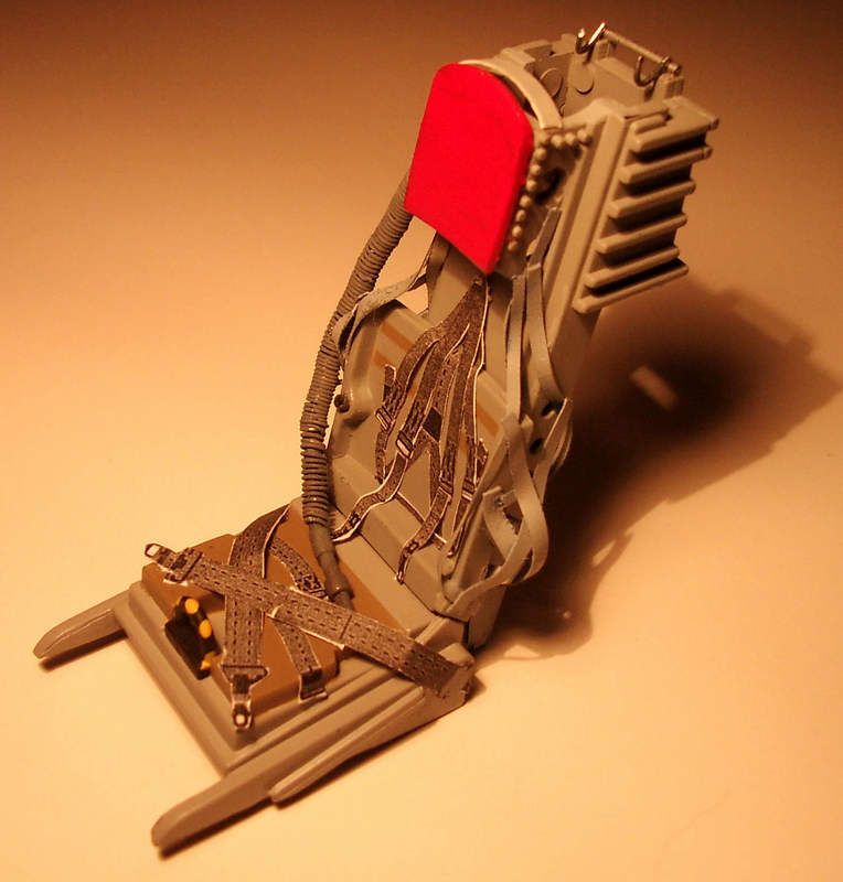
Inside the kit there’s a good replica of the Lockheed C2 seat that replaced the dangerous downward firing C1 seat. After many accidents that cost many pilots life the installation of the upward firing C2 seat was a very welcome event. The HAF used the C2 seat until 1973. From that year on the much better MB Q7 seat with zero zero capability replaced the C2 seat and the accident rate was fallen much lower.
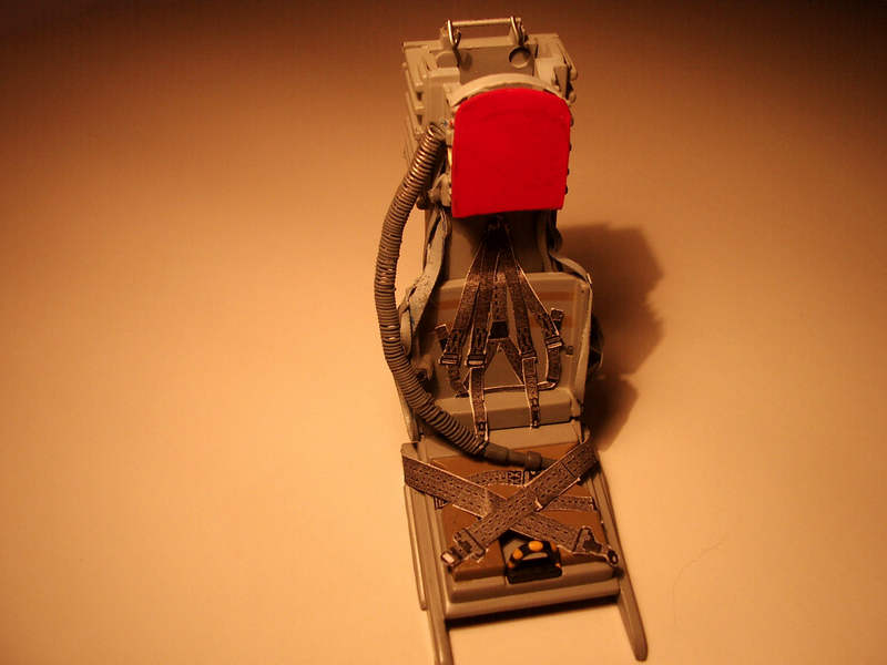
I didn’t want much more scratch building so I decided to use the C2 seat from the Kit. I wanted to depict an early HAF Starfighter so I upgrade the C2 sear with seats belts a new head rest, new oxygen tube and some canopy frame hooks. The seat belts came from Eduard’s set for the F-104 in 1:32 scale. I just enlarged them by copying the whole set up to the 1:18 scale.
I also build the pilot’s legs retraction belts (not shown).
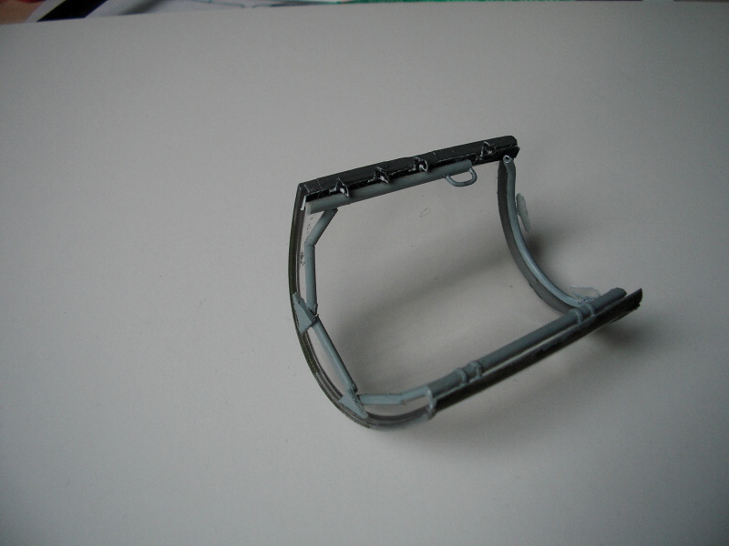
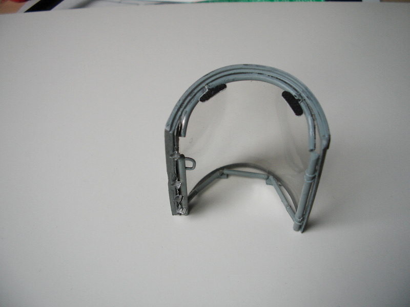
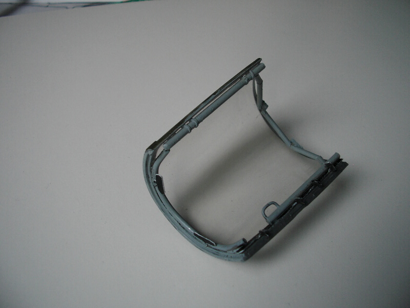
The movable part of the canopy is just a naked piece of plastic and the whole frame inside it, had to be made from scratch. I used some solid plastic styrene, wire and some detail photos of that region.
Some general works outside the cockpit…
After all work was done in the cockpit (see Part 1) and before the two fuselage halves closed, I had to do some working on the main gear bay.
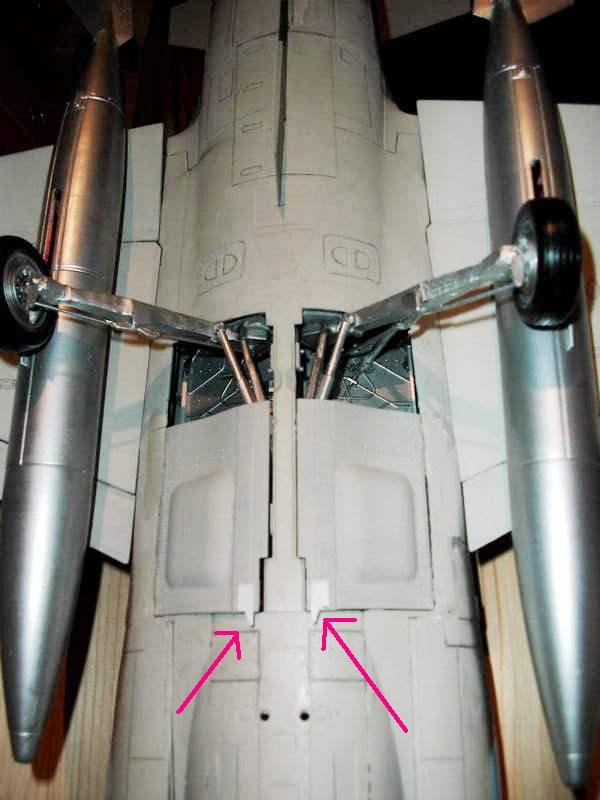
First I removed all the mechanism that holding the gear legs of the Kit, so that they could retract. The gear legs have to be fixed in a different angle and that means a lot of work. Considering the enormous weight of the kit, the “new” gear legs should be fixed carefully and have to be strong enough to withstand that weight.
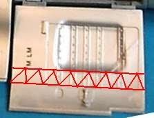
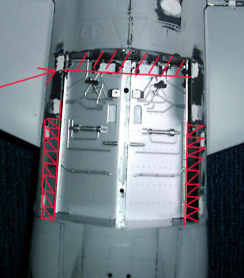
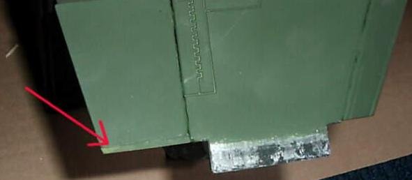
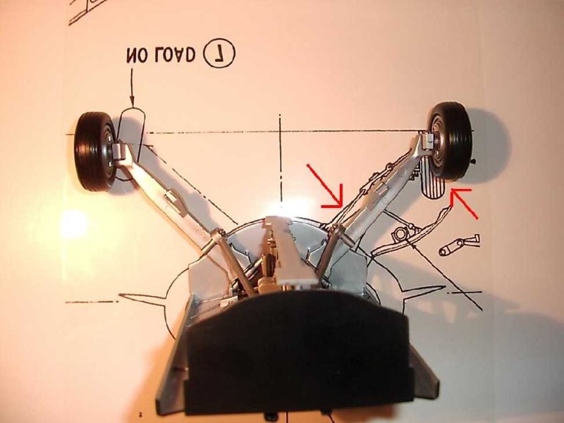
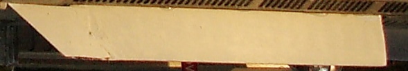
After a long study of the F-104 plans I had, I noticed, that the opening of the Kit’s landing gear bay is much larger than the real one is. But this problem was solved easily, because the gear doors are simply larger. So the only thing to do is to cut that part out of the gear doors, and glue it on the fuselage (the red regions in the picture).
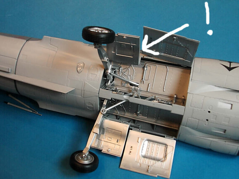
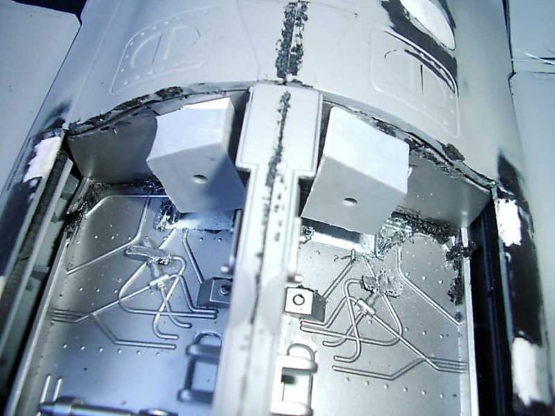
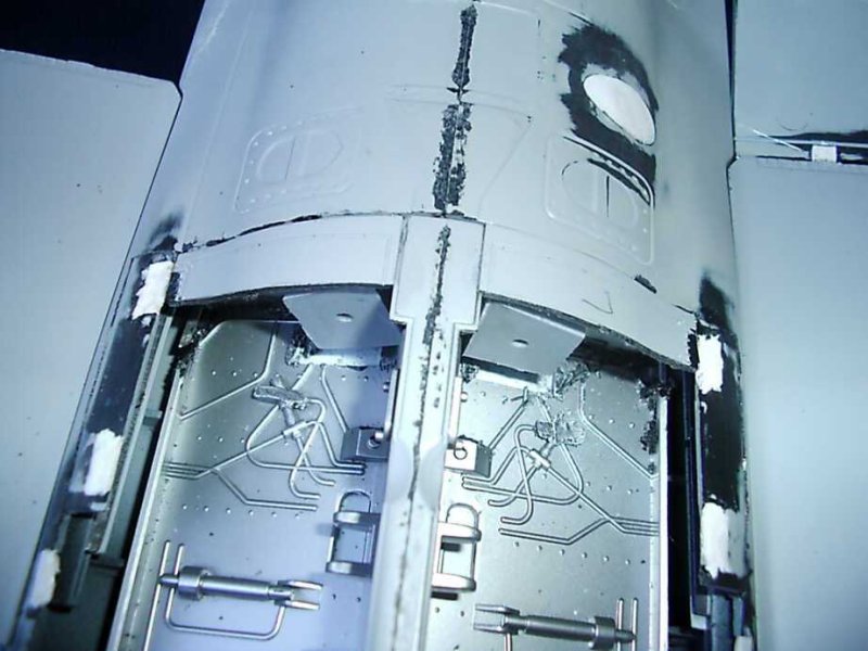
I used two big resin pieces to attach the landing gear legs. I fixed them with epoxy glue to withstand the models weight. On that two resin pieces the two legs had to be fixed. I drilled two holes on them and equal plastic pieces were fixed on the gear legs to pass into those two holes.
The details on the fuselage, as I wrote before are more than enough, but here and there I had to do some corrections. The panel lines are generally too deep but I let accept them this first time (in my future project TF-104G I will fill some of them with putty).
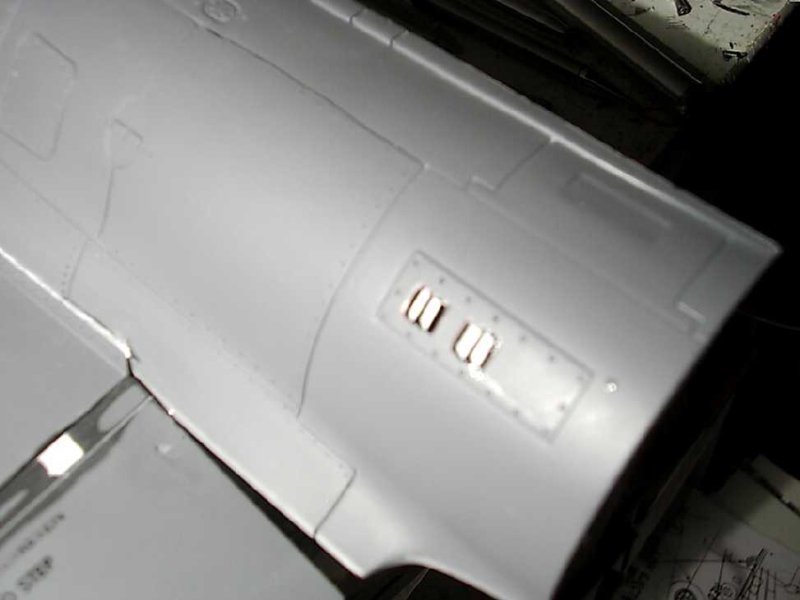
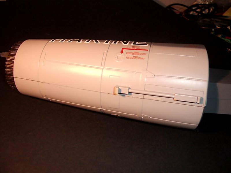
The engine vents in the back left side are not the best ones. I drill two big holes and represented the vents with 4 small plastic styrene pieces.
The holes for the refuelling probe and the screws that connect the fuselage halves were covered with putty.

The slats, flaps and rudder are separate pieces, but have some awful openings on them and they have to be closed with putty. The same work was done for the landing gear doors.
I had to take some care for the radome, because there are some big lines from the moulds on it.
There’s also a big gap between tip tank and wing. This was closed with plastic sheet.
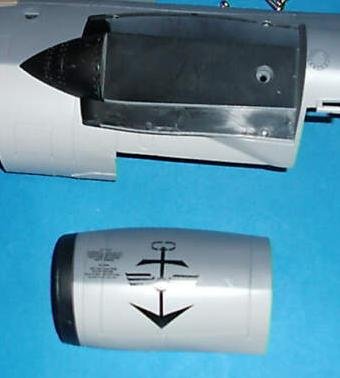
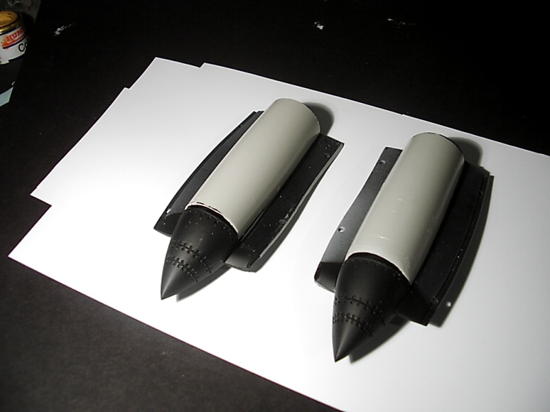
The intake cones are ok but there’s no detailing behind them. So I used some old fuel tanks from the spare box to represent the aerodynamic shape that goes inside the intakes.
The access hatch on each side of the air intake is not there and had to be engraved.
The arresting hook that comes with the kit is wrong and I had to modify it. I cut it off and modified its shape with my Dremel (photo not shown).
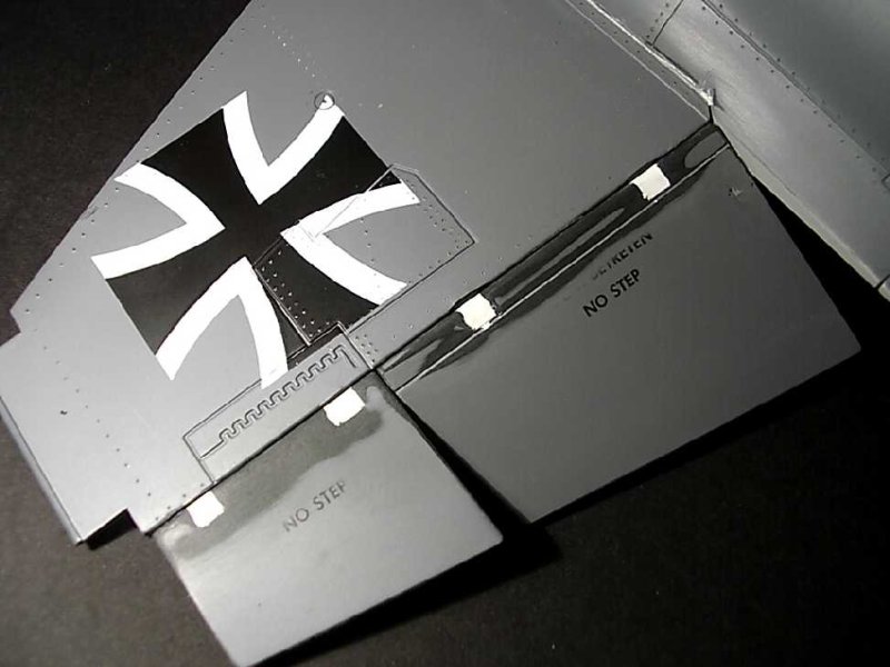
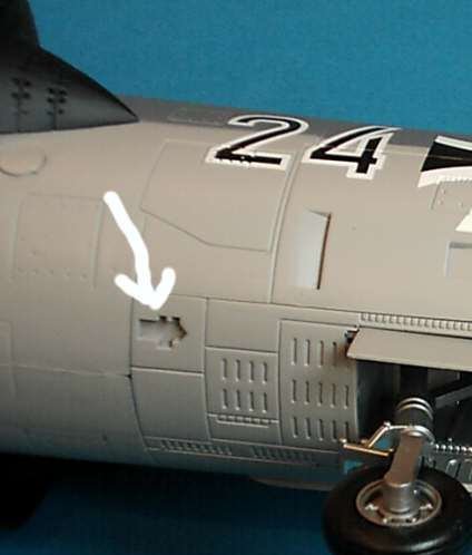
The ejector link mechanism for the empty canon shells had to be made also from scratch. There’s only the opening there and the rest was made from plastic sheet.
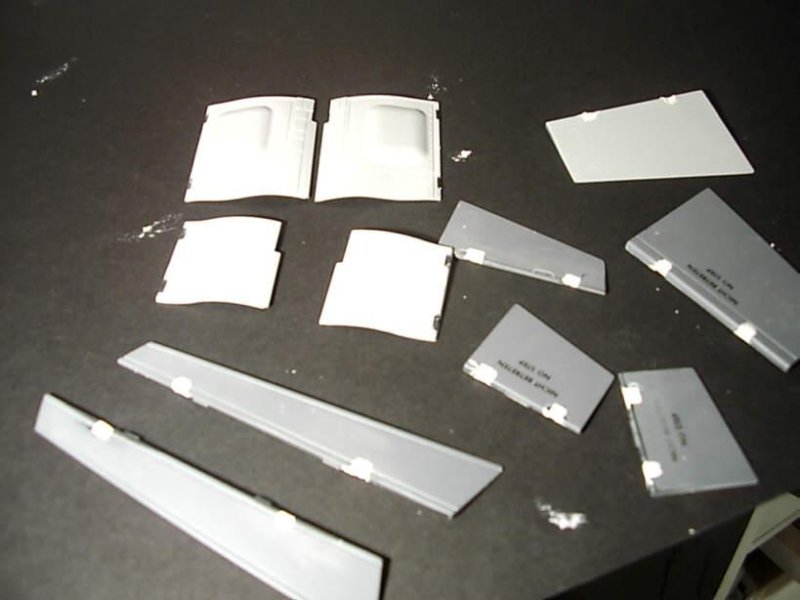
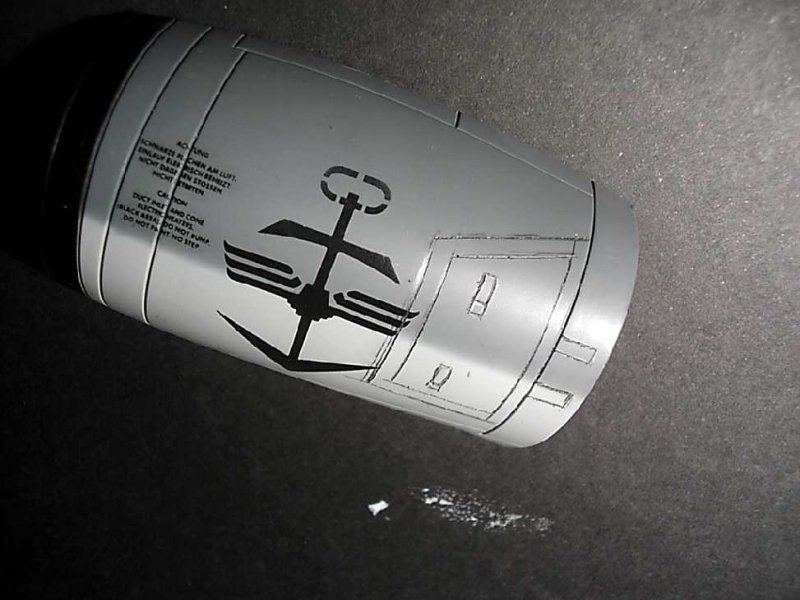
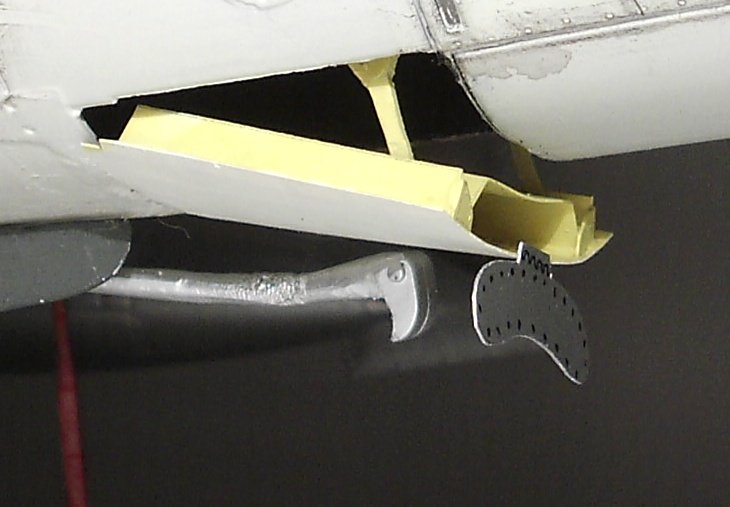
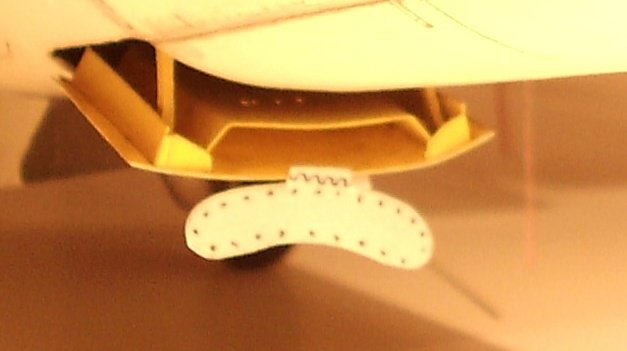
I also open the bay of the parachute brake to show it in the open position. The whole thing had to be made then from scratch using plastic styrene and some detail photos of the real thing.
The parachute housing door was separated and made again from scratch. I used again some good detail photos to represent it properly. You can also see at the photo the new shape of the arresting hook.
Landing Gear
The landing gear situation is unfortunately not the best one in this Kit. The nose landing gear is ok but needs some more details (Landing light, and retraction arm).
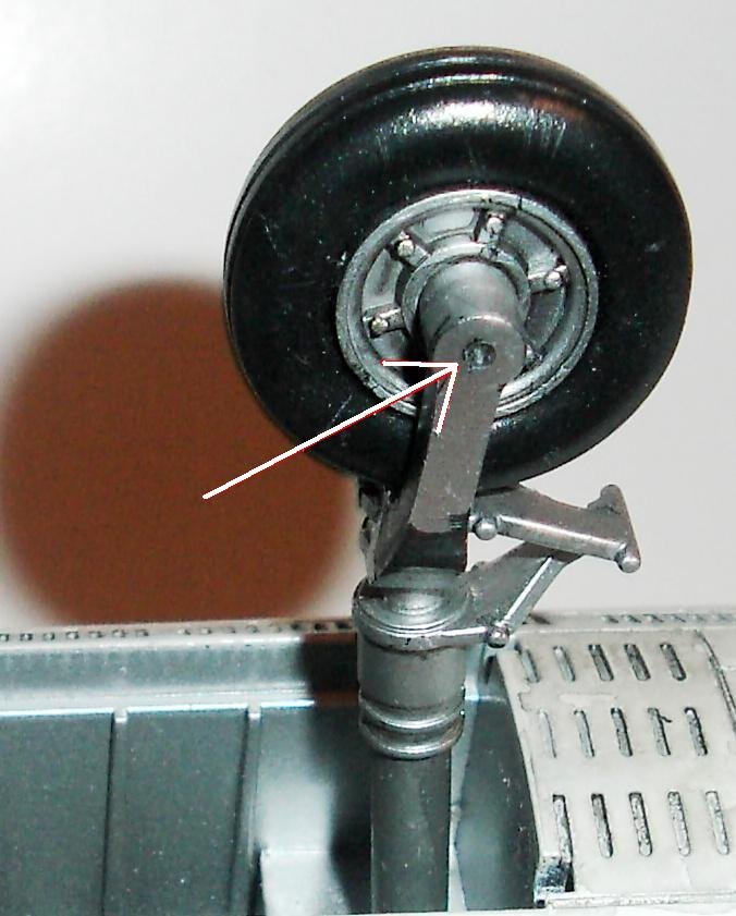
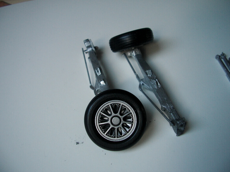
The big problem is the main landing gear that looks too simple and is practically almost wrong. The only high light is the detail level of the wheels that are really very nice made. Major work was to reshape to main legs. These are strong enough even if they are much more thin. I used again my Dremel for this.
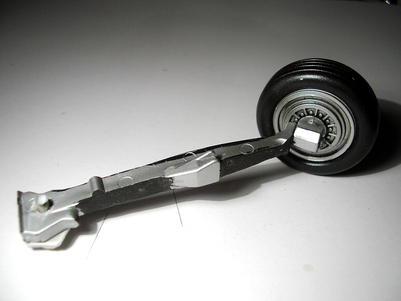
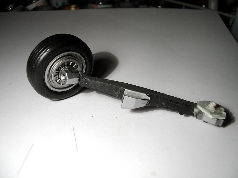
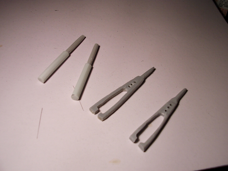
There’s only a retraction arm in the kit and you have to throw it away because it’s wrong. The landing gear retraction arms, had to be made from scratch. I used the equal pieces of the 1:32 scale Hasegawa Kit as templates and copied them up to 1:18 scale. The new parts were made from solid plastic, metal or resin pieces. The landing lights were made from clear plastic from the spare box.
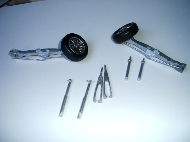
The landing gear struts were fixed in their position with superglue. Their geometry (angle) was the most difficult part of that action. I also make some additions on the main gear doors from small pieces of plastic styrene.
In Part 3 we’re going to see the big Starfighter painted and ready for take off!
© Menelaos Skourtopoulos 2008
This article was published on Wednesday, July 20 2011; Last modified on Saturday, May 14 2016