
Revell 1/32 Mirage IIIO
By Mike Prince
Introduction
The Dassault Mirage III served as the RAAF frontline fighter from early 1964, with the last disappearing from squadron service in June 1988. This included one hundred of the IIIO single seaters (“O” for “Oz”) and sixteen IIID two seaters. The bulk of the Mirages served in four operational squadrons, plus the Operational Conversion Unit, throughout their service lives. However, in the last two years, a fifth squadron was added to this list as the four main fighter squadrons and OCU transitioned to the F/A18 Hornet. This was 79 Squadron, based at Butterworth in Malaysia.
Throughout the aircraft’s service life Mirages wore a number of different schemes. They included:
- a polished natural metal finish with red or yellow trim around the intakes and a variety of colourful squadron flashes on the fin
- a painted silver finish with similar fin flashes but fewer wearing the coloured trim around the intakes
- several versions of dark green and grey camouflage, the earlier ones being wrap-around schemes and the last having light grey undersides, and finally
- a variety of experimental and service schemes using various shades of grey in the lead up to the transition to Hornets
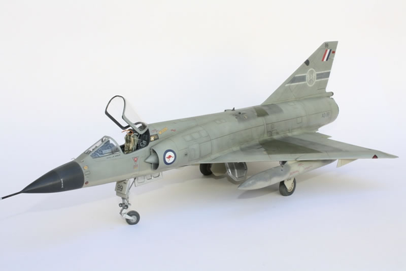
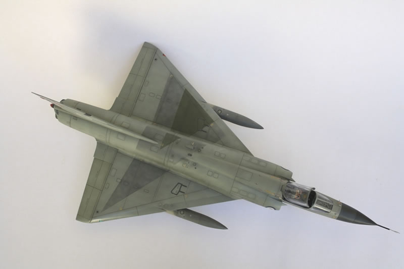
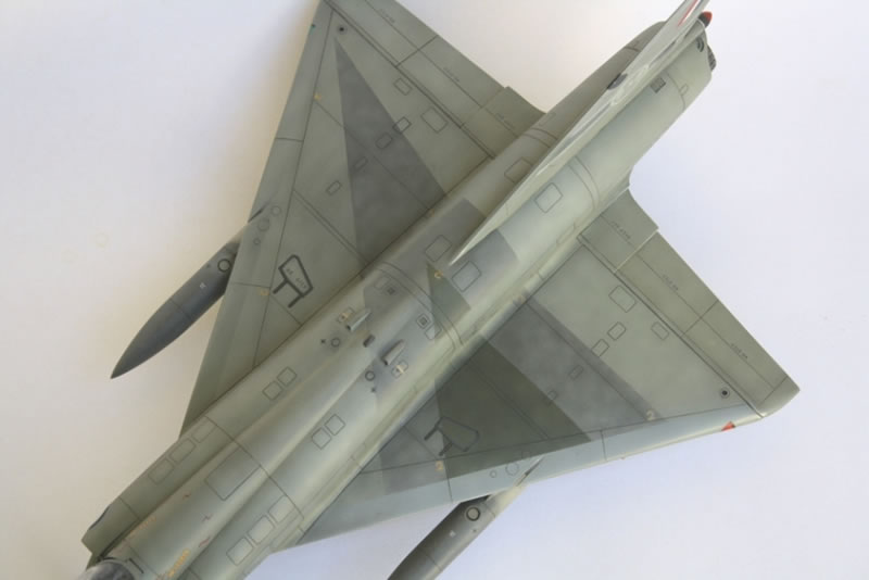
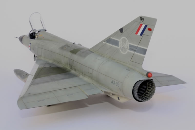
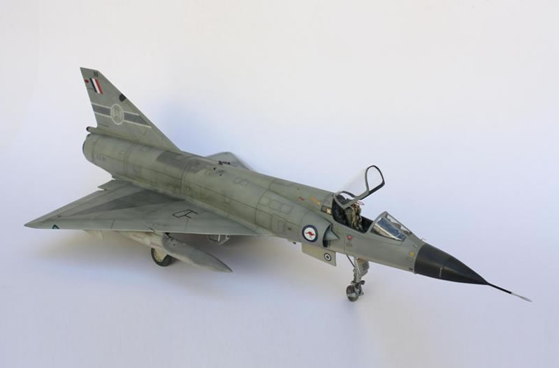
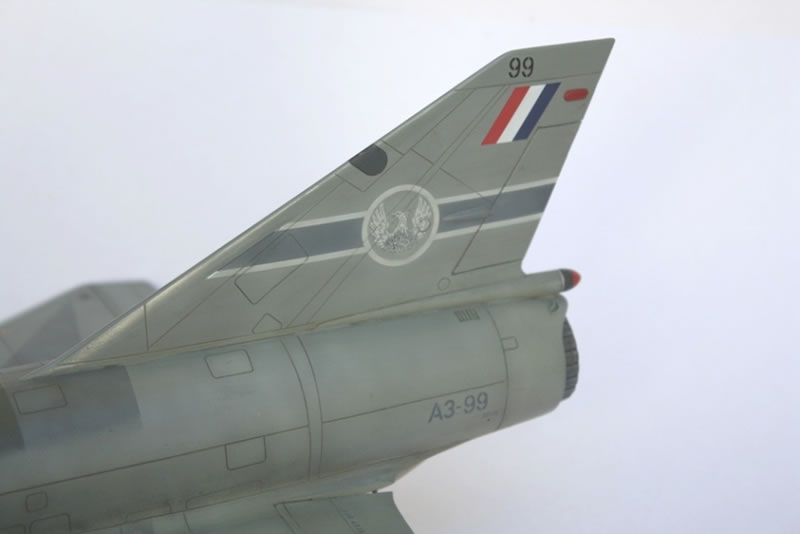
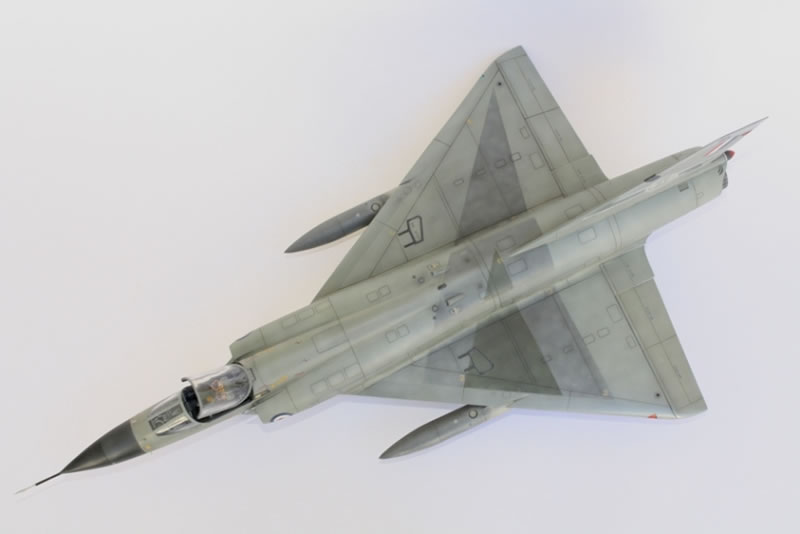
Of these, some of the most interesting were the experimental grey schemes designed not only to make the aircraft harder to spot in the misty skies over Malaysia, but at close range, also intended to disorientate opposing pilots during air combat manoeuvring (dog fighting). During the two years 79 Squadron operated Mirages they produced three of these disorientating schemes, each based upon an asymmetric triangle stretching across the aircraft. Two used a soft edged wavy triangle, one predominantly dark green on A3-19 and the other dark grey on A3-54. However, A3-99 was unique in that the triangle was hard edged, used both dark green and dark grey, and, unlike the other two, did not extend down the fuselage sides. It was reportedly very effective. It also makes for an interesting model.
The Kit
The Revell kit dates from the 1970s, with all that this implies. The overall shape is good with a simple parts breakdown, but much of the detail, such as louvres and vents, is soft or simply non-existent. Panel lines are a combination of raised and engraved lines, though fairly accurately done. The main wheel wells are shallow blank canvasses waiting for attention, while the nose wheel well is just a hole. Finally, the cockpit is excessively simple – but this is where things have changed with the relatively recent release of a magnificent resin cockpit set from Fisher Model and Pattern. This even comes with the option of early and late versions of the ejection seat, the Mk4 seat having a soft parachute pack forming the upper part of the seat, and the Mk6 having a hard case.
So what does building this kit entail? In simple terms, it involves a resin cockpit, new wheel wells, a new exhaust, numerous detail improvements and engraving all the panel lines. While this all took a little time, none of the steps was overly complex and the results were well worth the effort.
The Improvements
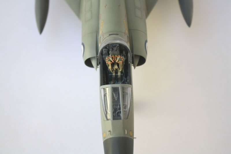
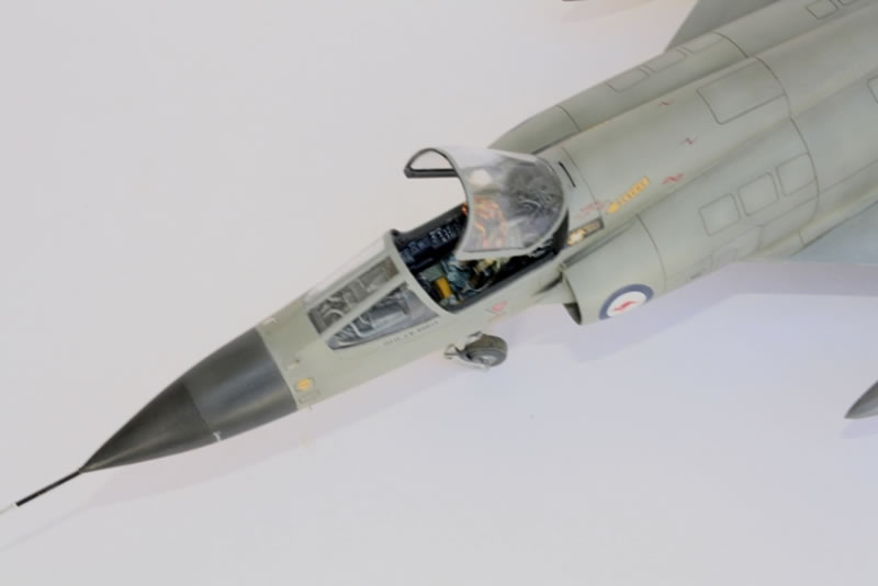
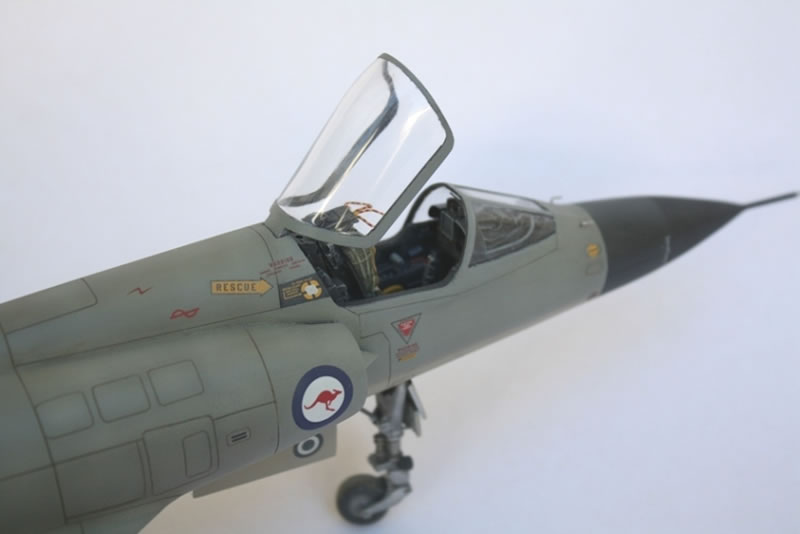
Cockpit
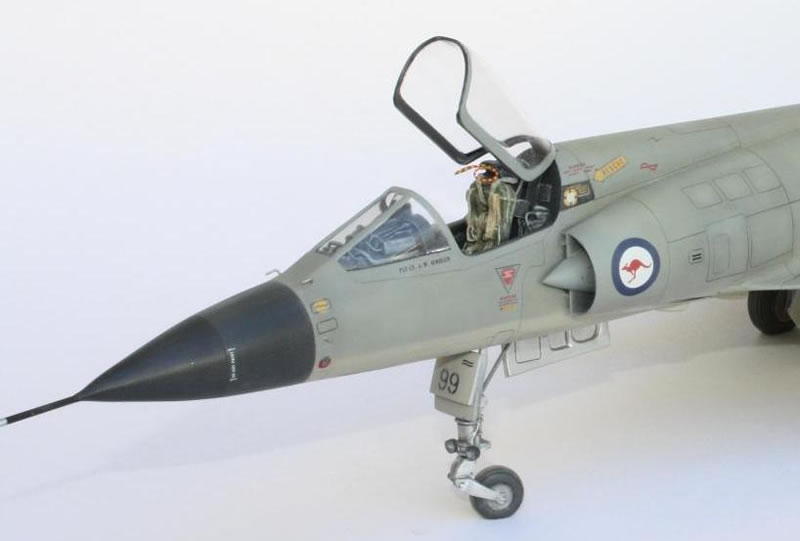
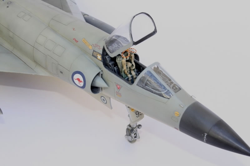
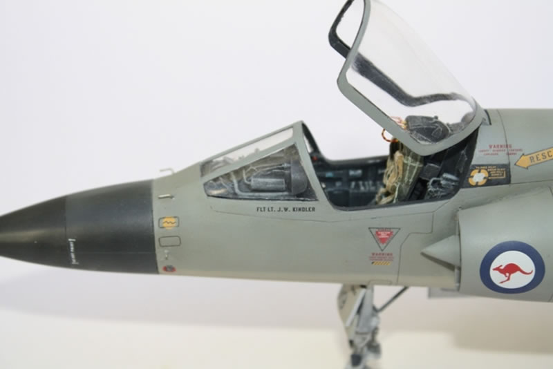
The Fisher Model and Pattern cockpit is quite impressive, particularly the seat, as it is the main feature in an otherwise all black cockpit. The area ahead of the instrument panel shows a few differences between a Mirage IIIE and IIIO, with the latter requiring the addition of a few more exposed cables and wires. These were made from thin solder and soft copper wire.
Intakes
The general shape of the intakes is good. For my purposes, I felt that all they needed was to have the leading edges of the inlet and tip of the central cone sharpened with a file as any further work inside is almost impossible to see. For those with the inclination, the central cone also needs a small inspection panel added just inside the mouth of the inlet. Beneath the inlets, I cut out the gun blast troughs and replaced them with aluminium tube. However, I left out the guns as Australian Mirages often flew without them, instead opting to carry extra fuel in the gun bay.
Fuselage
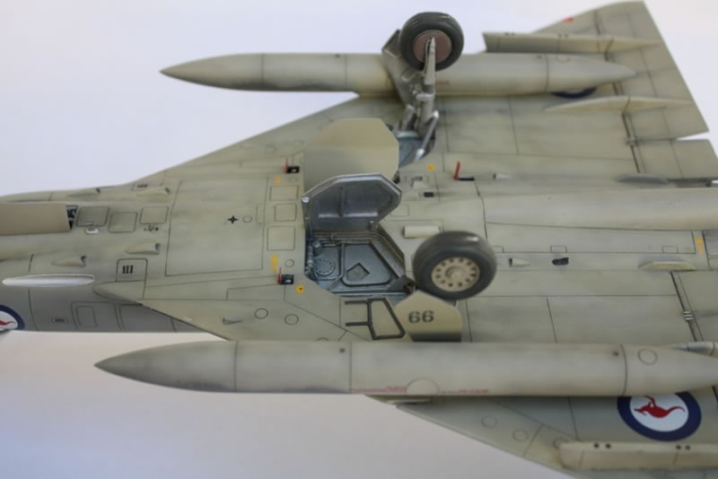
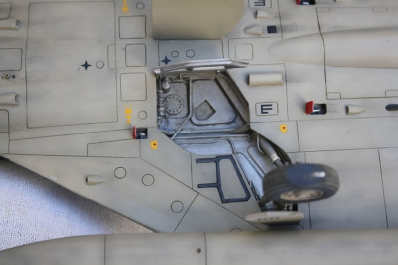
These are large parts that are quite thin and flexible, so before joining the fuselage halves I installed reinforcing strips for the upper and lower seams. I also braced the fuselage vertically between these strips to reduce flexing later on in the build. I opened up a small oval outlet mid-way down the starboard side, engraved a few vents in the upper fuselage area both at the mid-point and at the rear and, most significantly, split the wing roots to make them significantly thicker. This was done by cutting almost the full length from leading to trailing edge then progressively wedging this open with scrap plastic, up to a maximum of 3mm beyond moulded dimensions in the vicinity of the wheel wells. The existing wheel wells were then removed and replaced with scratch built items extending much deeper into the fuselage. However, these weren’t detailed until the wings were added later. This modest increase in thickness (still not as much as it should be) is enough to take the wheel wells into the realm of plausible dimensions.
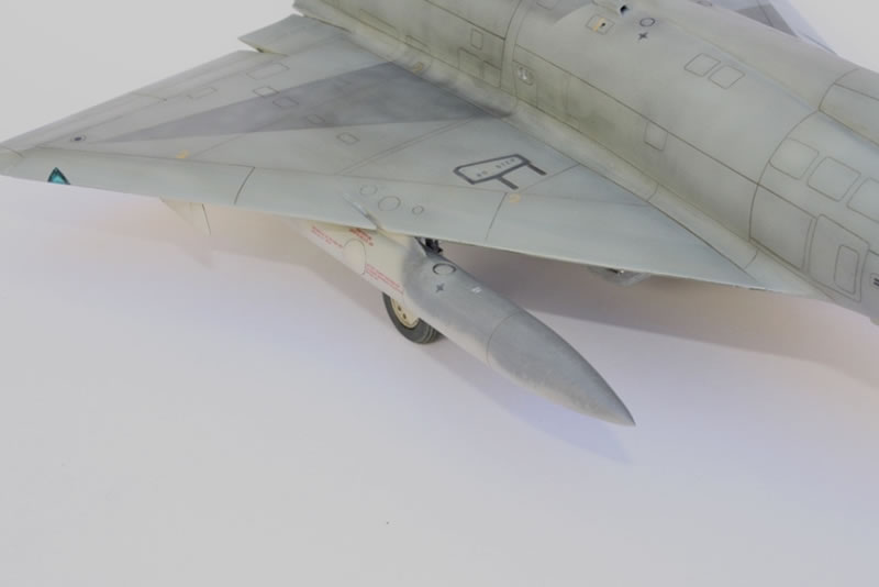
Wings
Again, these large parts need a little more support, so a wing spar from brass rod gave both the required rigidity and permitted a little bending to achieve the correct anhedral. When on the ground, a Mirage’s flapperons drooped, so these were separated from the upper surface, while those for the lower surface were simply scored along the hinge line and bent. The existing wheel wells were removed and replaced with scratch built items extending the full (increased) depth of the wing. They were then detailed with plastic sheet and soft copper wire to reasonably match reference photos.
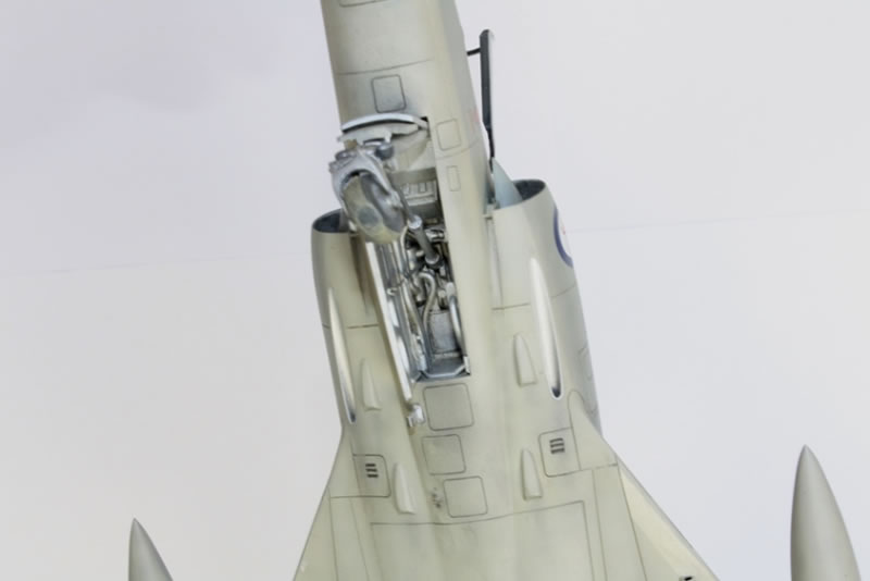
The Blunt End
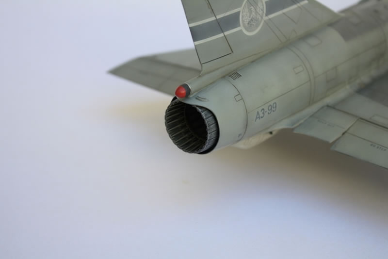
The Revell exhaust is extremely simplified. While I initially considered the magnificent offering from Matterhorn Circle I simply couldn’t get one. However, a passing comment in the Red Roo guide to building a Mirage, lead me to acquire an Aires F-104 Starfighter exhaust. It’s the right diameter, has the right basic structure, but the outer petals are a little long. Solution – shorten the outer petals by about 5mm and smooth out a few small details on the outsides. Although the result isn’t a perfect representation, only a true Mirage aficionado will notice the difference. Above the jet-pipe the under-nourished protrusion is meant to be the braking parachute housing. This was replaced with 6mm plastic tube, tapered top and bottom to fit under the fin. The extra diameter doesn’t affect the fin – as it is separate from the fuselage, a few spacers from scrap plastic will widen it to match the new fairing.
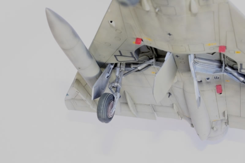
Undercarriage
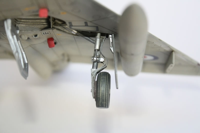
The main undercarriage in the kit is extremely thin and vaguely moulded, so most of it was replaced. This was done with various diameters of brass and aluminium tube, with the various brackets replicated by wrapping plastic strips around the legs. The nose wheel leg was largely used as supplied in the kit, but adapted to fit into a scratch built nose wheel well. All wheels were made wider by adding a sheet of 1mm plastic between the kit supplied halves. The demarcation between wheel and rim was engraved by rotating a pair of dividers to make the join more prominent. For those wondering what the little red access hatches near the wheel wells are, the valves inside released hydraulic pressure and allowed the undercarriage doors to be opened on the ground for aircraft servicing. Both these access hatches and the undercarriage doors were always left open until being readied for the next flight.
Painting
All painting was done with Humbrol enamels. To achieve a weathered finish I first painted the base colour at about the shade wanted for the end result. Over this went a random pattern with black added to the base colour, along with post shading around access hatches (but not fixed panel lines). Finally, this was given a third layer, again random, using the base coat lightened with white. Any areas where the contrasts remained excessive were further toned down using the final lightened shade applied in streaks in the direction of airflow or rain.
Markings
Being a special edition boxing, all markings used were those supplied in the kit. The only one to present a bit of a problem was the stripe and squadron crest on the fin, which used an inaccurate combination of white and very dark grey. These were toned down with a thin application of the upper surface camouflage colour. However, all markings performed very well, responding nicely to Micro Set and Sol. Humbrol satin Clear finish was used as the final coat, lightly buffed with Micromesh polishing cloths. The leading edges of the wings and fin were left gloss to replicate the lacquer applied to these areas to decrease drag and provide a more durable finish.
Conclusion
Overall, this was a case of adding detail to a well proportioned but fairly blank canvas. The end result is a pretty good representation of an aircraft that still manages to look fast even when it’s standing still. The bonus is a unique but business like paint scheme that, reportedly, was very effective at disorientating the opposition during the last years of the aircraft’s front-line service with the RAAF.
References
- “Mirage IIIO Colours and Markings”, Paul Mason and Darren Mottram, Mushroom Model Publications (an amazing book).
- “The Modeller’s Guide to the Mirage IIIO/D”, Gary Byk, Red Roo Models.
© Mike Prince 2014
This article was published on Thursday, March 13 2014; Last modified on Sunday, April 03 2016