
Foiled Hasegawa 1/32 F-104G
By Ken Friend
Most of this article was originally posted in the forums in 2011. The post was removed from the forum at my request due to some potential conflicts with other articles I was writing at the time. I have edited the post into smaller segments so questions and comments can be addressed. The original post followed the build of a 1/32 Hasegawa F-104G and the development of some techniques that can be used to foil and finish some difficult areas. The mundane "build" information has been excluded in order to focus on information that can be used to answer some of the questions I see in Brian's builds about the foiling process. Brian has taken the foiling process to new levels, and this post is meant simply as additional basic information from another "Foiler"...
Ken
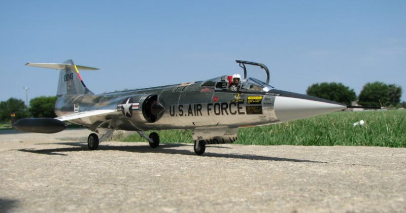
Foiled Hasegawa "Lukewaffe" F-104G
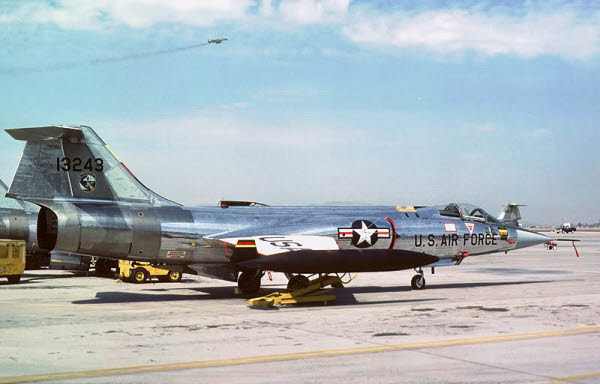
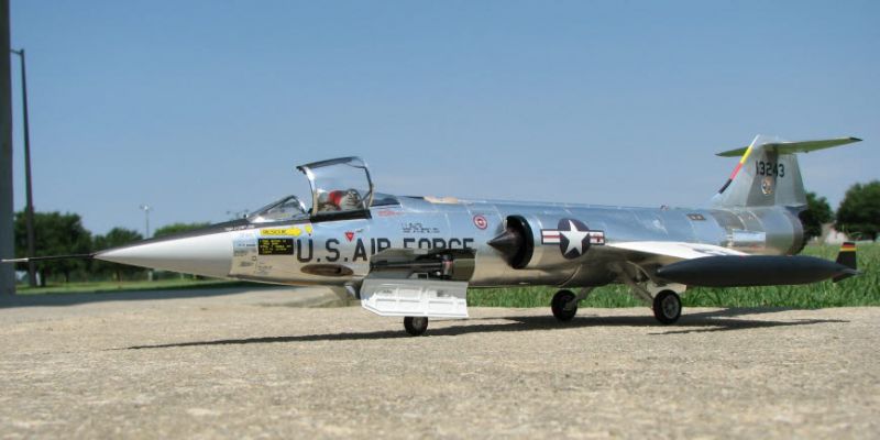
Although I was an Aviation Metal Smith in the Navy (painted planes), I have always had a soft spot for natural metal finished aircraft. There are some planes that just look good, no matter what finish, or if they are just sitting still on the ground. Many folks think the F-104 is one of those, and I happen to agree. The bird I was trying to replicate is from the "Lukewaffe" planes used for training German pilots based at Luke AFB. These planes had a natural metal finish and US markings. This one (TN 13243) was always kept in great shape and, according to the Luke website, was used in the movie "The Right Stuff'. (Note the German colors on the tip tank fin and the leading edge of the vertical stabilizer.) Naturally, I picked one like this so I could foil it! I also found there were other areas that made for a troublesome build, but the solutions were similar to the foiling process.
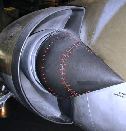
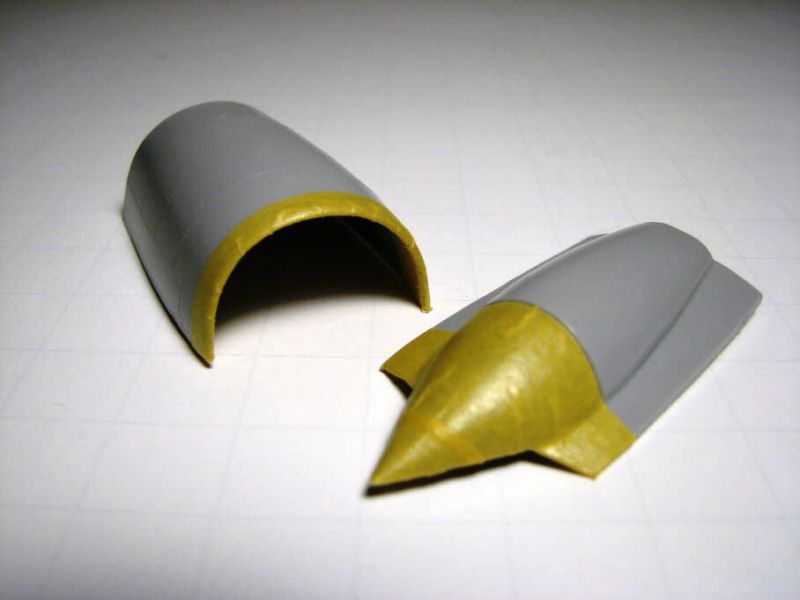
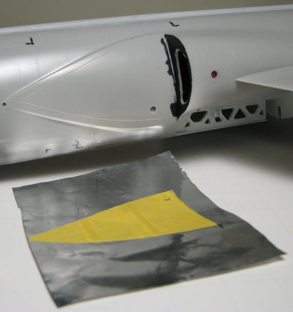
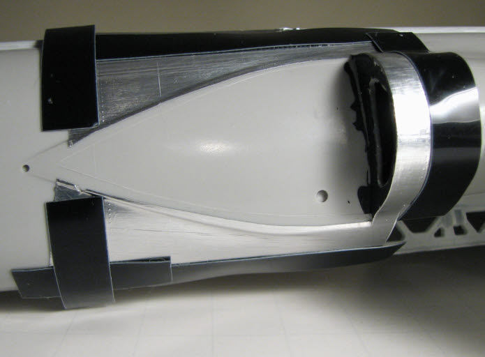
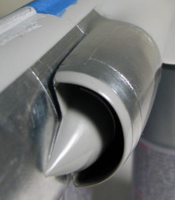
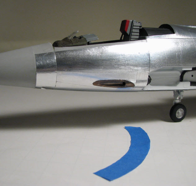
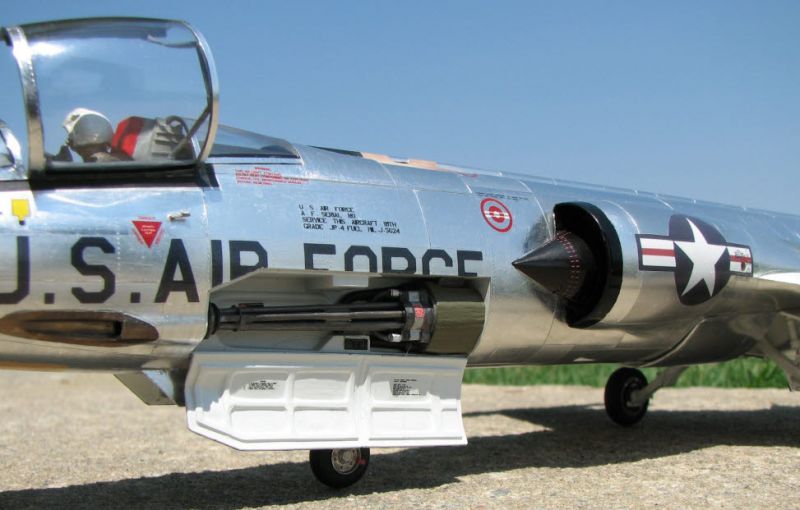
Where the build started to get interesting was when I was trying to decide just how to do the intakes. I wanted to avoid having to hand-paint each of the fastener markings since they were so small. Each intake would be a combination of color and foil.
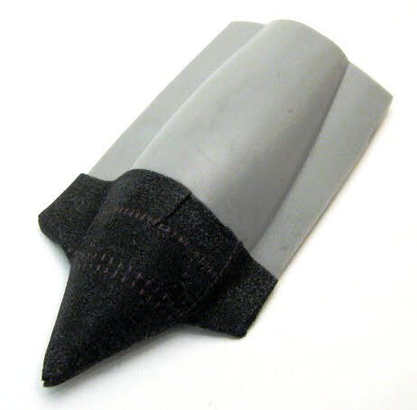
Assembling the two-piece intake while adding the inside detail caused a lot of head scratching. The solution shown here is not typical, but seemed to work well. I decide to "paint" the area with decals...
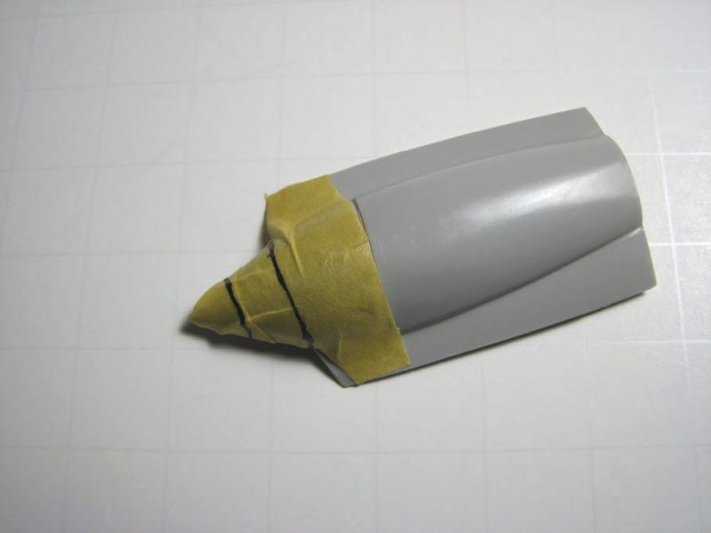
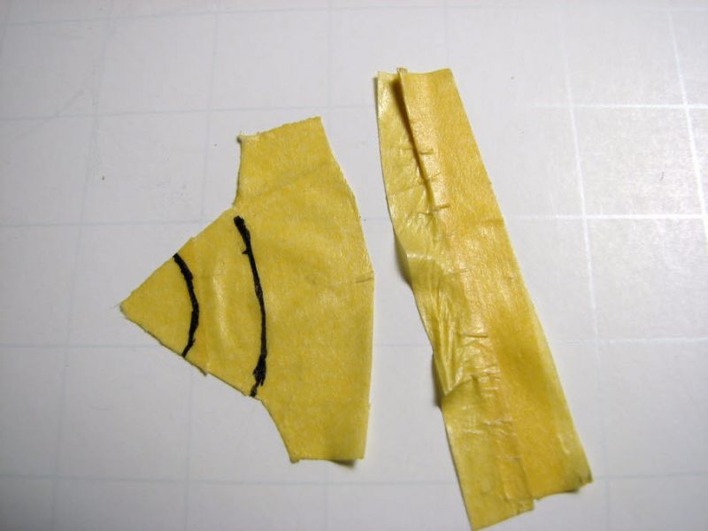
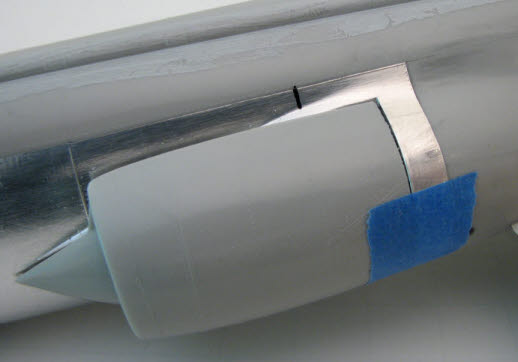
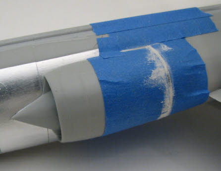
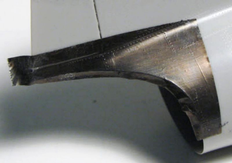
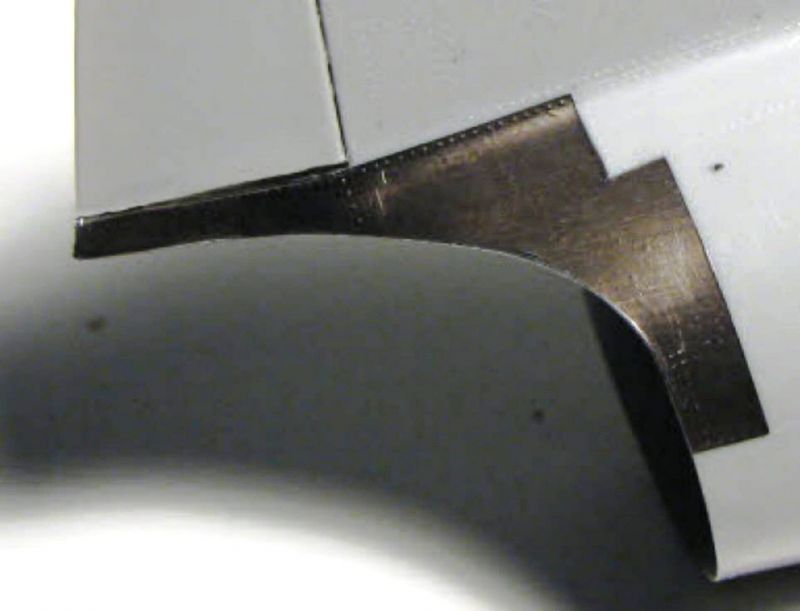
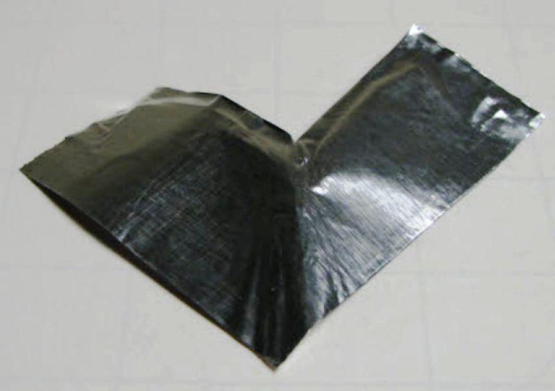
The first step was to get a pattern for the decals. A simple way to get the proper shape for a compound curve is to press some Tamiya masking tape firmly over the surface, trim it to size with a sharp blade, then carefully peel it off and lay it flat. These images show the tape after it was applied to the inlet pieces, and after it was removed. The curved panel lines were added as straight(?) lines while the tape was on the parts. When the tape was unfolded, the lines were curved. The pieces of tape were then scanned into a JPG image.
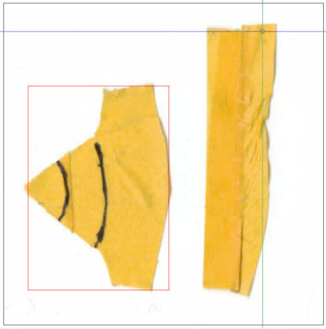
After scanning the tape pieces, TurboCad software was used to scale them to the correct size for printing. Any graphics package with scaling capabilities can be used for doing this work. The red box in the image is the measured size of the original tape piece.
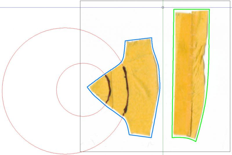
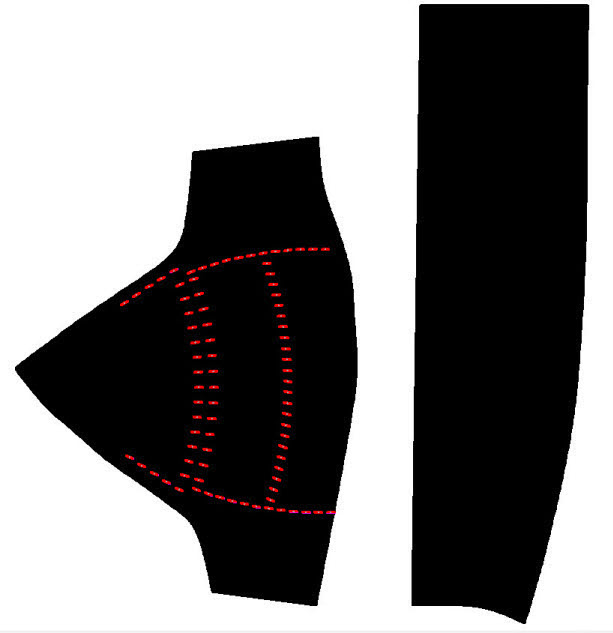
After the images were sized correctly, outlines of each piece were created, slightly larger than the originals. (You can always trim, but you can't always stretch.) Real (not sketched) circles replaced the hand-drawn black panel line arcs. Once the new outline was completed, a black fill was used to get a better look. Fastener markings like those in the original intake picture were added using standard graphic techniques.
Once the graphics looked somewhat like the real thing, they were printed on plain paper, cut out, and sprayed with water. Forming the wet paper over the contours showed a couple areas that required touch up, but also showed the decals would fit correctly when printed on decal film. The paper pieces puckered somewhat, but decal setting solution should take care of those irregularities once the decals are applied.
The first printout on decal paper was purely a test run on clear decal film. Decal paper for both Inkjet and LaserJet printers is available through several sources on the Internet. The clear decal film seldom varies in quality, but I have found that the white film can sometimes be translucent instead of opaque. Decals printed on either clear or white decal paper will look identical until they are removed from the backing. That's when it becomes obvious that the color layers are very thin. Decals on the clear background almost disappear when remove from the white paper backing. However, applying different printer settings and double printing can help bring the color density to an acceptable level. Clear matt, semi-gloss, or gloss acrylics can be applied over the printed decals to seal the decals, giving a choice of the final surface finish.
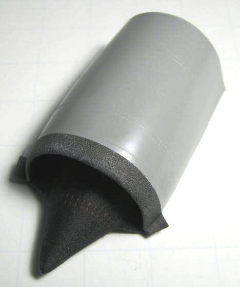
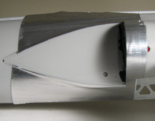
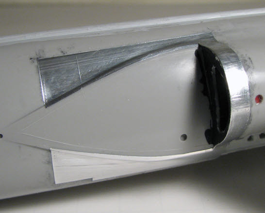
After allowing the decals to set, the screw markers were not positioned on top of the raised detail, so that had to be corrected. Once the basic decal design was finalized, the bare parts could be assembled and trimmed, and the new decals added for the extra internal detail. This image shows the test decal in position. The final decal would be trimmed and tucked-in to the tight spots.
Using a similar process, the next step was to foil the rest of the complex shapes around the intakes. The Hasegawa kit has raised panel lines, which makes foiling a little more difficult. I would much rather that the panel lines and rivets were recessed, but these are very fine, and SHOULDN'T cause too many problems. Light sanding leaves enough outline to be seen through the foil when it is applied, foiling in panels instead of larger sheets makes the slightly raised lines disappear.
Foiling isn't like painting where everything is glued together then sprayed with paint. Gluing the intakes in place right now would cause a nightmare later on while trying to foil the backside of the intakes and the area of the fuselage that is behind the intake.
Keeping the left to right symmetry of foiled panels is usually an afterthought, and can make a foiled model look more like a patch quilt if not maintained. The panel materials on the right side of an aircraft, are generally mirror images of the left side, and vice-versa. When making panels that ARE mirrors, make 2 from the same piece of foil. Use a piece of foil that is twice the size of the area to be covered. Fold the foil in half and cut the desired pattern slightly oversized of the area to be covered. Separate the pieces along the fold line and apply both at the same time. Telling yourself "oh, I'll do that one later" causes endless problems when you can't find one of the pieces you so carefully put in a place you'd be sure to find later...
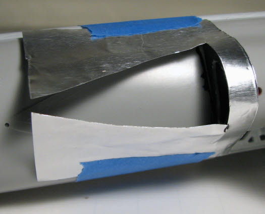
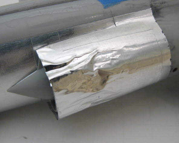
Extra Heavy Duty Reynolds Wrap was used around the intakes, since I anticipated a need for a little sanding for fit/finish. In the first picture, the panel to be covered was marked as defined by the raised rivet and panel line detail. Note that this area is not flat. Tape was also applied to the area where the intake would be mounted. After trimming the tape back to just inside the intake contour, the tape was transferred to a piece of foil I thought was big enough to cover the panel area. Boo-Boo #1! The piece I cut ended up being too small. OK, so that doesn't seem to be important. I only mention it because it is easy to under estimate the size of the piece of foil required when you are trying to fit it to contours. Unfortunately, it usually doesn't happen until after you have cut it to shape and applied adhesive...
After cutting out the tape pattern, the foil was taped to the model to make sure it would fit the area and have relief where it should. After assuring the fit, the piece was removed and adhesive applied. It is important to get the adhesive smooth. Adhesion is best right after the adhesive goes from white to clear.
NOTE ADDED 20 July 2013: When this article was originally posted, foil adhesive was smoothed with thin-edged body filler paddles. Brian's use of an airbrush for applying foil adhesive is also a great way to get a smooth layer of adhesive.
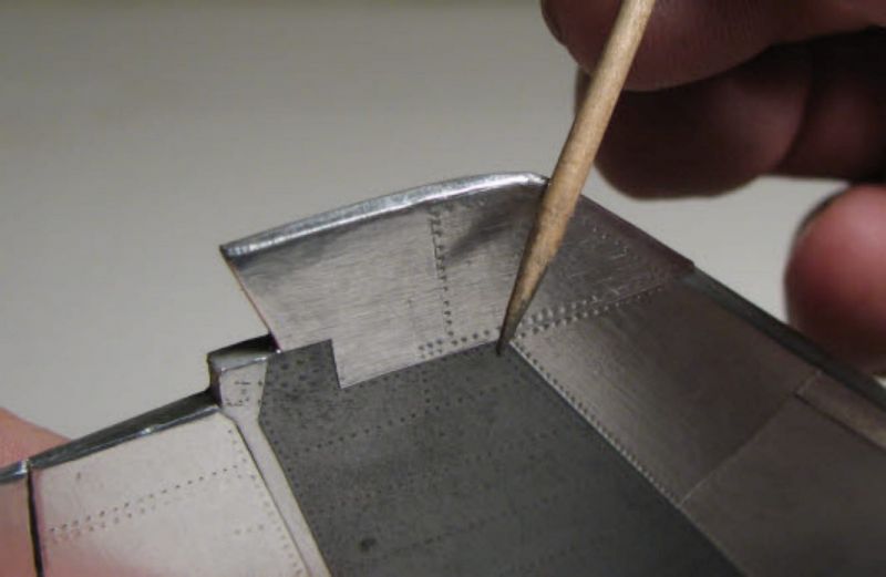
The foil was placed back on the model starting with the highest points and working towards the outer edges with a piece of hard balsa. Hard and soft balsa both work well; it is just a matter of preference. Regular wood will catch, scratch, and tear the foil. The final shaping of the tight spots was done with a toothpick. The semi-circular outer edges of the intake were trimmed with a slight overlap that was folded over the edge of the intake. The overlap will be sanded back to the plastic edge later on.
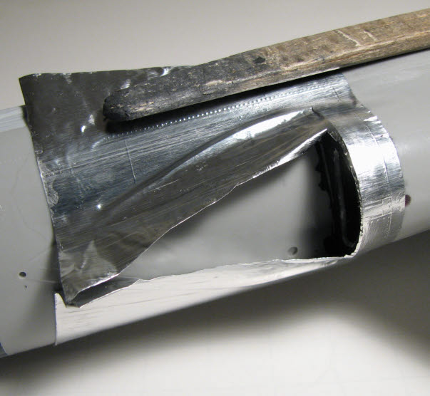
Dymo label tape can be used to define the edges of the panel, and It makes a good edge to "lean" on with and X-Acto or razor blade. Dymo label tape has quite a bit of tackiness. Using it here on bare plastic was OK, but if it is applied over foil, it will sometimes lift the foil on removal. To avoid this problem the Dymo tape can be placed on a piece of low adhesion masking tape. When cutting the foil try to do it in one straight cut. Locating an old cut line is difficult, and often leads to foil "hair" around a panel line. Make sure you have a good stock of razor and X-Acto blades; keeping a sharp edge will minimize tearing. The last picture here shows the complete panel once it has been rubbed down and trimmed. Total time here was about 1/2 hour...
Cleanup after setting a piece of foil is imperative. You can safely use 90% isopropyl alcohol on a cotton ball to clean up any adhesive residue left behind. If you happen to lift a corner or edge, let the alcohol dry and apply a small amount of foil adhesive. Let that dry, then smooth the edge down again.
Boo-Boo #2! I cut a piece of foil to put on the panel forward of the one I had just done, put adhesive on it, and started to smooth it...CAT HAIR! Once in a while you can carefully lift the foil (if you have not pressed hard yet) and capture an errant hair, but usually it is best to just lift the foil, clean the area with alcohol, and make another piece. Foil adhesive is a magnet for any dust, animal hair, or foreign object. It is best to turn off all ceiling fans when applying the adhesive. And sneezing is forbidden! In this image the rest of the fuselage area in front of the intact spike has been covered with a new, cat hair free, piece of foil.
The intake parts were cleaned and thin foil applied to the backside. Thin foil was used to minimize dimensional changes caused by the thickness of the foil. I tried to get the intake pieces to fit well enough that I wasn't going to have to do much, if any, filling and sanding. After trying the fit, I realized I had gotten ahead of myself. The seam between the intake and fuselage was going to be way too wide. Although the fit was good, I had been tempted by wishful thinking. You'd think I would know better... So, I get to go through Boo-Boo #3...
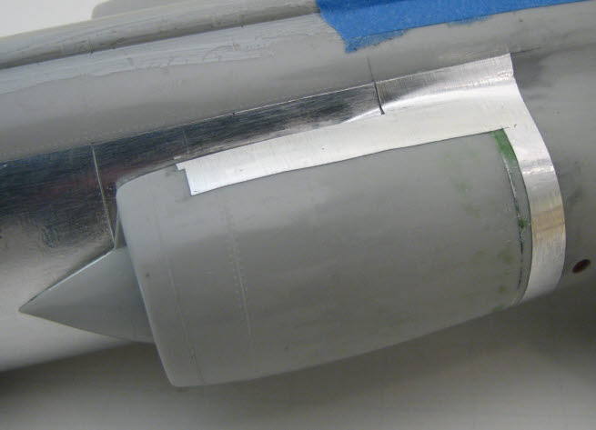
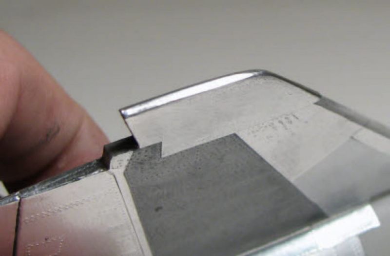
The foil that was laid next to the fuselage/intake joint had to be removed so fitting and finishing could be accomplished. I marked the nearest panel line on the top and bottom of the fuselage, cut along those lines, and removed the foil aft of the fuselage/intake joint.
Sanding the fuselage/intake joint without protecting the raised detail would eliminate the detail completely. I used safe release masking tape to protect the surrounding area after attaching the intake to the fuselage. The seam was filled and sanded smooth.
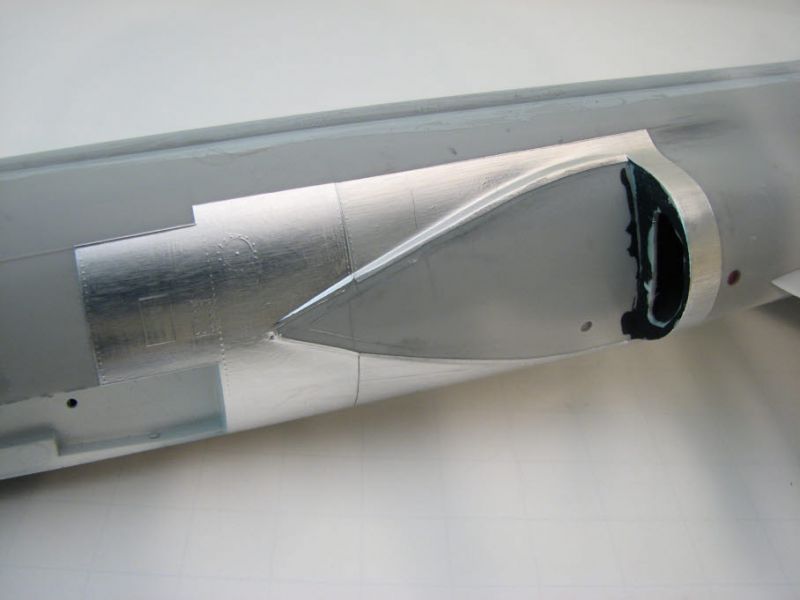
Foil can be used as a tool also. The reflection of a highly polished surface will show underlying imperfections in a heartbeat. Small pieces of Bare Metal Foil applied over filled seams, sink marks, repaired knock-out pin locations, etc. is a good way to tell if the area is smooth and matches the surrounding contours. In this case an old piece of Ultra bright chrome BMF worked well for determining if I had a smooth interface between the intake and fuselage on both the upper and lower surfaces. A good close-up picture assured the seam was smooth. BMF is also a great masking tool.
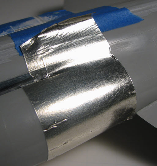
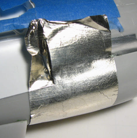
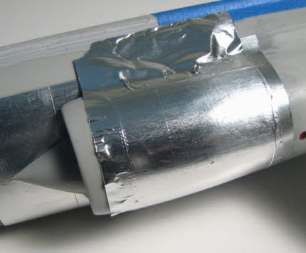
Applying large sheets of foil to a model still makes a nice model, but does not represent the way airplanes are built. Aircraft parts are made from a variety of materials and as many alloys of each. It would be tempting here to attempt to cover the whole intake with one piece of foil. However, it is actually easier to do it in multiple pieces since this is a compound contour which will cause the foil to wrinkle where it needs to bend in multiple planes. So, I started with a smaller, more manageable piece of Extra Heavy Duty Reynolds Wrap. The edges were smoothed this time, and the center allowed to wrinkle. The piece was placed on the model, smoothed, and trimmed along the panel lines with a single-edged razor blade.
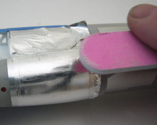
The second piece followed the internal contours of the first piece, but still covered an area with a compound contour. This time the edges of the foil were allowed to wrinkle, and I got some unavoidable wrinkles around the bottom of the intake. That's why thick foil was used here. To remove the wrinkles, a nail board was used to sand close to the surface, then the remaining wrinkles were worked down with progressively finer wet-or-dry sandpaper. Once the area was smooth, it was polished with Crest Pro-Health toothpaste (the most abrasive I can find). Regular Crest was next, and Tamiya polishing compound was the final step.
In case sanding a wrinkle actually breaks through the foil, it is not a disaster. A wrinkle that has been sanded through will leave a thin line of exposed plastic. When the foiled area is finished, a touch of Model Master buffing metalizer can be applied with a brush and buffed when dry. The buffed area will virtually disappear.
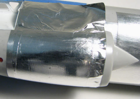

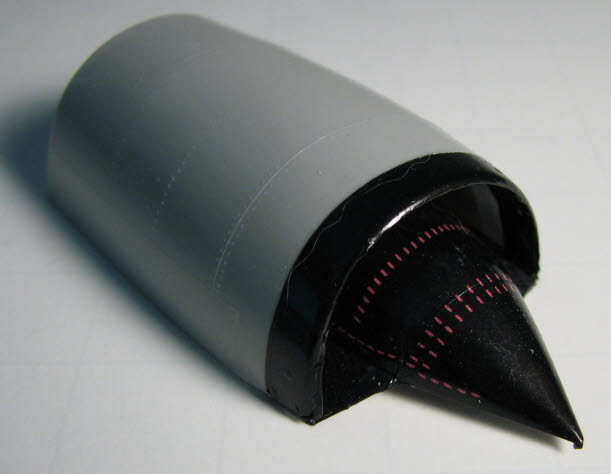
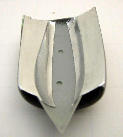
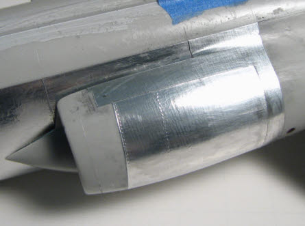
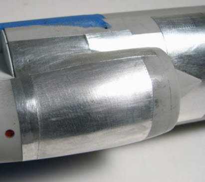
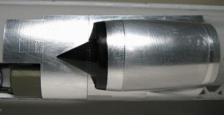
And here is the intake before and after the final piece of foil was added. Each piece of foil was cut from a different brand and thickness of foil. This is the way panels appear on the exterior of a plane even if they are all aluminum.
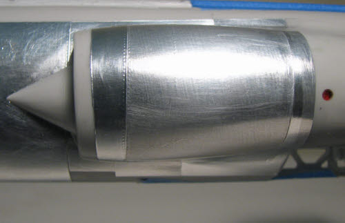
In this image a "draft" decal printed on decal film was applied to get a better idea of the overall effect of the work done to this point.
Some panels have gray or amber tones due to the alloy of the material, the heat treating processes used to develop the alloy, and/or where the panel is used on the aircraft. The fixed panels on high speed aircraft fit closely, whereas access panels might have up to 1/32" clearance around the periphery. The panel lines on NMF aircraft will dull, but don't turn black unless the finish was achieved by buffing the exterior. In that case the black comes from the polishing materials and process. The edges of access panels and openings are burnished to a highly reflective finish with a very hard tool such as a drill bit. This minimizes the propagation of very minute cracks/scratches created during the manufacturing processes.
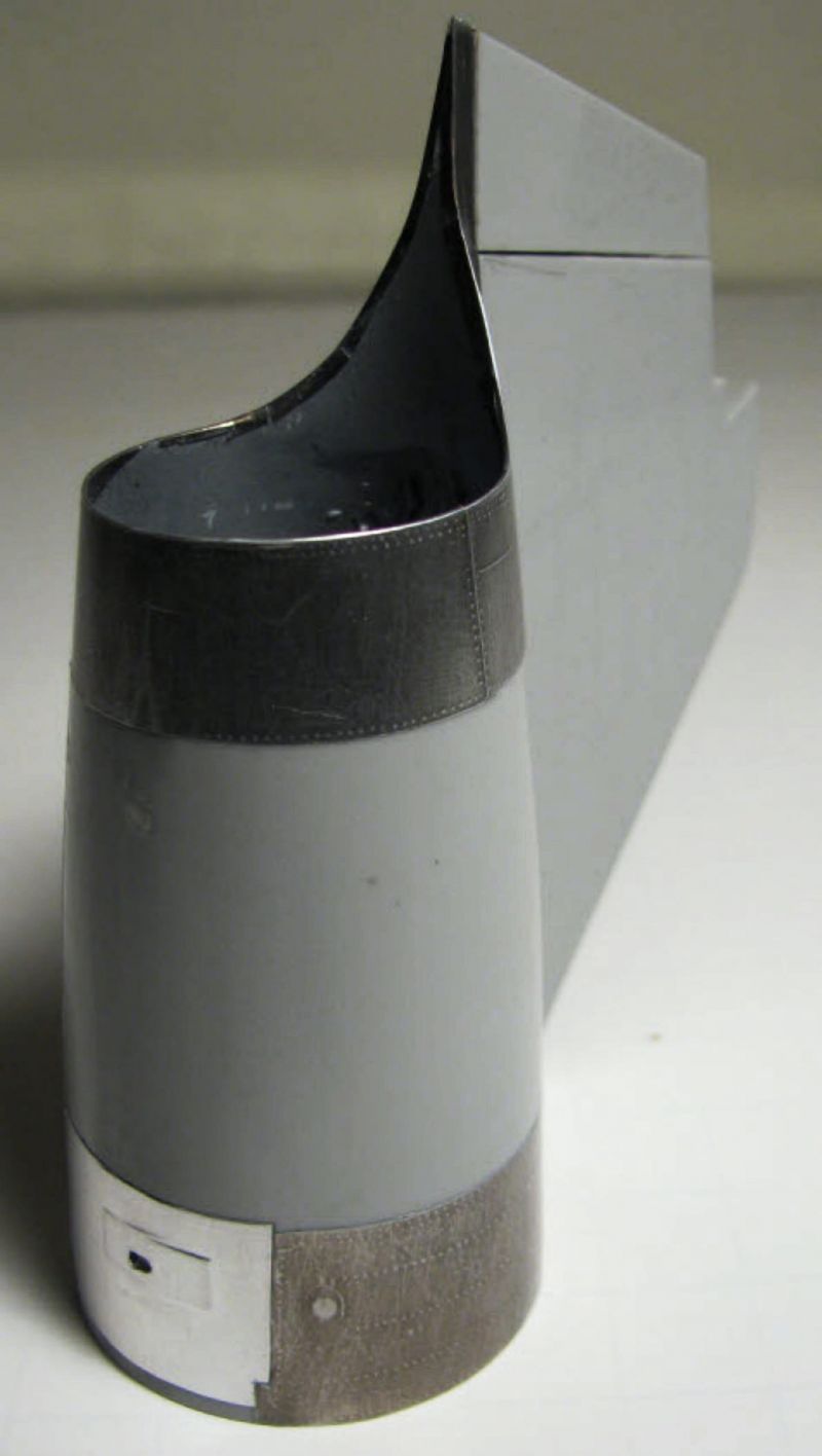
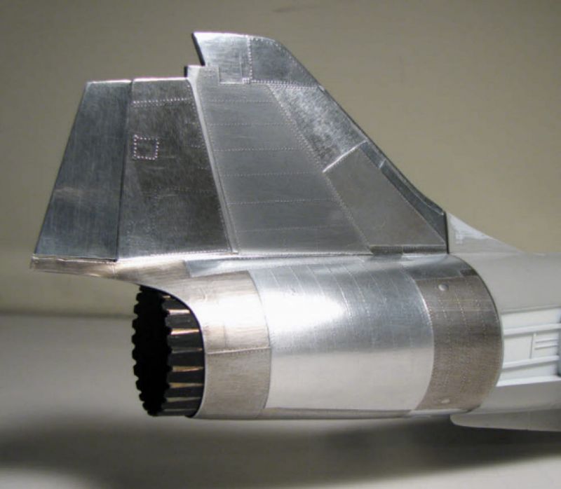
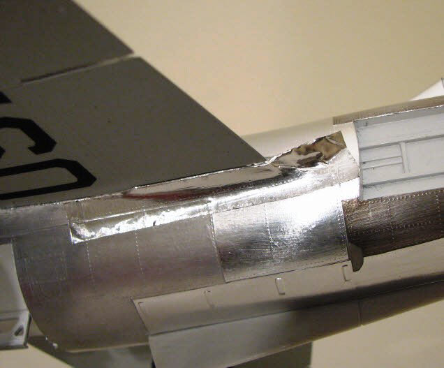
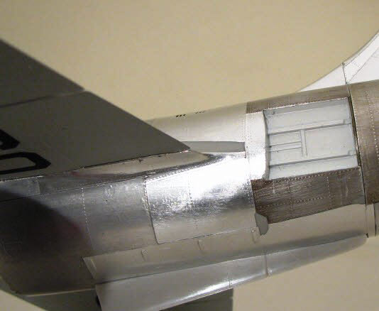
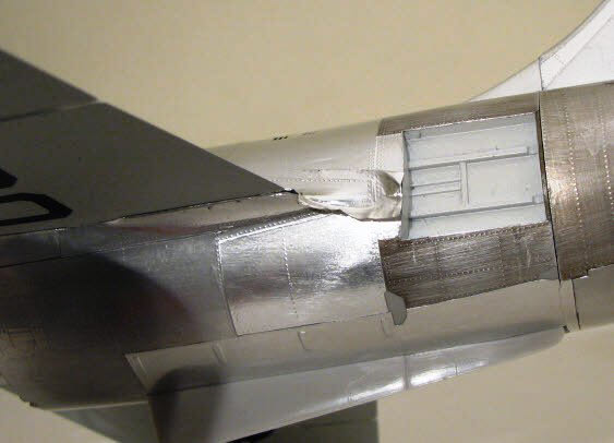
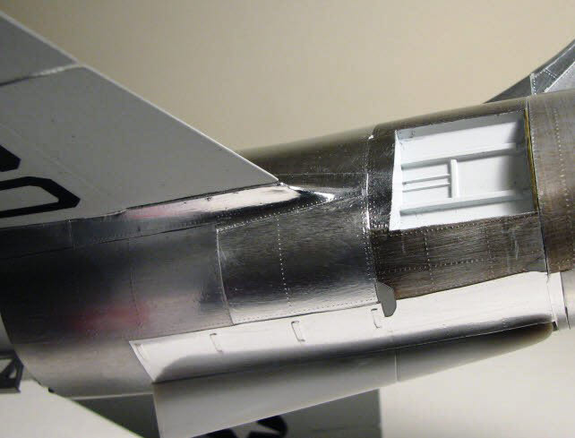
There is one other area around the tailpipe of the F-104 that can also cause some foiling difficulties. I cut a small piece of discolored foil for the high heat area of the exhaust. The piece I am using here is too dark, but will be toned down with a little steel wool after it is positioned. Whenever there is a corner to be foiled make sure the foil extends far enough beyond the edge to completely wrap around the corner. If foil is trimmed right to a corner the edge can be lifted during normal handling; wrapping around the corner assures there are no edges to catch while buffing, etc. The first picture shows the piece once it has been smoothed with balsa sticks and a toothpick. The second picture shows the piece after trimming and wrapping around the edge.
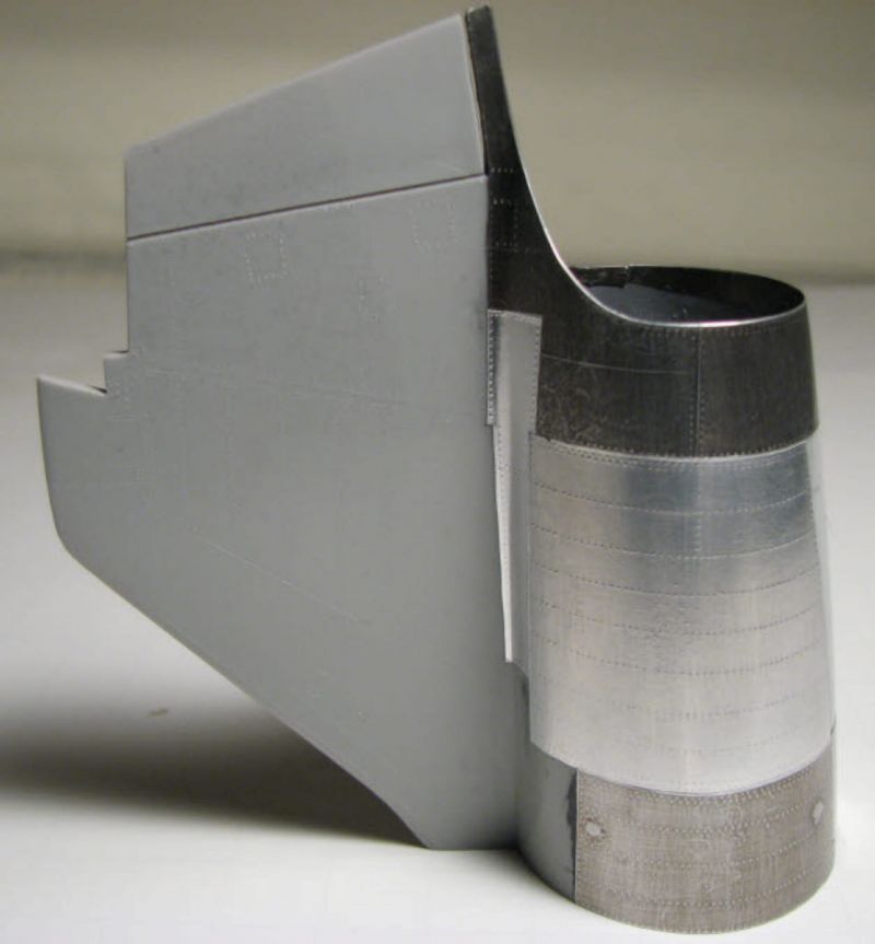
In the following pictures, I have added foil to other areas of the tail section using another piece of discolored foil and a piece of standard foil. This shows the effects of using different foils on each panel. For some reason the tailpipe foil appears darker in the pictures than it really is. Both discolored areas were polished lightly with steel wool to tone down the darkened foil.
Anyone who works with foiled models has their own private "stash" of different foils. That's what makes this so much fun. I used to use Nestles Crunch bar foil until they changed their packaging. I then started picking up foil from wherever I could find it. If you can get them to part with a piece, the foil at Heavenly Hams is absolutely the greatest. I even have friends who save their foil from their barbeques for me; different foods, different colors!
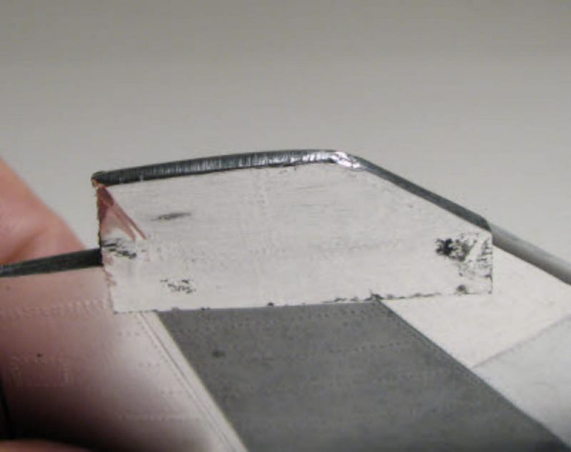
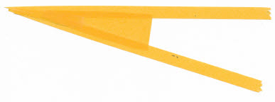
The tips of wings and tail surfaces always present problems, but once you get used to working foil around the contours, it isn't as bad as one might think. Contrary to what might seem appropriate, I used extra heavy foil for this. The first picture shows the tip of the fin that will be foiled. I chose to wrap the foil around the leading edge so it would be smooth; that left just the top to deal with. I cut a "V" shaped piece to cover the area, again looking for the raised panel lines. The piece was pinched tightly around the upper contour and smoothed.
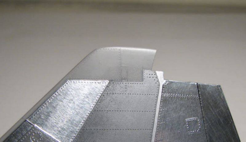
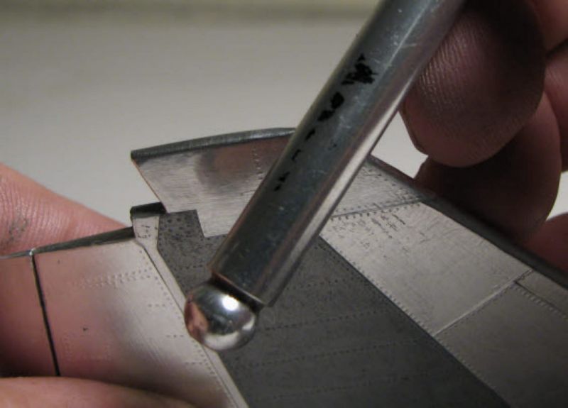
The excess foil was trimmed back slightly then folded over the edge. A razor blade was used to trim the excess, and the overlap smoothed with just finger pressure. The area was trimmed to the panel lines and the top of the fin smoothed with a toothpick. This is where the malleability of the foil comes into play. The final burnishing was done with the aluminum handle from an X-Acto knife and just a touch of Vaseline to prevent tearing. The foil will "smear" just enough to cover the seam.
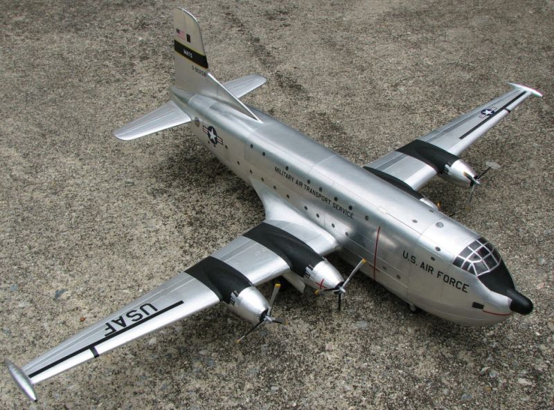
And here is the tail section of the F-104 as it appears with the rest of the panels foiled. The "wear" areas of the AB nozzle feathers have also been foiled. There is still work to do on it. The 2 bumps are the Navigation lights that have been covered by the foil. A piece of sharpened hobby tubing of the right size will be used to cut the openings for the lights and a small circular piece of foil will be added around the lights once they are made flush with the surface. Always make sure you can find details like this once you have covered them with foil. Since foil shows every underlying detail, a simple lightly scribed outline of the detail will suffice. I once did a 1/72 C-124 with flush windows, covered it with foil, then couldn't find the windows to open them back up...DUH!
The tail section was foiled while it was easy to handle. It is now ready to join to the rest of the fuselage. A little caution is required when joining two sections that are already foiled. After joining the sections, you will have a hard time resisting getting in there and smoothing everything out. Don't try to smooth the foil at the joint right after gluing. The underlying plastic will be soft from the glue, and the resulting dents will be hard to fix without stripping the foil and redoing the damaged area.
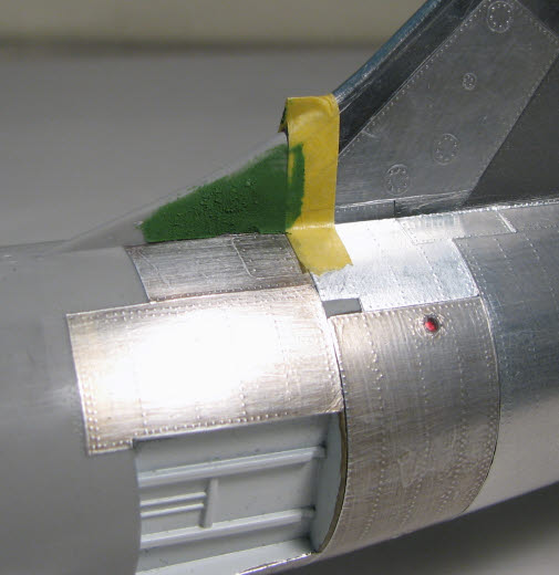
As I mentioned before, foil is a great tool when used to see if seams and contours are well blended. I tried to foil the very first part of the vertical stabilizer, and sure enough, I found a sink hole I hadn't seen before. So, this is one of those OOPS! that I will have to correct now that I have added foil right up to the edge of the area that will have to be filled, sanded, and re-foiled. I used a little Tamiya masking tape to protect the foiled area while I put some filler in place. When I start sanding, I will put more tape on the surrounding area and make sure I don't sand through to the foil.
And here is another area that sometimes causes problems for folks who haven't done foiling before: the wing root fillets. The temptation is to use a single piece of foil, and if the blend radius between the wing and the fuselage is either very small or very large, it is worth a try. However, a lot of gray hairs can be avoided by simply covering the area With 2 pieces of foil. In the first picture I have applied a small piece of foil to the lower side of the fillet and rolled it up about 1/2 way onto the fillet. The foil was then trimmed to the parting line that separates the lower and upper surfaces.
Next an upper piece was added and rolled over the lower piece. When the upper piece is rolled over the lower piece the edge of the foil is not visible from normal viewing angles. If the lower piece were rolled over the upper piece, the seam would require more work to make it disappear.
When trimmed to shape and feathered, the seam all but disappears.
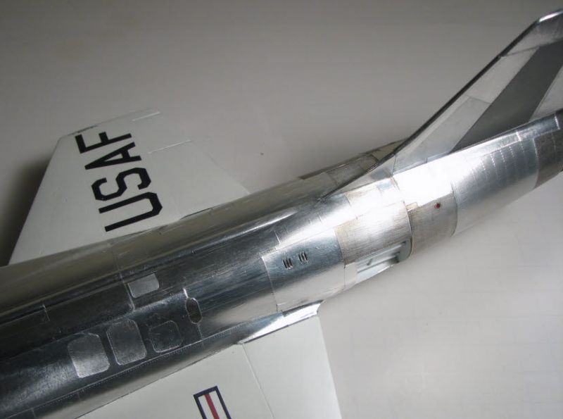
I have not abandoned Bare Metal Foil. BMF is great for adding another layer of foil in the form of extra details. This is where foiling starts showing its most reward. This high light angle picture shows how varying pieces of foil that are applied to access panels can add to the realism of the finish.
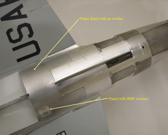
The added benefit of individual panel foiling can be seen in this picture where identical panels appear on both sides of the fuselage. One has 2 different BMF overlays, and the other has none.
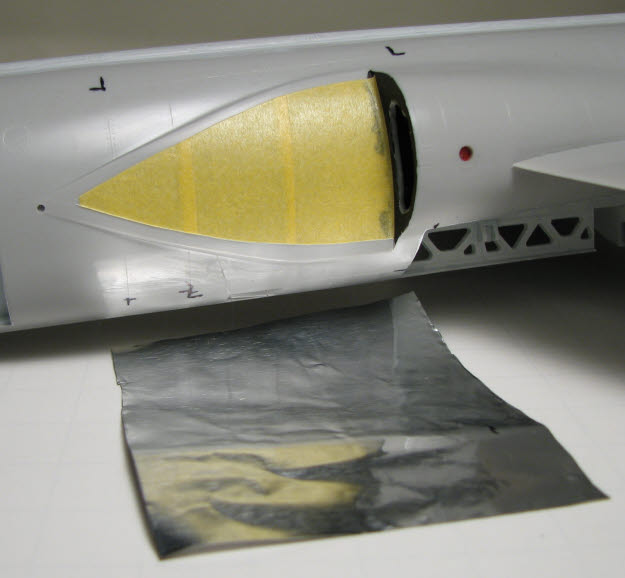
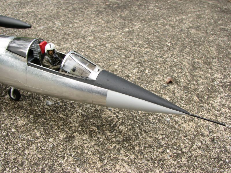
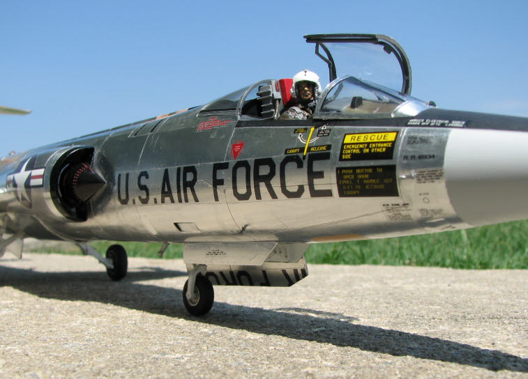
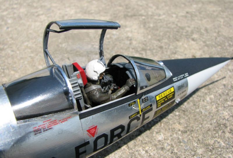
Once in a while I like to put the other parts on the model and take a look at the overall effect. I also try to take a picture that replicates the lighting conditions of the original real life plane pictures to make sure I am at least coming close to what the real plane was/is like. The cone-shaped sections like the area just in front of the 104's cockpit are a good example of an area that can trouble new foilers. Using the same technique that was used for the intake decals, a piece of low adhesion masking tape was wrapped around the section and cut to the panel lines. This will work just as well if you have to use more than one overlapping piece of tape. When the tape is peeled off it can be used as a pattern for a piece of foil to fit the area. The foil was cut slightly larger than the tape to allow just a little trimming material. In this case the tape pattern was also used to mask the foiled area before painting the light gray on the underside of the nose.
After finishing the gray, I made a tape pattern of the anti-glare shield area. I would rather not mask things like anti-glare shields simply because I usually have a lot of cleanup around the edges. So, I make decals of the area and overspray the sealing coat with flat acrylic. Some would say "that's cheatin'", but so long as the last coat is paint, I can live with it. I scanned the pattern, brought the image into CorelDraw and made a new, filled image in black. The image was printed on clear decal film, and sealed with Flat Krylon Crystal Clear Acrylic. The resulting decal gives nice crisp lines with little to no trimming and cleanup.
Bare Metal Foil was used on the canopy frame. This an area where BMF excels in its ability to capture and fit intricate details. I used strips of BMF on the 104, but sometimes use a larger piece on smaller canopies. The larger piece can cover the entire canopy if you want, then the frame can be cut out with a good razor blade. If you have an older piece of BMF that doesn't want to stick well, or a corner that wants to lift, just use a little Microscale Metal Foil Adhesive as you would for the thicker foils.
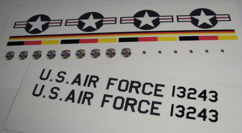
Since this kit was the Hasegawa F-104G with camouflage colors and markings, there were only a few of the decals that were usable for this version. Getting the right markings was a challenge since this particular bird seems to have undergone several different paint schemes. I had some good service decals that only required removing some of the foreign language that is incorporated with the English. Bottom line; all the marking decals I couldn't find in kits had to be created from scratch.
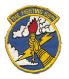
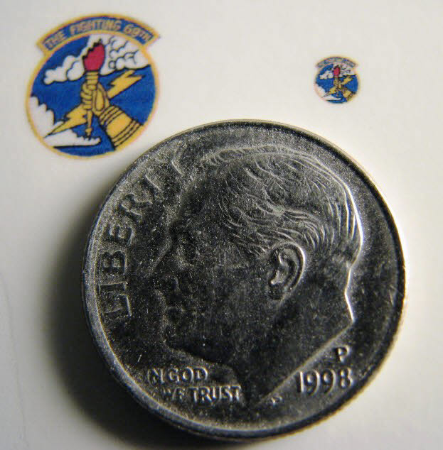
Fortunately there was an image on the Internet of the "Fighting 69th" squadron patch. This logo was used on the vertical stabilizer of this F-104. The logo was brought into CorelDraw then re-scaled to the proper size and replicated on a decal sheet. The new decals were then printed on an inkjet printer.
I imagine most modelers do this, but whenever I get a new kit, the very first thing I do is scan the decal sheet at 600 dpi minimum. If I do have a problem while applying the original decals, I always have a backup copy.
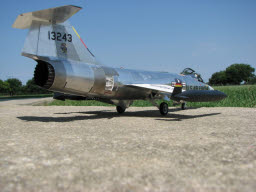
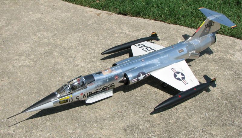
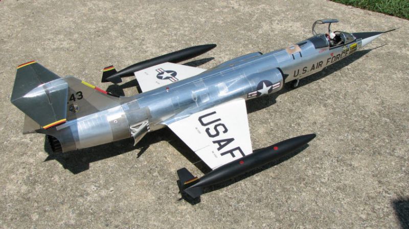
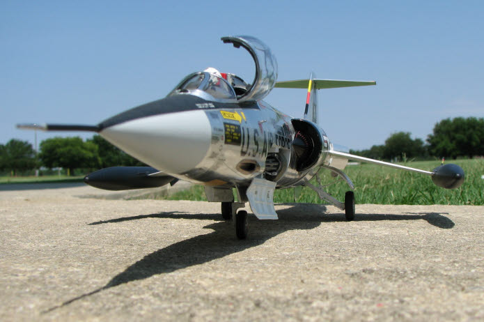
Here is the completed F-104:
Through several competitions over the past few years, I have learned that there are not many folks who are willing to try covering a model with aluminum foil. When I asked a judge "why not?" he said, "I don't think anyone wants to take the time to learn." Since there is no set way to apply a foil finish, there is not really that much to learn. Foiling does take extra time, due to the application of individual panels instead of broad areas at one time. Just to give an idea of the time involved, it took me a little more than the weekend to complete the tail section of the 104.
The only reason I re-posted this article is to help folks understand that foiling is actually a lot of fun, and that it is not really that difficult. What I haven't told you about the tail section of the F-104 is that I have discarded a few pieces of foil after applying them and not caring for that particular piece in that particular spot. That's where I like foiling over painting; I simply peeled that piece of foil off, and replaced it with one I liked better.
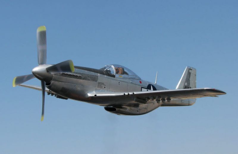
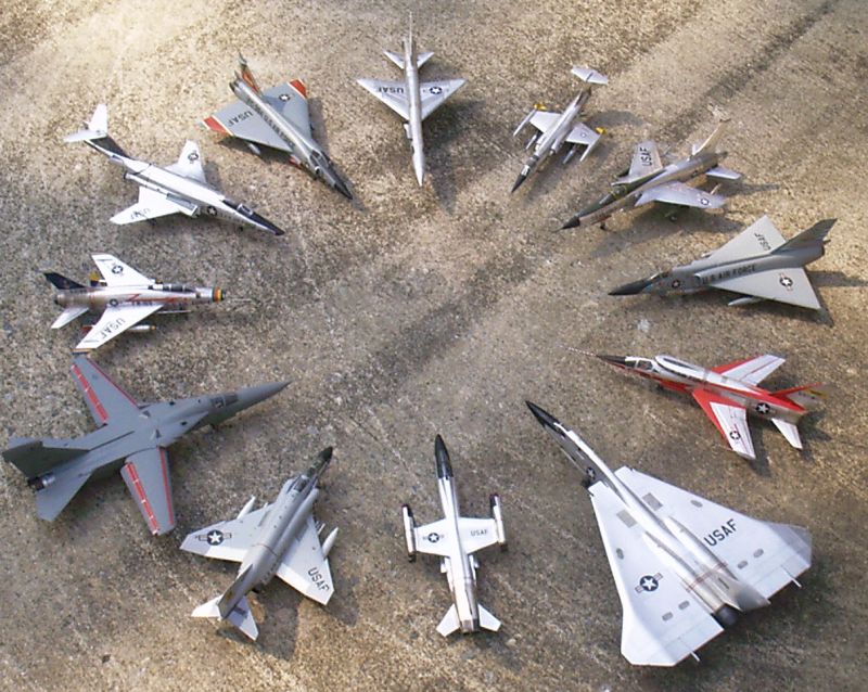
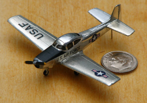
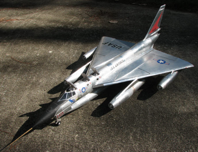
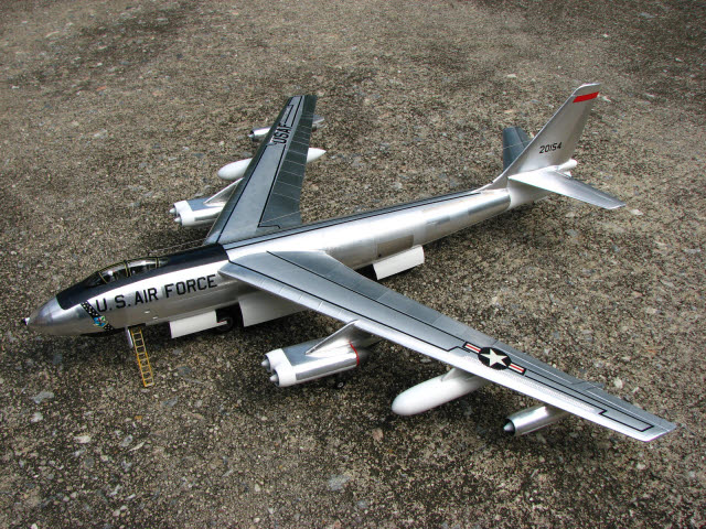
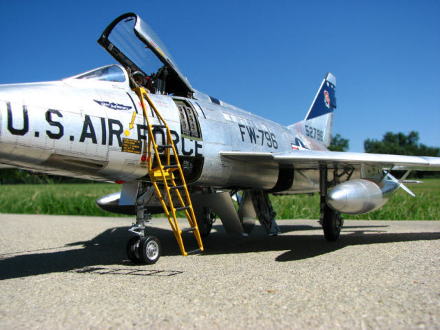
The number of folks who have tried foiling continues to increase. Foiling is not unique to any one scale; below are images of other foiled models I have done. The Navion is 1/144, the Century Series is 1/72, the P-51 is 1/32, the C-124 is 1/72, the B-47 is 1/72, the F-100 is 1/32, and the B-58 is a 1/32 scale PAPER model. Altogether I have over 30 models that are completely foiled, and many more that have foiled attributes. Foiling is infectious Guess I have "foil-itis" pretty bad...
I find foiling enjoyable and educational; after smoothing an entire model with the point of a toothpick, you would be surprised about how much more you know about your model and the plane it represents!
I hope this in some way helps those who want to try their hand at foiling, but are like a mosquito in a nudist colony; they know what to do, just not where to start...
© Ken Friend 2016
This article was published on Saturday, March 12 2016; Last modified on Tuesday, April 26 2016