
1/32 Canadair F-86 Sabre
By Mark Proulx
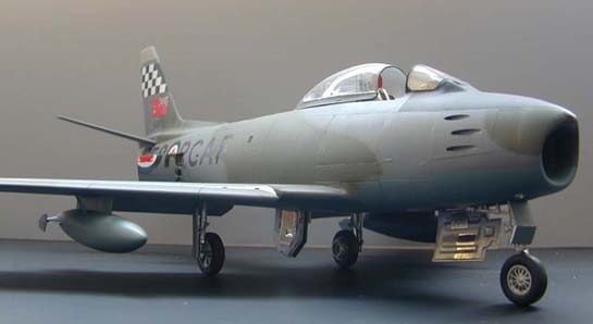
This article explains a relatively easy conversion of Hasegawa's F-86 Sabre into a Canadair Sabre 6. This kit has been released as an F-86F-40 in three different configurations in North America. The first release was by Minicraft/Hasegawa with markings supplied for a USAF Sabre and a South African Air Force aircraft. The second incarnation of this kit saw Hasegawa release it with kit decals supplied for the JASDF Aerobatic Team, The Blue Impulse. Included were decals to build any one of the teams aircraft. Team patches and stickers also came with the kit. The latest release has a JASDF F-86F-40 on the box art with decals supplied for that aircraft. I chose the latest release as the subject for this article.
First, some brief history as it pertains to the Sabre in Canadian service. Over 1815 Sabres of various marks were manufactured under license by Canadair in Montreal. The first flight of an F-86 Mark 1 took place on August 9, 1950. This was the sole Mark 1 Sabre and it still exists here at a museum in Edmonton, Canada.
Canadair Sabres went on to see service with a host of NATO countries in its post war service.
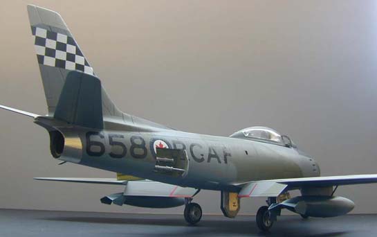
The subject of this article is a Sabre 6 flown by 441 Squadron RCAF in Europe in 1957. Using Larry Milberry's excellent reference, The Canadair Sabre, and a number of old IPMS newsletters I set out to work. Of course, the obvious change, is to back date this 6-3 wing into the Mark 6 variant. Scoops had to be added to the bottom and sides of the fuselage. The cockpit was poorly detailed and will have to be brought up to standard. Unfortunately, TAC Scale Dynamics had not released at the time of this conversion its excellent Sabre cockpit set. The nose wheel hub would also have to be changed. I also decided not to use the Eduard sets, preferring to do all scratchbuilding with plastic card.
Upon opening the box I found the kit to have very subtle raised detail, optional position leading edge slats, flaps, dive brakes and two different nose wheel hubs and drop tanks. While it is obviously not up to Hasegawa's 1/48 scale release I found the overall detail to be acceptable.
The first item of business was to sand off all surface detail and rescribe the aircraft. Using plans this was completed in short order. Now we progress from front to rear.
Cockpit
Firstly, it was decided that the seat in the kit sits to far forward and had to be moved aft by 1/4 inch. This would mean that the cockpit sidewalls and rear bulkhead would also need to be extended further aft by the corresponding amount. New side walls are made from .010 sheet styrene and added. Various knobs and dials are punched out of .010 sheet styrene using a Waldron Punch set. These items are than added to the sidewall consoles as per photo references. To finish boxing in the cockpit a new rear bulkhead was cut out of a sheet of .010 plastic and secured into place.
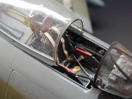
I felt that the kit supplied seat was a poor representation and would have to be redone. A new seat was scratchbuilt. The body of the seat was carved and sanded from resin. The sides of the seat are made from .010 sheet styrene. Armrests were added to the seat made from plastic strip. Seatbelts are then added made from paper cut to the proper width then slid into metal buckles from Reheat. Seat adjustment levers are added made from styrene rod. Plastruct channel was used to make up the ejection seat rails at the rear of the seat. Oxygen hose from Cutting Edge is the final item added to the seat.
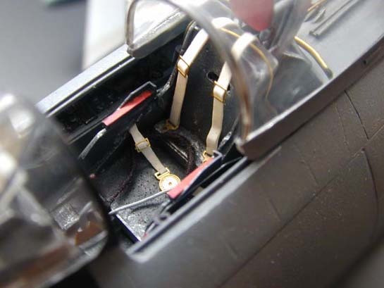
Map lights are also added to cockpit sidewalls. The harness that runs to these lights were coiled from wire and added to the cockpit. A shortcoming of almost every Sabre kit on the market is the area behind the seat. It seems like all manufacturers have this area entire upper deck area attached to the canopy. This is incorrect and all the rails should be attached to the fuselage. As per photos this was corrected using channel plastic from Plastruct. This now allows the canopy to slide on the rails as per the real aircraft. Details are added to rear deck and sliding portion of the canopy with bits of wire and sprue. Paint the cockpit dark grey to finish it off and scuff it up using Rub n' Buff and a silver pencil.
Fuselage
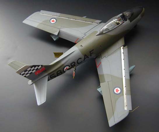
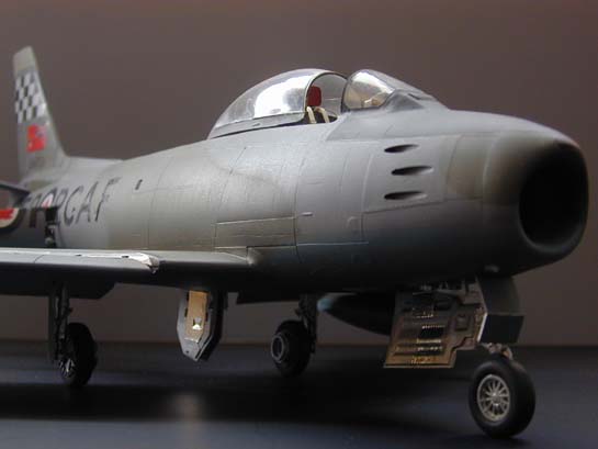
The fuselage was completed with the addition of two small scoops added to the underside of the fuselage just aft of the wing root. These are particular to the Canadair Sabre. These scoops were carved from a block of plastic. In addition, two vents were added to the sides of the fuselage at midpoint. Part # D 16 was sanded flush with the fuselage. The only modification used at the tail is the addition of brass tubing in the exhaust pipe. This effectively hides the prominent seam and will require the addition of weight in the nose. Gun access panels were glued shut. Optional position dive brakes are detailed and left open. Photo references confirmed these items are usually left open on the ground. Hydraulic lines running to the actuators was the plastic tubing supplied in the kit. Model railroad lenses fill in as landing lights.
Wings
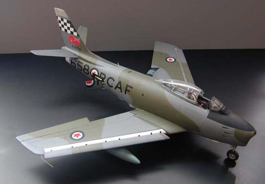
As explained earlier, this kit is marketed as an F-86F-40 with the 6-3 wing and extended wingtips. To make a Sabre 6 one must cut off the extended wingtips. Remove that portion outboard of the ailerons and add new wingtips. Now sand to shape and rescribe. Remember the ailerons now form the aft part of the wingtip and therefore the aileron hinge line is extended to the tip. The prominent step at the leading edge slat is flared into the top of the wing with liberal doses of putty for smooth air flow. The grooves in the leading edge of the wing should not extend as far back as they do and this area was corrected. I chose to add the 100 Imp. gal. tanks with optional fins made from .010 sheet styrene. The kit has optional position flaps that I chose to leave down. These items fit extremely well.
Landing Gear
The only real change to the landing gear is the nose gear. Drill out the molded in nose wheel hub and replace this item with the optional hub supplied in the kit. No mention is made of this item in the instructions but it is there. This is the proper unit to be used on the Sabre 6. While the drill bits were out, I thought I would go that little bit extra and add valve stems made from stretched sprue to each wheel assembly. Wheel wells are boxed in with plastic card. Of course,brake lines were also added made from wire.
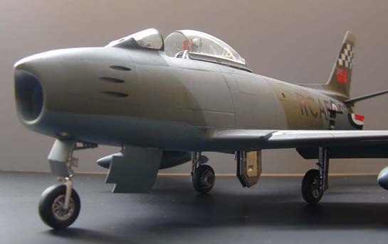
Finishing
The canopy is now polished with rubbing compound to allow better visibility of all the completed work. The kit was finished following instructions with no difficulty encountered. It fit together very well considering its age! A weight was added to the nose to assure proper stance. Make sure to spend a good amount of time filling in that seam that will be visible within the intake. The end result is worth it. I chose to glue the tail section to the model. This enables the seam to be filled and rescribed which more accurately represents the aircraft. The kit was then finished using Humbrol paints throughout. Bare Metal Foil serves as the polished aluminium area on the aft fuselage and leading edge of the wing. Decals came from Can Force, Arrow Graphics and the checkertail 441 Squadron marking is homemade. A piece of brass tubing is finally bent to shape to accurately represent the cranked pitot tube on the wingtip.
This completes my Sabre 6 conversion and I now have a 1/32 scale CF-104 in the works with Kendall's great detail sets. That should save a lot of work!
© Mark Proulx
This article was published on Wednesday, July 20 2011; Last modified on Saturday, May 14 2016