
21st Century Toys P-38J-15-LO “Lucky Lady” in 1/18 Scale – Part 4
By Jay Wheaton
Welcome back once again to the 1/18 scale Lucky Lady rebuild. It is a pretty long journey and we are not really that close yet! Last episode (part 3), we finished up the props and spinners. Now it is on to the cockpit and canopy, major sub-projects of their own each to consume many weeks of time. My aim was to produce an unprecedented cockpit with the advantage of large scale, and good research. I wanted no anachronisms or other errors – This was to be an ETO J-15LO cockpit. Some of you know “p38johnny” on LSP. I must say John Clements helped me immensely on the cockpit, and many other parts of the model where I just didn’t have enough information. Kudos to Johnny – I literally could not have done this without him.
The 21CT toy cockpit is not its worst feature but it is bad enough:
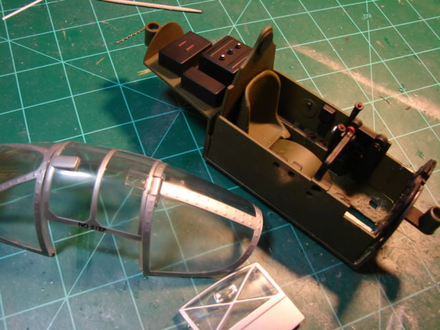
Everything would be replaced in the cockpit except the basic floor. The canopy on the other hand is indeed one its worst features:
Nice try 21CT, but wow what a misfire. It is hard to know where to begin describing all the inaccuracies. There were so many that I decided to take a bold path and scratch build the entire canopy except the hinged hatch which is compound curved and beyond my abilities. But that hatch would be heavily modified just to get it close. I had some experience scratch building a canopy – I successfully did it for the forward canopy of my 21CT P-51 rebuild Miss Velma, so I felt pretty good about it.
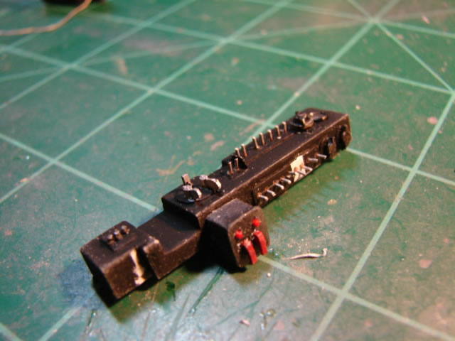
But first things first. Here is the heavily carved-on and Dremmelled-on cockpit floor and radio compartment:
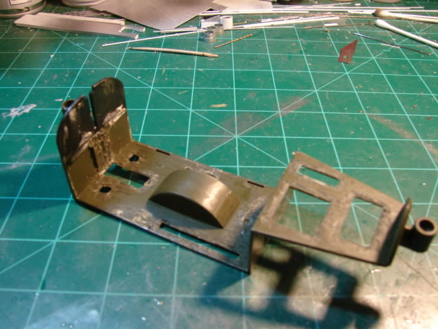
Note the circular bulge for the nose gear tire. In reality it is there, however not sharp cornered but more doughnut shaped – a shape I was unable to duplicate so I just used what I had. It gets pretty well covered up as you will see.
From there it was first making new side walls and other basic structural details, including the truss-stiffened wing center front spar which forms part of the cockpit:
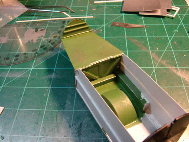
The sidewalls are just dry fitted here. I stiffened the hidden sides with rod stock but had to be careful to keep clearance to the sides of the fuselage. The radio compartment floor is in real life the wing center section upper skin – I attempted to make it look like that.
The first cockpit equipment details I worked were the hydraulic hand pump and reservoir, its hydraulic lines, and some heater ducting that exits the wing front spar and routes forward. Alas – in the end these items cannot be easily seen (why do we do this to ourselves?). Take a look:
The radio equipment for this aircraft required a bit of research to get right. Aftermarket radio equipment for P-38’s (for the Trumpeter kit for example) often is different; instead showing later period equipment or Pacific theater equipment. It’s actually pretty simple. All the ETO fighters in the 1944 timeframe of the war were equipped with a SCR-522 VHF radio and dynamotor set. Other stuff was taken out or was otherwise not provided, including the short range Detrola SCR-274 radio, which had with it a large floor mounted bracket and the familiar long wire aerial antenna that extends to the tail(s). I didn’t need to sweat that, nor does any P-38 modeler who does a P-38 around this timeframe. The radio equipment was mounted on a rack that also needed to be right, but that was Lockheed-provided so research was easier. Here is the scratch built finished product, ready for mounting to the radio compartment floor:
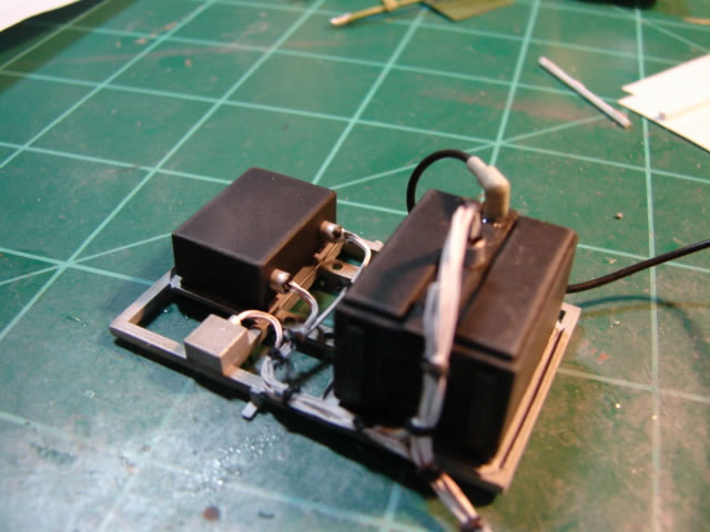
Radios are just scratch-built plastic sided boxes, but it took research to get them right. Wires are from multi-strand large gauge wire from the hardware store, and their runs also required research. This sub-assembly had to wait to be installed until the pilot armor plate was installed later on. Meanwhile, more scratch building was required. Here is the LH sidewall, and the unusual control “stick” or “wheel” specific to the P-38:
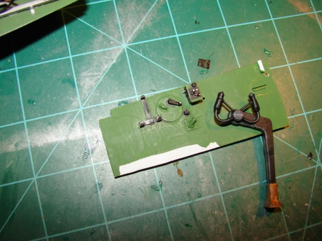
The stick was a very involved build using plastic rod and sheet stock, formed wire for the handle rings, and putty for the floor boot. It also has a home-made Lockheed emblem decal which doesn’t show up as well as I wanted. Note the sidewall has a black bracket for another piece of radio equipment which is absent. I have it on high authority that was indeed the case for J-15s in England. It also has on it a window crank and the bomb release panel. The RH sidewall is shown in just a couple more pictures.
The pilot seat was made of thin plastic sheet mostly, with flat pattern shapes modeled on the computer. Here it is freshly glued together:
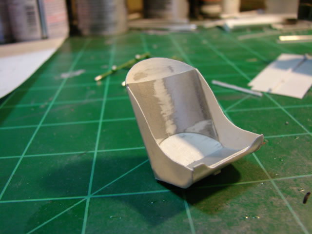
It has doubled up gauges which are actually armor plate for the pilot’s more valuable areas. The pilot armor plate was simply cut from plastic sheet, after careful measurement of scale drawings. At this point I could assemble some stuff:
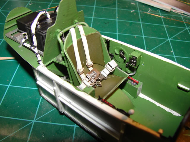
Lots of stuff here – the radio rack is attached to the floor and the armor plate. You can also see the seat is mounted to a tube frame made of carefully bent aluminum tubing with four little mount fittings. Seat belts were made from heavy gauge wine bottle foil and wire for the buckles.
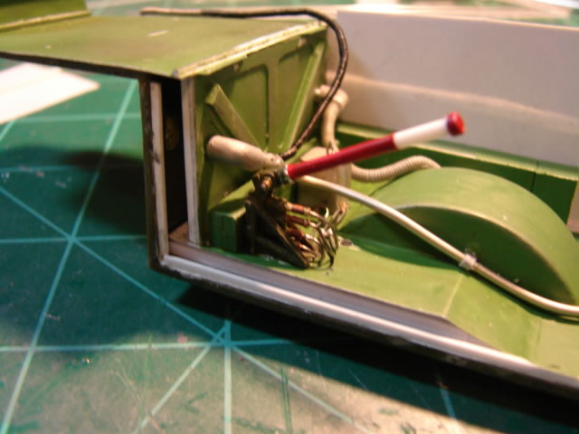
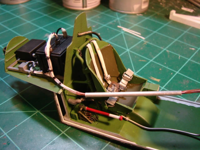
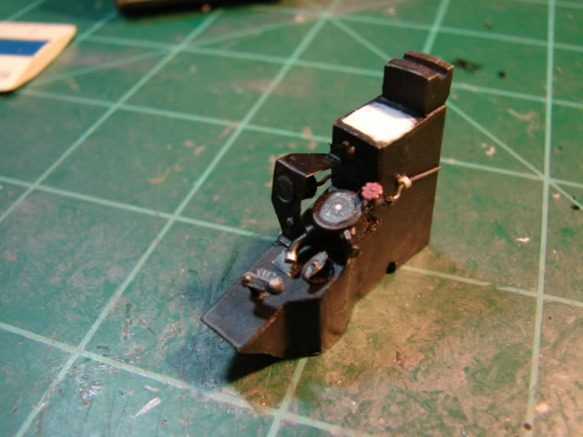
Take a look at the springs for seat height adjustment:
Those springs are made from solder and wrapped laboriously around a round tube and then the tube is extracted. Both those pictures also show the various heater tubes or hoses, including the spot heater, a hose that the pilot could hold by hand and point to something that needed to be heated up (like fingers?). It’s currently hooked around the armor plate but later will attach overhead on an aft canopy frame. And the wiring from the radios is there, waiting to be terminated further forward in the cockpit.
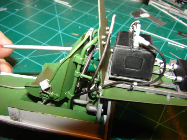
I want to show the RH sidewall, because it is busy and was a real challenge, mostly because of the wiring run from the radio equipment:
It is dry fitted here. You’ll see there another side window crank, the flap control quadrant, switch panels, and some equipment associated with the radios. And importantly you see a very difficult wire bundle.
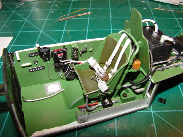
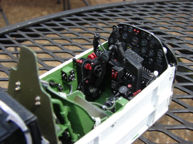
Add the sidewalls and here is how it looks:
Notice the red fuel control levers just to the left of the seat, and equipment behind the seat on trays (first aid kit and flare gun kit). Starting to look like a cockpit. But the busiest forward part remains. That big blank area on the LH sidewall is for the complex engine control stand which you will see presently.
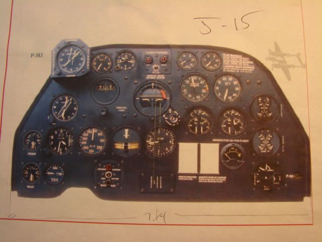
It was time for the instrument panel (IP). What a giant challenge. First I had to research which IP to model (there were various versions depending on the model). Here is the one for the J-15:
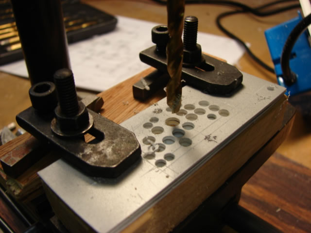
First, of course, was to model it on the computer. Then to cut out the panel from plastic sheet. From there, I sandwiched the fragile thin sheet between thicker sheet, scribed a pattern for hole drilling, and put it all on the end mill for drilling:
This is the end product IP panel detail:
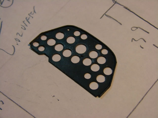
It has a periphery of thin rod stock, and of course black paint. This part may be more space than material, and was a major victory, and got me very fired up.
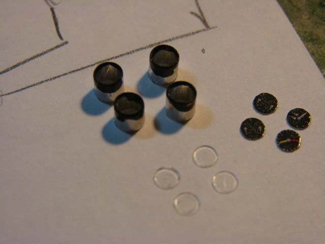
So how do I do the instruments themselves? Well, I stole the technique I developed for Miss Velma, which is to use aluminum tube, home-made decals, and punched clear plastic sheet. Here are the decals:
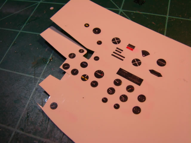
There are some other cockpit decals there as well.
And an assembly line of sorts for instruments:
The decals were left on their backing, and just cut out to match the ID of the alum tubes. Here are a couple of a finished instruments:
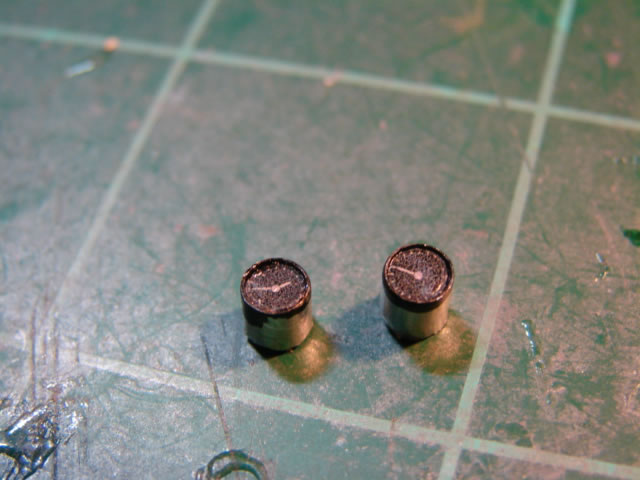
There would be twenty-two instruments for the IP, and a few more in other areas of the forward cockpit. A lot of work to say the least.
And here is the completed IP:
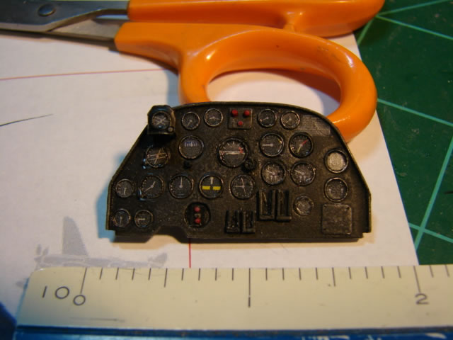
You will see soon that I left off the IP shroud, which was often done in the field, and because of that the IP is fairly easily seen through the canopy. That shroud is in real life fabric over some light frame, and would have been beyond my abilities to model. Anyway at this point I declared victory on the IP!
What is almost impossible to see are the rudder pedals:
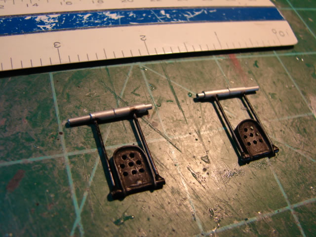
These components were too much trouble to go through to not be seen, and that’s all I’ll say about them!
This component however is easy to see – the engine control stand:

The assembly was made from multiple layers of plastic sheet in order to more easily provide the pie-shaped slots for the various levers to stick out of. The bracket low on the stand mounts yet another instrument, I think for oxygen.
Take a look at the front electrical switch panel:
It is just below the instrument panel. The silver switch levers are just chopped off pieces of wire. Really small stuff – needed high power magnification to do it all.
Last but not least was the center stand:
Where to start on this super complicated component. The structure was really tough to get right. I basically built a frame and “skinned” it with thin plastic sheet. It has on it the O2 regulator, O2 gage and its pesky bent-up bracket, engine choke lever, and rudder trim lever. It was a project on its own.
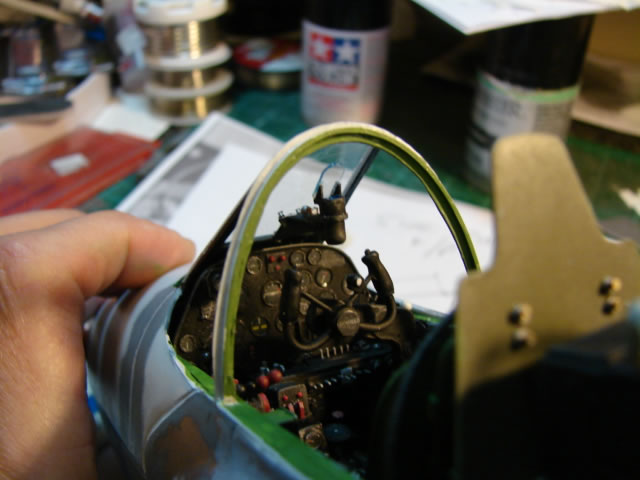
And then it was time to assemble it all:
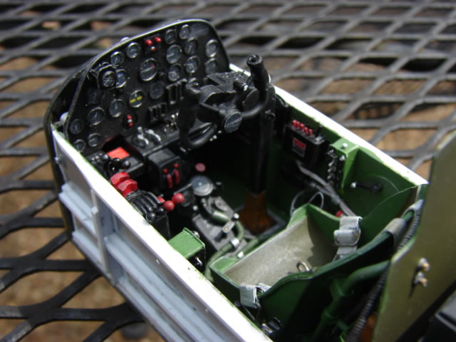
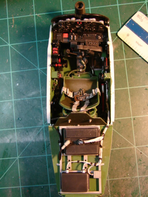
If it looks jam-packed you would be absolutely right! Getting in and out must have really been a process…..not to mention bailing out!
Around this point of the build, I was stressing about ballast weight. Any P-38 model is tail heavy and requires ballast weighting or a tail support, and this is certainly no exception. So I experimented with lead weights and the model dry assembled with landing gear and most all components present. These weights would be as far forward as possible – in the nose cone and right behind the propellers. And they needed to be epoxied in place prior to buttoning up the fuselage and booms of course. Take a look at the lead weights in the nose:
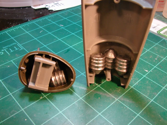
Those are civil war style mini-balls which I had around gathering dust. They did very nicely but made the model very heavy. The main landing gear however were plenty robust enough to handle it.
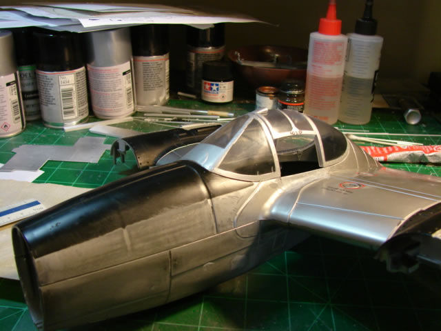
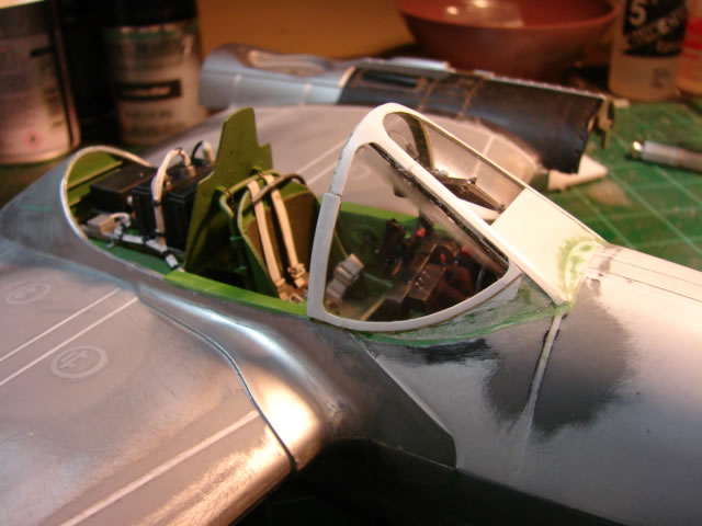
So now the forward canopy - another big project. And highly necessary if this P-38 was to look like it is supposed to. Here is the before shot in all its glory:
Yuck. OK what’s wrong with it… First the windshield has to be flat as a table which it is not. Second, the transition panel just forward of the windshield is basically missing (the little semi-circle raised portion is supposed to be it). Third, the aft frame is too far aft making the whole forward canopy too long. Fourth, the framing is wrong in various ways let’s say. And last, the side glass extends down too low, at least its forward portion. I would fix all of this. You can see scribe marks just forward of the windshield where the fun would begin.
Here is the fuselage pod after dremmelling away a good bit of it:
What the heck is he doing, you might ask. Well – the flat bullet-proof windscreen is at an extreme streamlined angle (more than the original windshield) and protrudes underneath the fuselage contour and terminates on a frame. I needed room for that to happen. And the side glass should be partly covered up with skin panel with the same contour as the glass (but different from the fuselage). I needed room for that too. Sounds confusing but you’ll see.
Here is the windshield detail. I made this out of thick gauge plastic (I think about .09 or .10 thick).
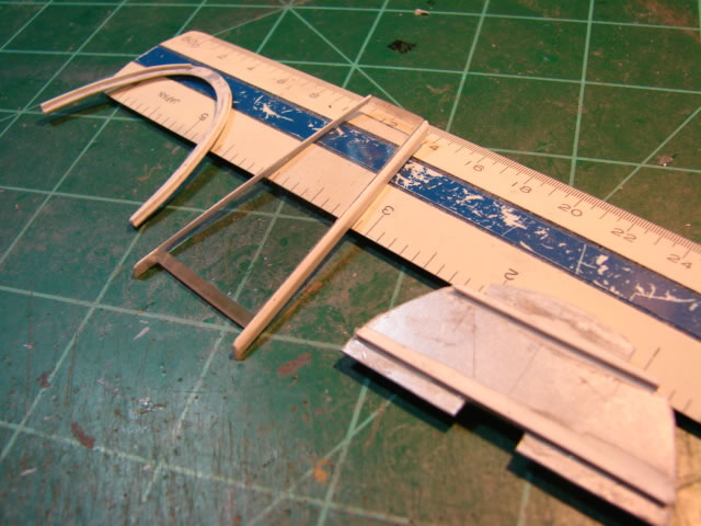
This simulates the bullet-proof plexiglass which in reality was 1.5 inches thick or so. It also has framing on each side made from simple rod stock. To its right is the forward fuselage frame where the windshield terminates on at its forward end under the fuselage contour. To its left is the canopy frame where the windshield terminates on at its aft upper end.
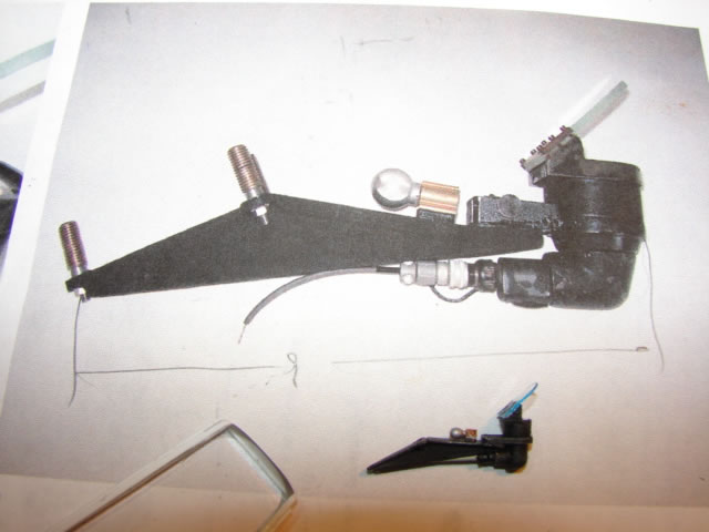
Before I could install the windshield though, the Lynn model L-3 gunsight had to be built up. This gunsight was mounted in a couple of different ways depending on the aircraft model. For the J-model at least, it was (amazingly) mounted directly to the windshield, bolted in three places.
Here is a shot of the real thing, with my modelled part:
Here it is closer up:
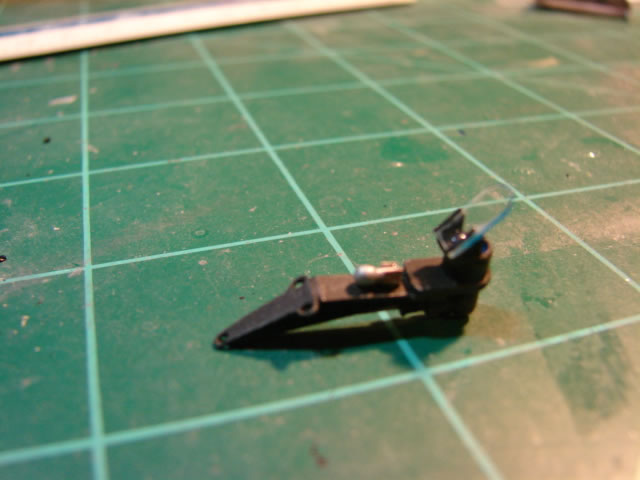
I even included the spare bulb. Was the gunsight and mounting bracket difficult to get right? You bet. They are very small.
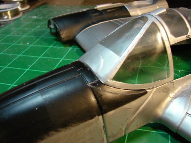
So now you should begin to see the method to the madness with the installed windshield (with gunsight):
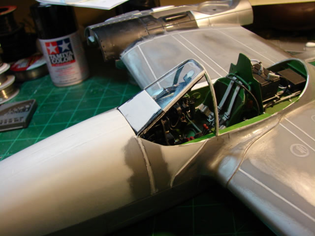
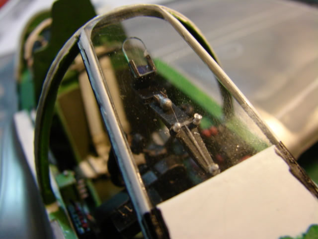
You can probably see how the windshield slips underneath the fuselage. There is a squarish panel covering the lower portion, and it will be filleted in to the fuselage contour. And of course you can see how the gunsight is bolted to the windshield. Curvature had to be sanded and filed into the top of the windshield. That is also the case on the actual aircraft. There was risk that this all would not end very well, but it all fit just fine after trimming here and filing there. Extensive computer modelling this area didn’t hurt either. MOF it was essential.
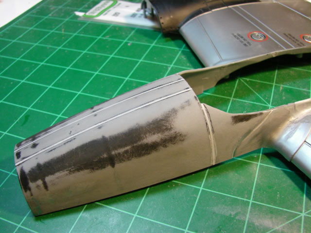
I then fabricated curved clear plastic side glass, rolling the .015 inch thick plastic sheet over wooden dowel to coax some curvature into each. Again – the flat pattern shape was generated on the computer. After that I cut out the framing strips which fortunately cover the raw edges of the glass parts (and the messy glue). And after installing them and puttying the transitions, it all looked like this:
And that is what it took to make that forward canopy look like a late model P-38.
Let’s take a breath. In the next part (part 5), I will show you what I did with the business end (the guns), the remainder of the canopy, and more. Thanks!
© Jay Wheaton 2016
This article was published on Friday, August 26 2016; Last modified on Friday, August 26 2016