
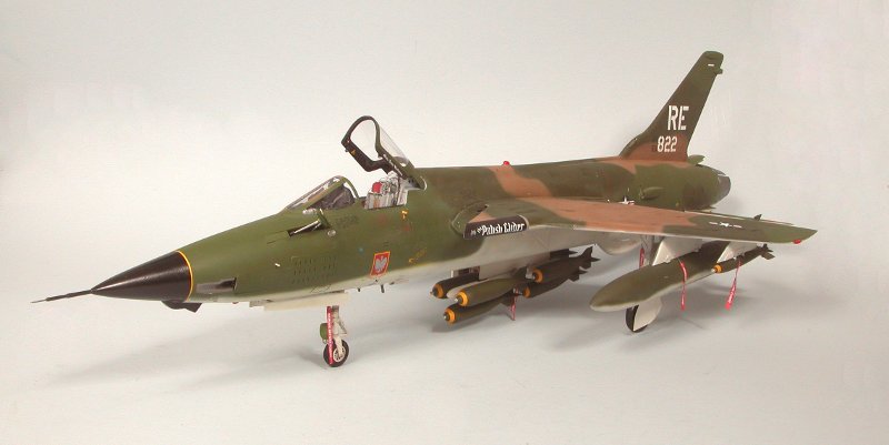
Trumpeter 1/32 F-105D Thunderchief
By Scott Murphy
Let's face it, Trumpeter’s Braille-scale THUD is a monster. The only model I have ever built that is larger than this one is Monogram’s behemoth 1/72 B-52D. One need only look at the size of the box to realize this one is going to take up quite a bit of shelf space. It contains over 500 pieces, more than a quarter of which are devoted strictly to armament. Two Bobs did the artwork for the decal sheet (printed by MicroScale) and it is gorgeous; I really see no need to look elsewhere for decals. Because of the size and weight of the finished model, I decided to replace the kit main struts with metal ones from Scale Aircraft Conversions. The castings are a little rough and are going to need some cleanup and polishing but the alternative would be a significant amount of strengthening to the kit pieces. One thing normally out of character for me is I am using the Black Box resin cockpit in lieu of rebuilding the very basic and generally inaccurate kit cockpit. I won it at a model contest raffle so it would be silly not to use it. It is literally a kit within a kit. In addition to replacing the kit cockpit, I did a significant amount of additional detailing to this model. Some was of my own choosing and some to correct deficiencies within the kit. I am very fortunate to have a 1:1 scale model of an F-105D just an hour's drive from the house at the USAF's Armament Museum onboard Eglin AFB. I took many reference photos there before beginning this project.
The Cockpit
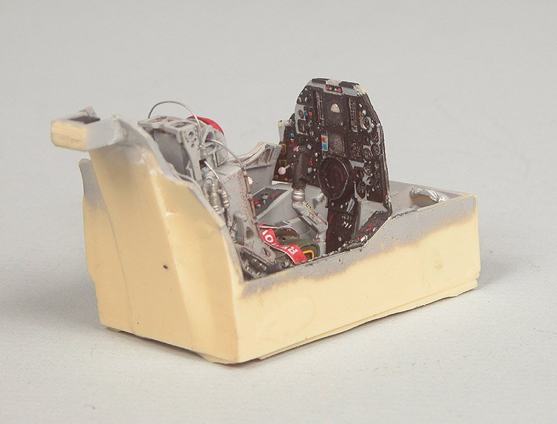
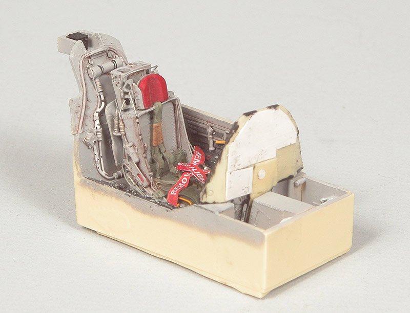
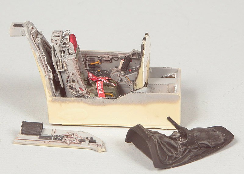
As is customary for me, and most modelers I am sure, I began with the cockpit. The Black Box cockpit contains some finest crafted pieces of resin I have ever seen. The seat is exquisite, as are the consoles, the instrument panel and the coaming. There are numerous undercuts, which are faithfully reproduced. If anything, it is overdone. Some of this beautiful detail is in places where it will never be seen once the 'pit is together. Assembly was quick and required minimal cleanup. Painting was far and away the most time consuming part of construction. I drilled out all the instrument faces on the instrument panel and placed some thin styrene sheet behind it. I then used the Waldron punch set and punched out the individual instruments from the kit piece of film and placed them in the resin panel, securing them with a little drop of Future™. The only exception was the ADI (Attitude Directional Indicator). The instrument on the resin panel was ball shaped, like it should be, so I left it in place and simply painted it. Since this particular instrument has a solid piece of glass in front of it, I cut a piece of 0.005" clear styrene to fit around it and secured it in place with some Future™. I made a similar piece to fit over the HSI (Horizontal Situation Indicator) just below it. I fashioned a lens from clear sprue and placed it in the instrument coaming to simulate the HUD (Head’s Up Display) optics.
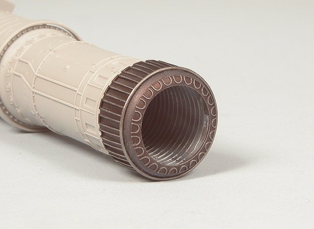
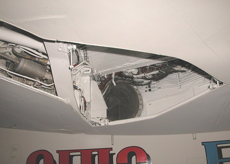
The J-75 Engine
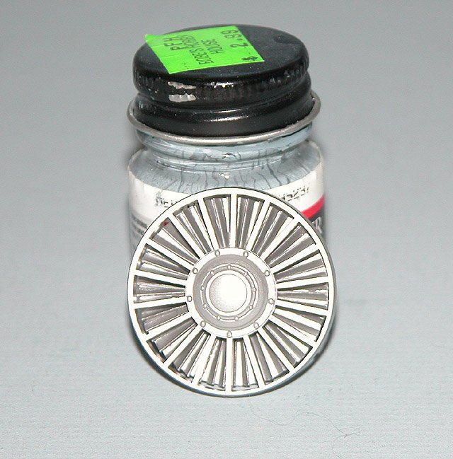
Standard fare for Trumpeter 1/32 jets is the inclusion of a nicely detailed engine. If one wishes to display it apart from the model it is certainly worthwhile taking the time and effort to detail it. That's the good news. The bad news is that for the most part, very little of will be visible when the model is together. For the most part, all it really does is add unnecessary weight, which must therefore be offset in the nose. This places undue strain on the landing gear, which are quite scale (and therefore kind of spindly) in their appearance. I originally thought about leaving it out entirely, keeping only the compressor and afterburning sections, however doing so would have made placement and alignment of those sections somewhat tricky. For that reason I went ahead and assembled it. For obvious reasons I was not concerned about seam cleanup or adding all the little details, which are numerous. Just the basic engine. The kit includes a piece to simulate the stator vanes and front of the starter assembly, but omitted to include anything behind it. This leaves a gaping black hole through the front of the engine. Therefore I scratchbuilt a first stage compressor section for it out of styrene. I cut out a disk from 0.010" sheet, just smaller than the diameter of the stator piece. I then added a piece of 0.375" styrene tube to the center. I cut a 0.125" wide strip of the sheet and cut it into small pieces. I split these pieces down the middle with an X-Acto ½" chisel, with one end roughly half the size of the other and glued them around the center tube at an approximate 60º angle . All in all it took 60 of these "blades" to cover the disk. The difference, however, was marked and in my opinion, worth the effort.
The afterburner area was somewhat of a disappointment. It comes in four pieces and is absolutely covered with ejector pins and sink marks. Cleanup of the marks was a time consuming process. Once the pieces were joined there were four significant seams, in spite of the fact I used a fairly liberal amount of medium thickness CA to put them together. I ran a bead of thin CA down the seam, which filled them reasonably well. They then had to then be repainted, which was difficult to do without overspraying the afterburner annulus. All in all I thought the finished result looked kind of poor but it was about all that can be done under the circumstances. If ever there was a place for a seamless resin piece it's here.
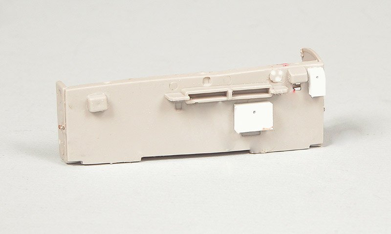
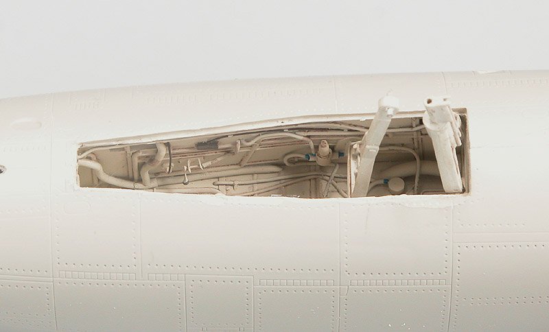
The Nosewheel Well
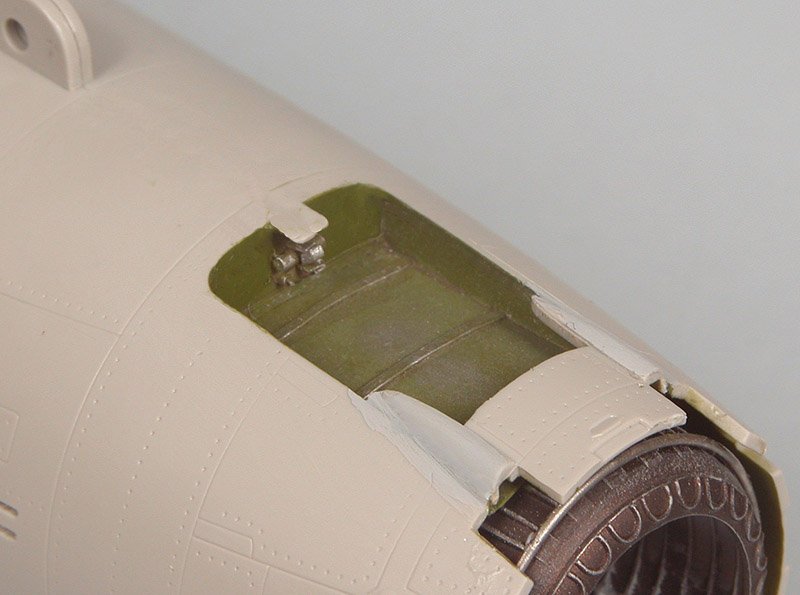
The nosewheel well area needed a lot of work. Detail was lacking, and in many cases, inaccurate. Fortunately, the nosewheel well comes in five pieces so it was easy to detail. Solder, wire, styrene rod, strip and sheet and lead foil rounded out the necessary materials. Because of the way they are constructed, the mainwheel wells will have to be detailed once they are put together. Like the nosewheel well, detail was very poor so I pretty much wiped them slick and completely redid them. More on them later.
The Kit Nose Strut
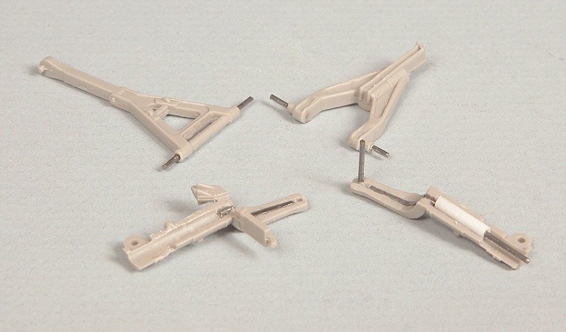
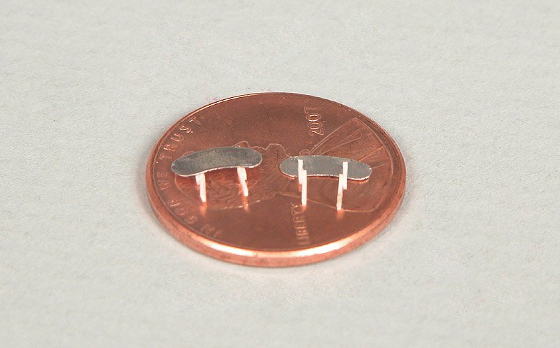
As I mentioned previously, this is going to be a very heavy model. The instructions call for 110 grams (3.88 oz.) of weight in the nose to offset the tail. That is a lot of weight! Subsequently, there is going to be a lot of stress on the nose strut to support all this weight. When I got my white metal main struts there was no nose strut included. They are now available but it was not practical to get an entire set of three struts just for the nose strut. To that end, I decided to beef up the kit pieces with steel pins. I have a supply (though dwindling, admittedly) of 0.030" steel pins from an old contour gauge that are perfect for the job. I first CA'd a piece of 0.125 x 0.25" styrene block in two places to the outside of the nosewheel well sides to serve as a reinforcing block. Overkill perhaps, but it will be more than adequately strong. It is much better to err on the side of caution. I ground a channel into the nose strut halves using a 0.033" carbide drill bit and bent a piece of the 0.030"wire to fit inside of it. I used liberal amounts of CA to affix it in place and then ground any bits protruding above the channel flush with a Dremel cut-off wheel. This significantly strengthened the strut at it's weakest points. Likewise, I reinforced all attachment points for the other nose strut pieces with steel pins where they will insert through holes drilled in the styrene reinforcing blocks. I did not have any metal rod or tube of appropriate size handy for the inside of the strut so I did the next best thing; I strengthened a piece of 0.080" styrene rod with a steel pin and inserted that into the strut (lower right in the photograph). The pin extends past the styrene to mate with the top half of the strut, adding rigidity to the entire structure. This little project was good for close to two hours worth of work however the benefits gained far outweigh the time required. This strut will neither break nor deform under load for any foreseeable amount of time.
The Radome
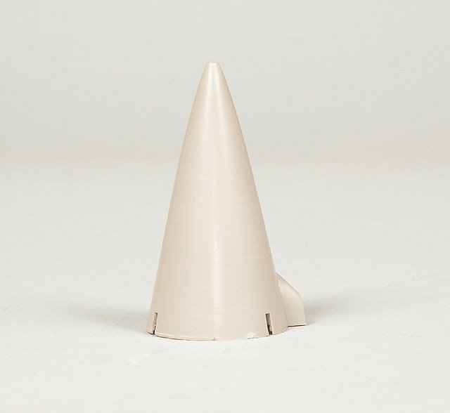
Like pretty much every other model manufacturer who has produced an F-105 Thunderchief kit, Trumpeter contoured the radome incorrectly. When placed against a scaled up photo of the real thing (I am generally distrustful of drawings unless they are from the manufacturer), the kit piece is too long and way too "pointy". The kit piece looks like something that should be on the front of a MiG-21 instead of a Thunderchief. Absent was the noticeable ogival curve to the tip of it. I used the razor saw and cut off the top 4mm or so and reshaped it using the Dremel and a grinding bit, files and sandpaper. Fortunately the tip of the radome was of sufficiently thick plastic that I did not have to add any styrene, just some CA at the very tip. The difference is very noticeable. The tail and rudder also have some shape issues as well and will have to be dealt with in time.
The Canopy and Windscreen
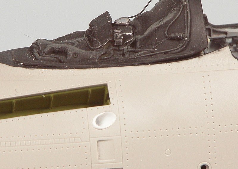
Like the rest of the kit, the clear parts are very large. Areas of the canopy and windscreen that would be occupied by framework are lightly frosted, which does make it easier to distinguish demarcation lines. Both the canopy and windscreen were totally void of any details. Since there was a fair amount of structure on both, the canopy especially, I constructed it from reference photos using styrene, solder, wire and soda can aluminum. All in all I added about 60 pieces to the windscreen and canopy. I added a control box and wet compass to the windscreen along with a few bits of styrene for framing details. I inserted a Waldron instrument in the wet compass after it was painted. A reasonable amount of detailing has made a significant improvement in a very visible part of the model!
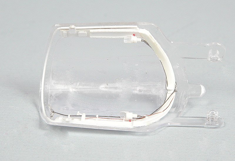
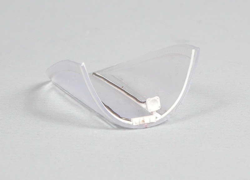
The kit did not come with any mirrors for the front canopy bow (there are two) so I cut some out of soda can aluminum, removed the paint on one side (leaving the plastic coating on the other because CA adheres to it a lot better than to the bare metal), with 0000 steel wool and then polished it with the Dremel and some Turtle Wax Clearcoat polish. With reasonable care aluminum can be polished to a near-mirror like finish. I made the attachment points out of some 0.010" x 0.020" styrene strip. They will be attached to the windscreen right before it is installed because they are very fragile!
The Drag Chute Compartment
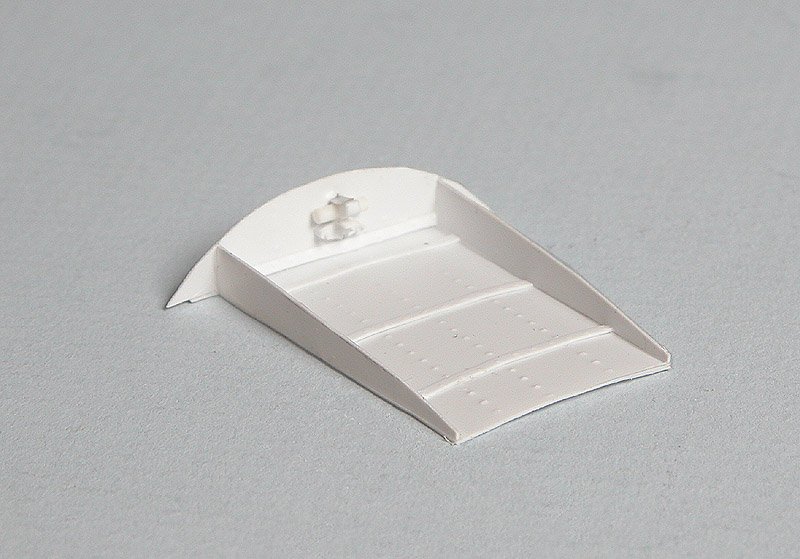
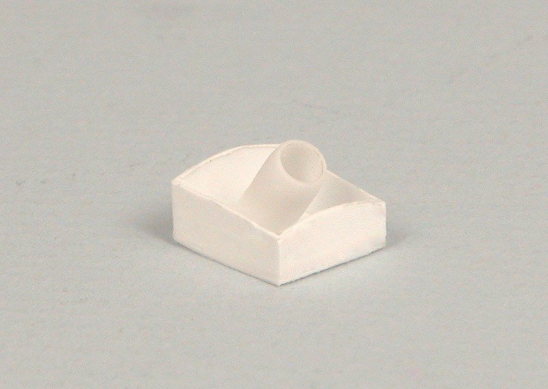
I found several photos of THUDS sitting on the ramp or in revetments with their drag chute doors open so I decided to leave mine open as well. If nothing else it adds a little bit of interest to the tail section. Trumpeter does allow this option and they did a good job of detailing the door. However, no provision was made to close off the bay. If left uncorrected you will be looking directly at the top of the engine, which was clearly not the case. There was no way you could lay a nylon parachute pack on top of the afterburning section of an engine without it melting into a pile of goo. I used a contour gauge to get the shape of the interior and built a box to go around the opening. I only had one photo of the insides of it so I did the best I could to detail it. Granted, from the photos there was not a lot of structure on the inside of the compartment. I made raised rivets by turning the styrene over and running a ponce wheel over it to make raised impressions. Simple but effective. When all was said and done, the improvement was well worth the effort.
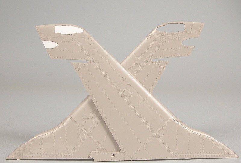
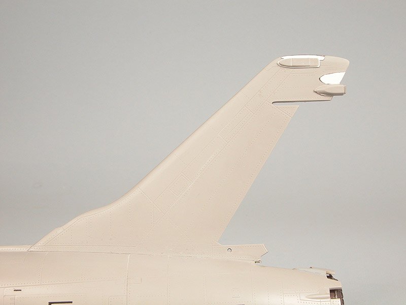
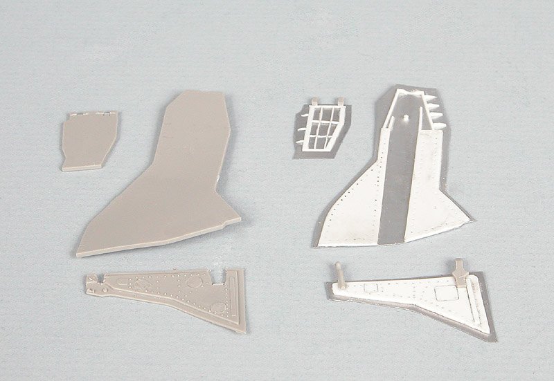
At this point I joined the fuselage halves. Fit between the halves for the most part was very good; not a lot of seam cleanup was required. A fair amount of touch-up rescribing and redrilling of rivets was necessary because this model has a lot of panel lines and rivets. Next up was to address the incorrect shape of the vertical tail. I am not sure if Trumpeter just made an error in the shape or if they actually did the tail in the larger configuration present on the F-105G two seater. Regardless, it was incorrect and really should be corrected. I believe there is a resin correction set out but I would rather do it myself in a few hours than plunk down $20 for someone else’s work.
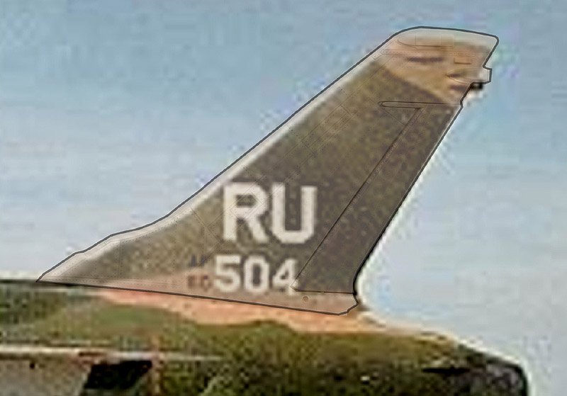
Before I took the razor saw to it I searched the web to find a photo of a THUD from an exact side planform view. It took a good bit of searching but I finally found one that fit the bill. I photographed the kit tail, still on the sprue (though I taped the rudder in place) and cut it out in Adobe Photoshop. I outlined it with a fine black line and increased its transparency. I then superimposed it over the photo of the real thing. I immediately noticed that the kit tail was too tall and that the ECM fairings were in the wrong place. Any slight differences in shot angle of the two photos would not account for the height and location differences. Lowering the top of the tail will be a pretty easy task. Moving the ECM antenna fairings are going to take a lot more work. The first thing I did was to cut out the four ECM fairings with a #80 carbide drill bit in my battery operated Dremel (because it turns at a slower speed than the lowest setting on my AC one), using great care not to break the bit. They are so sharp that they really work the best for cutting out small parts. I then cut pieces of 0.030" thick styrene sheet using the holes as templates and filled them in, using CA to fill any gaps. The pieces were then sanded smooth with files and sandpaper and polished with 0000 steel wool. Next up was to take the razor saw and remove the top .18' or so from the tail and reshape the top contour to match the photo. The top of the fin was filled with CA and the ECM antenna fairings replaced in their correct locations. With the tail modifications finally completed, it becomes apparent how far off the kit pieces were, the lower antenna especially. Was it worth 4 hours of work to correct it? Most people might say no but I figured if I am going to correct other glaring errors in this model (the radome and drag chute compartment to name just two) I may as well do all of them
The Combat Camera
The kit includes the fairing just behind the radome for the combat camera but once again there is nothing inside, leaving yet another Trumpeter signature black hole. I used my contour gage to get the curvatures correct and constructed a box out of sheet styrene. I then made a lens out of styrene tube and clear sprue. In this scale it would be noticeable that there is nothing behind the "glass". Since most combat footage was filmed in black and white, a yellow filter was usually mounted in front of the lens to increase contrast. I added this by painting a piece of clear styrene clear yellow and punched it out using the Waldron punch set. I affixed it to the front of the lens with some Future™. Sometimes it’s the little details that make all the difference!
The Wings
Before I could start putting the wings together I had to accomplish several tasks. First off was to fill in several very large (0.20") ejector pin marks in the intakes. Additionally, there is a rather pronounced (0.050") step on the fuselage intake area that lies barely 1/2" inside the intake. I took the Dremel and a grinding bit and ground away the step, tapering it to a knife edge so it would not be as noticeable once the wings are in place. When the wings and fuselage are joined it will give the impression of a continuous surface.
Wing construction was fairly straightforward. The kit also provides separate spoilers so they can be positioned either up or down. The only time spoilers would be extended is if the aircraft were on rollout (to shorten landing distance) or maintenance was being performed on them. Therefore I decided to display them in the stowed position. The fit was less than perfect, , necessitating that each piece be individually fitted. There was also a pretty nasty seam on the inside of the intake when the wings were joined but some filling with CA and filing and sanding fixed it. The fact that the area is easily accessible before the wings are joined to the fuselage made this an easy task.
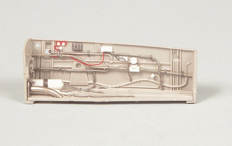
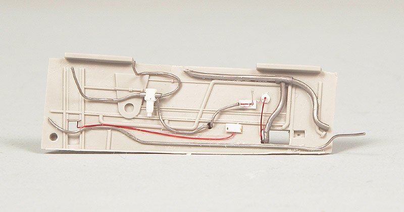
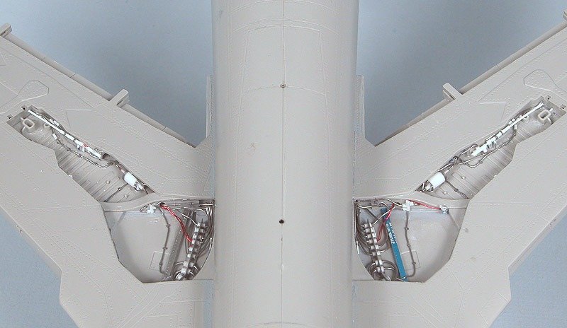
The Main Wheel Wells
With all that behind me, I could now concentrate on detailing the main wheel well. Detail in the kit wheel wells was very sparse to I ground everything smooth with the Dremel and a shaping bit and started over from scratch. It is fictitious in most places and very sparse to non-existent in others. THUD wheel wells, like most modern jets, are a pretty busy places filled with wires, cables, actuators, hydraulic and oil lines, etc. I do believe someone makes a set of resin wheel well inserts for this model. Unless you are a glutton for scratchbuilding punishment like I am, I would strongly suggest you invest in them. The scratchbuilt wheel wells are constructed of wire, solder, soda can aluminum, stainless steel screening, lead foil, styrene sheet, rod, tube and strip. I added a soda can insert to one side of the wheel well so I could add raised rivets. It is reasonably easy to work and if you glue the side that has the plastic liner to the styrene it adheres very tightly using CA. It took about 14 hours to complete just one well but the finished result was definitely worth the work.
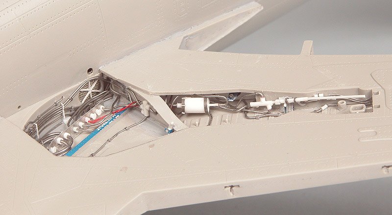
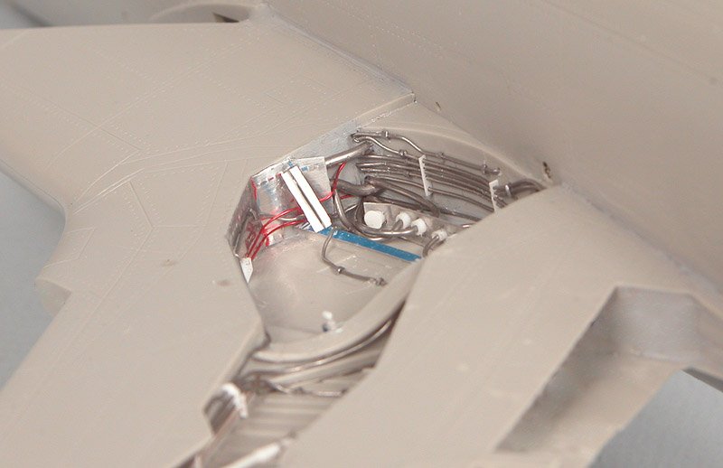
With the wheel wells complete one can see that the extra work put into this area has paid great dividends in realism. Granted, a lot of the detail I added could not be convincingly molded because of the undercuts and other limitations of the injection molding process.
The Main Landing Gear Doors
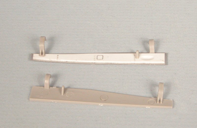
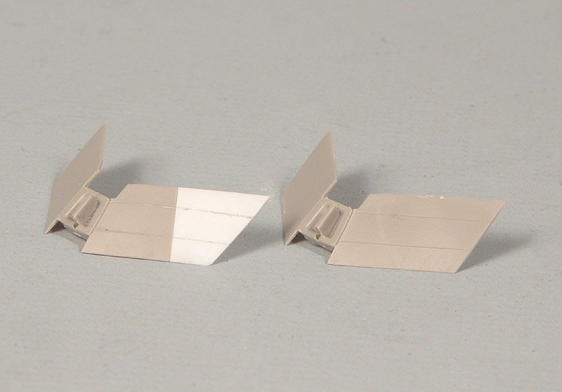
The landing gear doors are going to also needed to be re-done. The kit pieces are very thick and, in the case of the main doors, totally void of detail. I used the kit pieces as templates and cut out new pieces from soda can aluminum. The only things I saved from the kit doors were the hinges. I added styrene sheet and rod and tube to add detail to all the doors. As the photo shows, the difference before and after is quite noticeable. At this point I could finally see the light at the end of the scratchbuilding tunnel!
The Nose Landing Gear Doors
Like the main doors, the nosegear doors were very thick and void of detail. They also had some pretty nasty ejector pin marks. Once again I traced their outline onto soda can aluminum and added sheet styrene to form the inner body of the door. Like the mains, I kept the kit hinges but that was it.
Odds and Ends
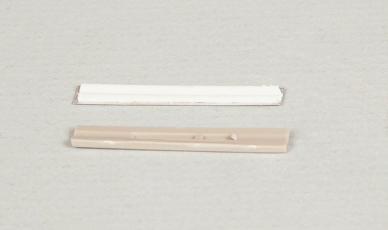
There are a few other things that needed attention before I start on the ordnance. First were the doors for the inflight refueling probe. Like all the other doors in this kit, they were extremely thick and completely lacking in detail. As before, I used the kit piece as a template and cut out a new one of soda can aluminum and with some sheet styrene for the center of the door. I used a file to make a groove down the middle of the door where it will mate with the probe. There is a second door, forward of the main one that closed after the probe was extended. All that needed to be done on that one was thin the edge that would be visible, no point in doing more work than is necessary.
Jets have numerous drains along the underside of the fuselage, especially around the engine. Using reference photos, I drilled several 0.027" holes and inserted pieces of 0.025" rod with a 0.0135" hole drilled in the end. The fuel dump mast had a basically solid end to it so I drilled it out and inserted four pieces of 0.010" wire through the side of it. Sometimes it's the little details!
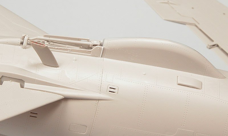
There is a large vent on the port side of the fuselage just below and aft of the inflight refueling probe bay. In the model it is simply depicted as an oval depression. On the real thing there is a definite hole there. I ground out the oval with a Dremel and grinding bit and inserted a piece of styrene tube into the hole. I thinned the edges to near scale thickness with a round file. I also ground out the cooling slots in the door covering the M-61 20mm Gatling gun with a 0.020" carbide drill bit.
External Stores and Ordnance
Trumpeter provides the modeler with a vast array of ordnance for the THUD. Iron bombs, Shrike Anti-Radiation Missiles (ARM), Bullpup air to ground missiles and napalm canisters. Most of them will not be used so in the spares box they go. They also provided external fuel tanks for both the wings and the internal bomb bay (which you cannot see unless you left the bomb bad doors open.
The first thing I noticed when I started looking at the external fuel tanks and armament was part of one of the drop tank fins had been torn in half. The broken piece was not in the sealed bag so I had to fix it with some styrene sheet. Unlike so many models that depict fins on drop tanks as thick, rectangular cross section slabs, Trumpeter actually made these very thin and tapered, a nice touch. I cut off the bad part of the fin with a Dremel circular saw and added a piece of 0.025" styrene sheet, adding the taper with a Dremel shaping bit and files. A little bit of rescribing and all fixed!
I chose to add only iron bombs on this model; six (6) M117 750 pound bombs on a Multiple Ejector Rack (MER) on the centerline and a single Mk82 500 pound bomb on the outboard stations. The standard fuses included in the kit were grossly inadequate but the extended fuses were correct, so. I cut off the tips of the extended fuses and inserted them into the bombs. The small bar propellers on the fuses were poorly depicted so I cut them off, made a slit in the fuse with the Dremel and a ½” circular saw and inserted a piece of soda can aluminum, which I twisted with a pair of forceps.
Remaining Construction
As is often the case for mammoth projects like this, the actual construction of the kit is anti-climatic given the amount of detailing that I did. For the most part, the remainder of the construction went without a hitch. Trumpeter does provide a lot of little details that are a nice touch. Fit around the radome was not that great and required a lot of filling. Given the fact that they provided a radar (though one quite lacking in detail and inaccurate in may respects) I suspect that they expected the radome to be in the open position so perfect fit was not critical. Fit likewise was very poor around the windscreen and required a fair amount of filling, filing and sanding to get a smooth transition. Even though I used white metal main landing gear in lieu of the kit pieces, I still drilled a hole in the top of the metal gear and inserted a 0.030” steel pin. I drilled another hole all the way through the wing and simply ground the top of the pin flat with the top of the wing. This provided an added measure of strength to gear that will have to bear a lot of weight and potential sideways movement. There were still a lot of ejector pin marks that had to be fixed especially on the four sections forming the tailpipe. I left the bottom one open as it also served as a speed brake. Many photos I found of THUDS on the ramp had the inflight refueling probe extended on the ground so I followed suit with mine.
Painting and Decaling
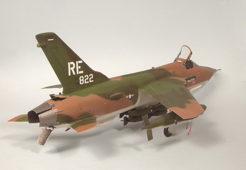
I painted the model with Testors Model Master solvent-based enamels, standard fare with me. I used the standard SEA (South East Asia) color scheme. Colors for the top surfaces were Dark Tan (FS30219), Medium Green (FS34102) and Dark Green (FS34079). Although the undersides in photos appear to be white, they are actually painted Camouflage Gray (FS36622). Testors’ Camouflage Gray looked dark to me so I lightened it as well with about 33% flat white. When juxtaposed against the darker upper side colors, it did appear to almost be white. Prior to painting, I sprayed the model with automotive primer from a rattle can. It was especially important that the metal main gear be primed prior to painting so the paint would adhere properly. I pre-shaded the major panel lines with flat black. Because this model is so large, I switched to the heavy-duty needle and head on my Badger 150 to paint the individual colors. I then changed back to the fine head and needle and tightened up the demarcation lines. The ordnance was so large it would not fit in the chuck of my 3/8” drill so I could paint the yellow bands on them. I would up just having to paint them freehand, which was somewhat of a time consuming process.
I covered the model in a couple of coats of Future™. The decals provided in the kit were so well done I decided to use them. The carrier film was extremely thin, becoming almost totally invisible once the decals were dry. Once they were dry, I flattened the finish with Testors Dullcote™.
I finished things off with some “REMOVE BEFORE FLIGHT” flags made on the computer and some light weathering with pastels.
Summary
I added quite a bit of detail to this model. As projects go, this one still went fairly quickly; I only spent about 300 hours from start to finish. All in all, I am happy with the end result. My greatest concern is where I am going to find enough shelf space to adequately display this beast!
© Scott Murphy 2009
This article was published on Wednesday, July 20 2011; Last modified on Saturday, May 14 2016