
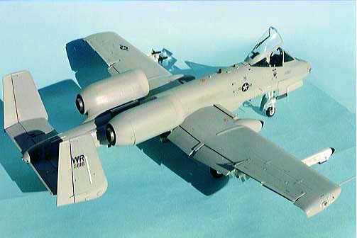
Trumpeter A-10
By Ted Taylor
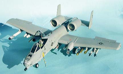
The 1/32nd scale A-10 from Trumpeter (a relatively new Chinese manufacturer) comes in such a large well packed box that no modeller can fail to be impressed by it with metal and resin parts, crystal clear canopy and windshield etc. etc. On closer inspection things are not all they seem to be, it seems Trumpeter could not make up their mind as to which version to build. There are three basic versions of the A-10, an early production one, a later version with the LASTE fit (recognize these with the formation light strips), and even later version with the GSP dome mounted on top of the fuselage. The kit comes with a bit of each on board so you will have to make up your mind early on which markings you will want and adjust the kit accordingly. If you want an early basic machine then you will need to remove the LASTE sensors from the outsides of the fins. Then you will have to remove the GSP dome and fill the resultant holes.
If you want the LASTE fit version then you will need to add the Light strips on the fins, wing tips, top of the fuselage and two below the tail plus add the rest of the sensors under the tailplanes and again remove the dome but retain it if you want the very latest version. It will all depend on your markings but remember the LASTE fit came after the Gulf war, so don’t be tempted.
The kit can be built up straight from the box into a nice looking model but it will not be very accurate and this shows at this scale.
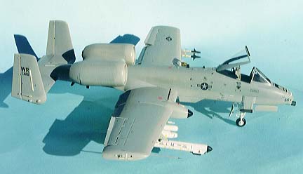
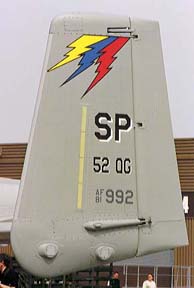
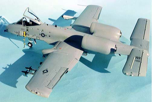
The kit markings are for two lizard scheme aircraft but I wanted a ghost grey scheme that was painted on the RAF Bentwaters aircraft when they went in to have the LASTE upgrades fitted.
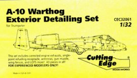
I had the Cutting Edge super detail sets in for review and so I have incorporated these into this review.
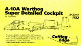
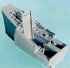
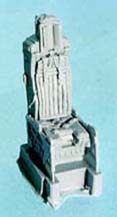
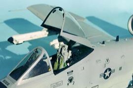
The cockpit set CEC32057 has a new well-detailed bathtub, instrument panel and coaming, stick, HUD frames and a beautiful ACES II seat that is the best I have seen from anyone. There are some interior frames for the canopy and a correct operating system to open it with.
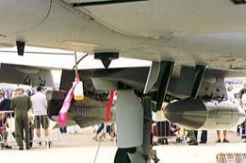
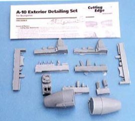
The exterior set CEC32061 has replacement exhausts, all the LASTE sensors, refueling point and door, replacement chaff dispensers for the sponsons etc., various apu exhausts and intakes for the rear of the fuselage, a number of antennas plus a new, more realistic, cannon muzzle with lightning holes and separate barrels. There are some other small items (43 in all), which are all explained on the instruction sheet that comes with the set.
Construction Notes
My starting point was with the rear fuselage halves where I drilled out the hole to take the APU exhaust, make it a tight fit, just enough to let the resin part slide through, make it flush with the outer skin and run a bead of superglue around the inside edge. Note the positions of the other items and drill the appropriate size hole then repeat the procedure with the remaining parts. The rear halves were now cemented and left to harden before cutting out the centreline vent on the underside and cementing in the replacement resin part.
The fit of some parts is not good, there are quite a few gaps to fill but worst of all are the mating surfaces themselves, most have tiny blobs of plastic which stop the two surfaces actually touching and I found I had to clean up nearly all the edges before attempting to glue them.
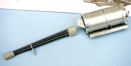
The gun is a little masterpiece with separate barrels, breach and ammo drum, it is a shame you don’t see it when the fuselage halves are closed up. You need to put 80gms of ballast in the drum or you will have a tail sitter but there is a clear plastic prop provided on the canopy sprue, if you are using the replacement resin set then you can make the whole gun up as a separate display but don’t forget the ballast.
The kit cockpit is, to say the least, basic although the seat isn’t bad but you will need to add some belts, and the stick is beyond belief so I used the resin set.
The pour block on the base of the bathtub will need cutting away slightly to allow the wheel bay to seat properly but not too much as you need all the weight you can get up front. You have a choice when making up the instrument panel, you can sandwich a clear film between two resin sections or you can just use the main panel and paint and highlight the instrument faces, which I did. Now tape the front halves together and, using the template supplied, cut out the coaming ready to take the new corrected resin part, get a snug fit by cutting a little at a time.
The new cockpit comes with the rear turtle deck moulded as one, this ensures perfect alignment and ease of fixing when the whole is mounted in the fuselage and the halves cemented. Don't just glue it to one side and leave it for it is bound to be at the wrong angle (Murphy's law) get the other half in position quickly before the cement hardens and leave to harden, my next step was when this assembly had hardened, the hole for the gun muzzle was reamed out with a round Arbrafile until the new resin part was a tight fit.
This is the time when you need to decide if you want the GSP dome, if not cement a piece of scrap 15 thou plasticard beneath the mounting hole ready to take filler later. Fit the wheel bay and join the two halves of the fuselage, allow to harden and add filler where needed, (I flooded the join with liquid poly and waited a few seconds then squeezed the halves together and enough molten plastic oozed out to form its own filler).
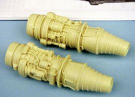
The kit provides you with resin engines, which look very attractive in the box and is probably what has sold a number of the kits, they are not really accurate and are encased in clear plastic “bubbles” for want of a better word. The real engines have a short front outer shell and a large exhaust cover so I suppose you could cut the plastic bubble into front and rear sections as a compromise if you wanted to use the operating engine doors in the open position.
The wings have separate flaps, which slide in or out so make up all the flaps (the port inners are numbered 3&5 not 4&6) and fill the joins on the lower surfaces. Whilst these harden off, clean up the inner surfaces of the wing tip joins or they will not seat properly (you will still need filler later), then clear out the hinge recesses for the speed brakes and generally tidy the area up including the hinge pins on the brakes them selves, this should make for smoother movements when fitted in.
Once you are happy with the flaps add the runners one at a time with each flap, add the spars N3and N4 then the lower wing halves.
There is no positive location for the inner rear edge of each wing and later I found I had to trim some of the locating tabs down before the wings would fit the fuselage and conform to the fairing shape even then I needed lots of filler on the underside join.
Carefully add the control rod and mass balance to the speed brakes and gently push the hinge pins home into the spars, I have left mine loose to show their potential but remember these are not the ailerons, the drawings would have you believe the aileron hinge line is further forward but in real life the line is closer to the brake line and not quite where the kit has them inscribed.
Next I cut the sponsons parts as directed and added the front halves to the wing plenty of filler was needed here to get a good joint with the wing (I just don’t know how some manufacturers think they can get away with such a poor fit) then the resin replacements for the inadequate chaff dispensers that are moulded on the parts were added, thank goodness the Cutting Edge parts fitted nicely.
The refueling point on the kit part is not correct so the resin replacement was used, once in place the joint was cleaned up but the door was not added to the point until the whole model was finished as the hinges are so tiny.
Resin parts are supplied for the wing fences and stall strip but I like to use plastic where I can so a new fence was traced onto 15thou card and cut out while the stall strip was a piece of Plastruct A1 fineline angle.
The sensors on the kit tail fin were carefully removed and replaced with resin items, just remove the sensor not its back plate.
All the hinge mechanisms were tidied up by scraping the mould join lines and glue joints before making up the rudders and elevators and positioning them. Next the tailplane was added to the fuselage and a bit of carving was needed before it sat neatly in its recess, when that is made good, add the fins and check the alignment of the whole unit as this is crucial.
Adding the wings is no picnic, some of the tabs in the end of the wing root need to be cut down so the underside of the wing can conform to the fairing on the fuselage, a “guestimate” is the best I can offer here, while the tops fitted nicely the bottoms needed some persuasion to line up and even then there was a large gap to fill. Again frequently check the alignment of the wings compared with the tailplanes. Once all this was hard and tidied up the leading edge slats were tried in position but the locating lugs were cast at the wrong angle to be open, there should be a gap at the top and bottom so theses were snipped off and new correctly angled pieces were cut from 40thou card and added then mounted.
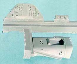
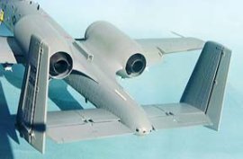
The engine nacelles were dealt with next, make your mind up time now, I wasn’t going to use the engines supplied but I did use the resin exhaust parts, so parts J1, J2 and J3 were made up and the exhausts, suitably painted with Hu polished steel, were inserted, next the intake fans (very nicely detailed, you can see between each blade of the fan) were painted up and built into the nacelle front part as supplied, although they should be a bit deeper placed I decided to leave them as is. This unit and the doors were now added to the main structure and checked that all was lined up correctly after which the whole lump was cemented to the fuselage, there was a slight gap at the front end which I “filled” with a strip of 30thou card which was then sanded to shape when hard. Although I never used the resin engines I have seen them made up in a few models and they look very good indeed, so the choice is yours.
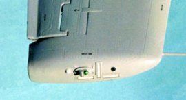
I built up the undercarriage legs, and some brake line plumbing was added before spraying, these were then cemented in with superglue but no wheels or doors were added until later, this makes handling easier when painting. Now all the antennas and air intakes etc can be added, as can the fuselage strakes and the pave penny pod.
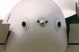
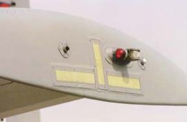
If you want the slime lights onboard then now is the time to mount the “bases”, there is a strip of four sections up the fins, an inverted T set on the wing tips, a single either side of the cockpit and a pair on top the fuselage right behind the canopy in a V shape. Two strips of two are on the rear top fuselage and a pair of singles below. I cut these out of 5thou card with measurements to match whichever decal I am using, appx 1.5mm wider and longer than the decal. Use cement sparingly when adding these or it will eat its way through.
Cutting Edge, supply a new HUD frame work which just has to have the backing resin sanded away to give those delicate side frames, you need to cut two “glass” parts from clear plasticard and fix the between the frames with a drop of PVA glue before mounting I also like to paint the small circle on the base silver so it will reflect a bit of light. Adding the wind shield and all the pylons was the last job before painting, no launch rails or steadies until later.
Windshield and canopy were masked with Tamiya tape and the canopy placed temporarily in position with PVA glue to mask the cockpit, the U/C legs wrapped in kitchen foil, and two discs cut from an old photo were placed in the intakes, with tissues around the exhausts. I used the two-tone greys camo but won’t bore you with details. A couple of coats of Klear were sprayed on before the decals were added.
I wanted a Bentwaters machine and their markings are not available on sheets as yet so it was into the “decal bank” for various codes, the rest came from one of the sets from Cutting Edge Decals 32020 and 32021, I found the stars and bars on these sheets to be too small so I spoke with Dave Klaus who tells me that he has printed replacement sheets with the correct sizes and these will be sent out to all his customers who bought from him, any reprint runs will be corrected. Cam Decals also make some sheets for the A-10 in 1:32nd scale.
Another coat of Klear to protect everything and then a coat of Revell No2 matt varnish was dusted over that to tone it all down to a nice sheen.
When all was unmasked the canopy had the resin details added and the lifting mechanism was partially assembled then hand painted matt black, keeping just below the outer grey colour line. Various other details were added including some etched brass mirrors and set-aside until last of all.
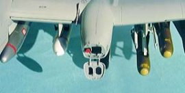
There are numerous stores to load under the wings and the instructions show four typical war loads charts so you get them right, make up the weapons you require and add them and the steadies at the same time to ensure correct alignment.
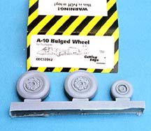
When I was happy with all the construction I added the final details such as the resin bulged wheels and the canopy mechanism. The undercarriage doors were added and the nav lights painted silver before adding a touch of Tamiya clear red or green to each lens.
I think that covers every thing, my opinion? Well the obvious problem is which version is it supposed to be! But once you have sorted that out note that the detail is as good as it gets anywhere, some bits not totally correct but nicely done all the same. Remember this is the only game in town so we should thank Trumpeter for being so bold, or we would still be stuck with some 1:48th scale kits which also aren’t terribly accurate, I feel sure that they will only get better as time progresses.
© Ted Taylor
This article was published on Wednesday, July 20 2011; Last modified on Saturday, May 14 2016