
Hasegawa 1/32 Boeing P-12E
By Michael Rohde
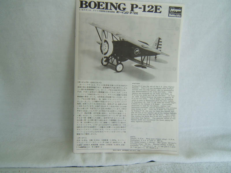
Boeing P-12E History
Towards the end of the 1920s Boeing started to develop a new aircraft to replace the Boeing F2B and F3B of the US Army and Navy.
The first test flight of the new model P 12 took place on the 25th June 1928. The P-12 was smaller, lighter and more agile than the F2B and F3B.
The P-12 was powered by the same type of radial engine – the Pratt & Whitney R 1830 Wasp – and – being smaller and lighter achieved a higher top speed and a altogether better in flight performance.
Further tests were carried out by the US Navy which led to a order of 27 P-12s now called model F4B-1. The US Army Air Corps also conducted tests with the new P-12 and ordered a number of these for the USAAC. Boeing delivered a total of 366 P-12s to the USAAC between 1929 and 1932. Production figures of all variants reached 586 P-12 (F4Bs respectively).
The P-12 served with these USAAC units:
- 17th Pursuit Group - Philippines
- 20th PG Barkdale Field - Louisiana
- Older P-12 variants were also deployed overseas:
- 3rd Pursuit Group - Philippines
- 16th PG - Canal Zone
- 18th PG - Hawaii
Newer variants (P-12 D-E-F) did serve with first line units until these were replaced by Boeing P-26 monoplanes in 1934.
Airworthy P-12s were used for advanced pilot training until 1941.
Non-servicable P-12s ended up as instructional airframes to train aircraft mechanics.
Technical Data:
- Crew: 1
- Length: 6.19m
- Span: 9.14m
- Height: 2.74m
- Gross Weight: 1220kg
- Engine: 1 x 500hp Pratt & Whitney R 1830-17
- Max Speed: 304km/h
- Cruising at: 257km/h
- Range: 917km
- Max. ceiling: 8020m
- Armament: 2 x .30 cal (7.62 mm) Browning 600 rounds per gun or 1 x .30 cal Browning and 1 x .50 cal (12.7 mm) Browning 200 rpg
- Bombs: 111 kg max carried externally on 2 racks mounted on the lower wings
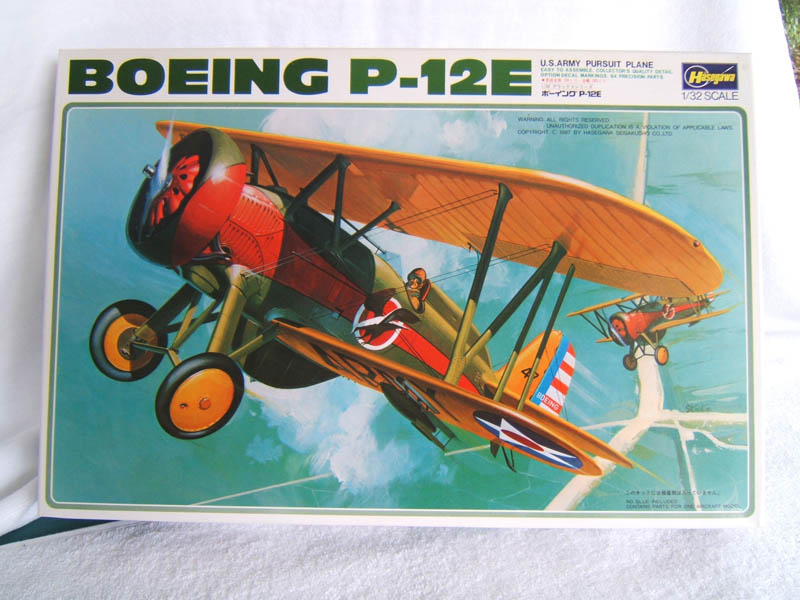
The Kit
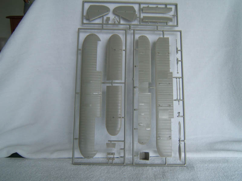
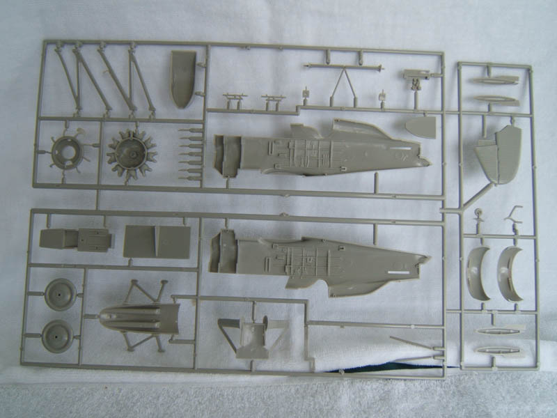
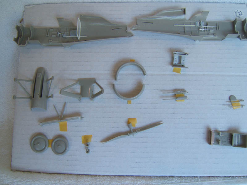
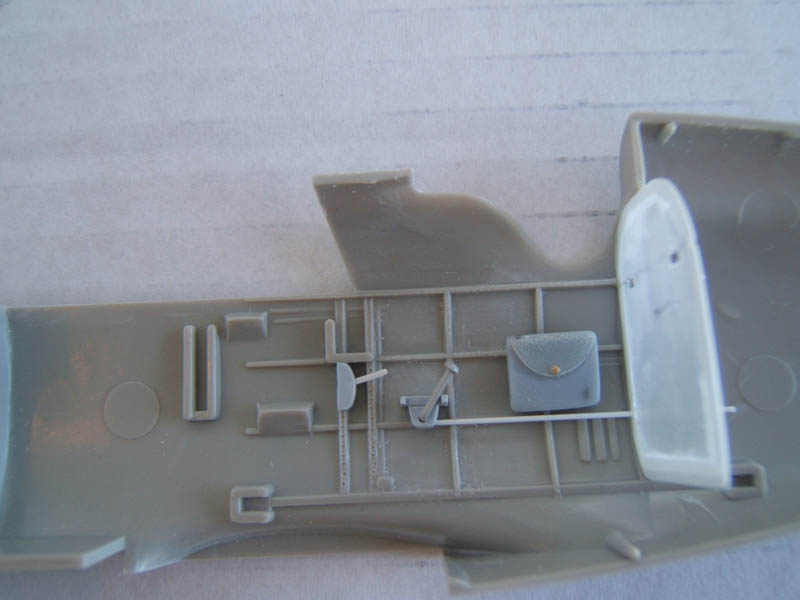
This kit was released as early as 1971 and was re issued again at the beginning of the 1980's and 90's The kit consists of 2 frames with 50 light grey plastic parts and 1 clear part for the wind screen. Considering that this kit was designed and manufactured 46 years ago I must say that the overall standard and quality of this kit was well ahead of its time.
Surface details are raised and finely moulded. Very few flashes and minimal mould shift. Ejector pin marks are shallow and fairly easy to remove.
The cockpit area contains ribs and stringers. Further details are formed as shallow reliefs. There is no rear cockpit wall. The pilot seat is a bit on the chunky side. A ideal case for some scratch building! A simple cockpit floor with basic controls (stick and rudder bar) Instrument panel and a set of 2 guns complete the interior.
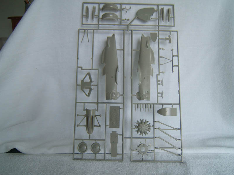
The engine is provided as one piece (engine front cover cylinders, pushrods) But all exhaust stubs and the carburettor intake manifold ring are all separate pieces. Again – some surgery here could improve the overall looks.
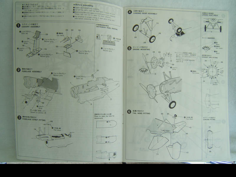
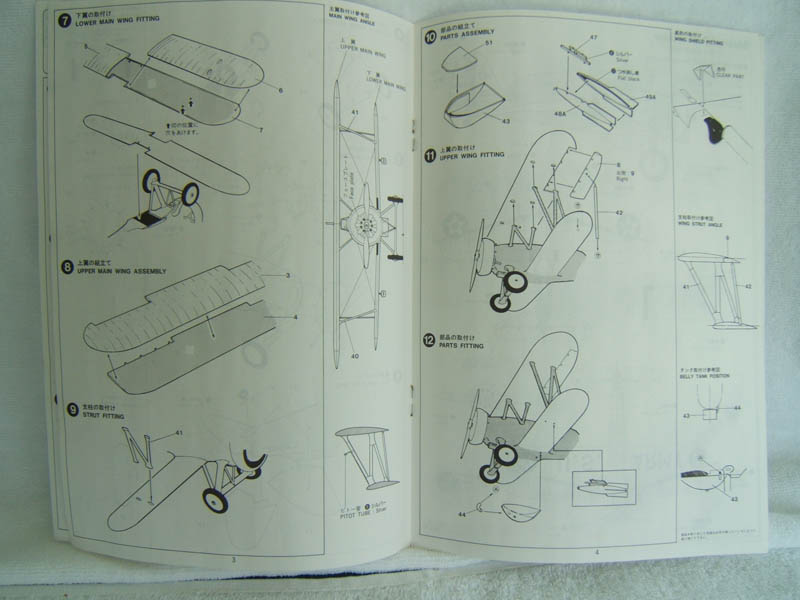
Fin and rudder, tail plane and elevators are also moulded in three pieces. The Ailerons are separate. Upper and lower wings come as half shells. The trailing edge of the wings are designed in such a way that we have the seams positioned more towards the center of the lower and upper wing surface instead on the edge. The kit can be done as fighter bomber and/or a long range version with a belly tank. The instruction sheet is basic and no diagram for the rigging is provided.
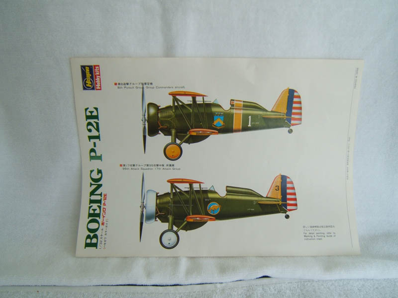
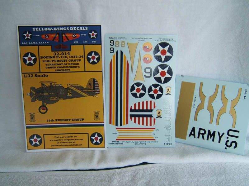
The original decals are past their best by date but Yellow Wings does supply a nice set of decals for this kit.
Stage 1: Getting Started
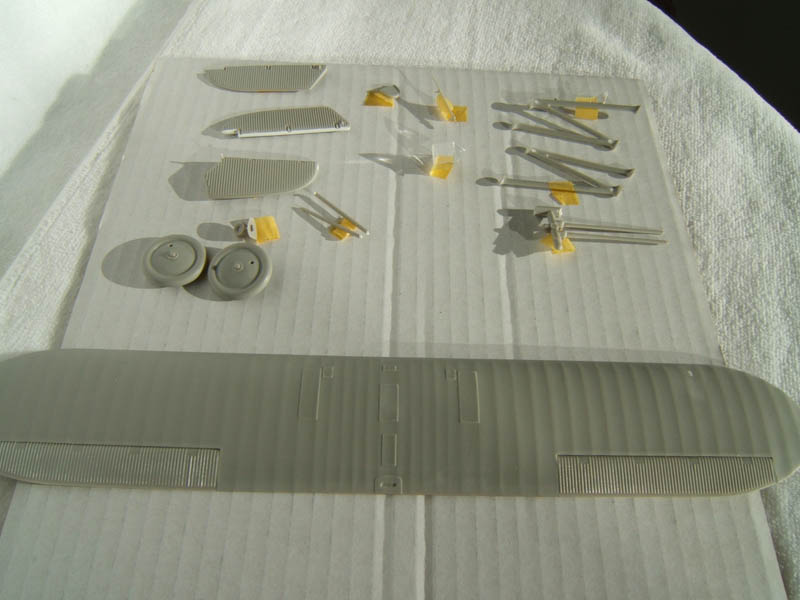
I usually start with removing all the parts from their respective frames and have a closer look under 10 fold magnification.
Flashes, ridges, shrinkages are easily detected and taken care of by applying filler where necessary and careful sanding and polishing using fine grit sandpaper (600 800 1000 grit). I developed a method to dilute Tamiya Putty with Tamiya liquid cement and literally brush on this mix where needed. Advantage: Easier to control in small spaces. Disadvantage: More shrinkage - will require several repetitions to get it right.
A thorough test fit of all parts was done to make sure everything goes together as good as possible and that helps to avoid any holdups down the track. After all, we are dealing with a classic kitset here and one has to expect some difficulties here and there.
Now it was time to do some surgery starting with the fin and tailplane. I carefully separated rudder and elevators with a .10 mm blade model saw.
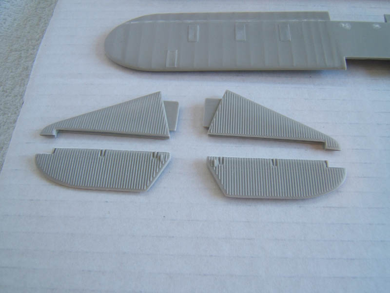
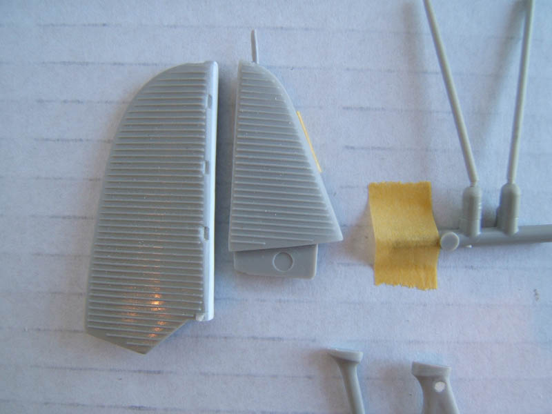
Obviously a straight cutting surface was created by doing this and it was necessary to build up the interface of rudder and elevators to a convex shape and cut recesses on the fin and tailplanes accordingly. Meaning that when rudder and elevators are fitted, these will slot nicely into the recesses provided. And will give us the possibility to mount the elevators in a slight downward position later on.
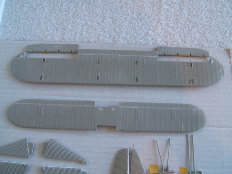
Next the upper and lower wing halves were assembled. Here it was necessary to align the parts, clamp them together to make sure we have optimal alignment and a minimum of seam and step to rectify later on. Tamiya filler along the seams was used sparingly.
The cockpit was taken care of by removing all the shallow details and carefully preserving ribs and stringers. Controls like the throttle quadrant etc were scratch built and the pilot seat was modified as well. First I cut the seat in half. Then the seat base was thinned down to get the right shape and thickness. The back rest and the frame were built with Evergreen .25 mm sheet and .4 mm rod. To come as close as possible to the real thing I looked at photos provided by the Cyber Modellers Website.
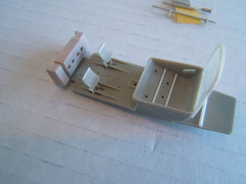
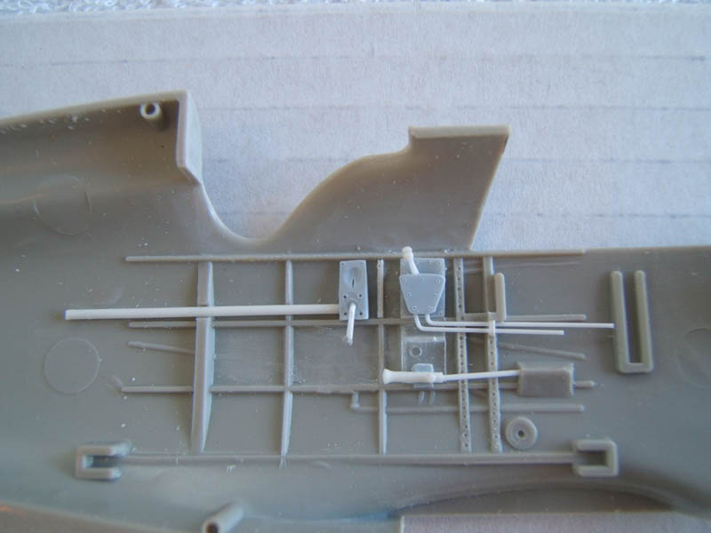
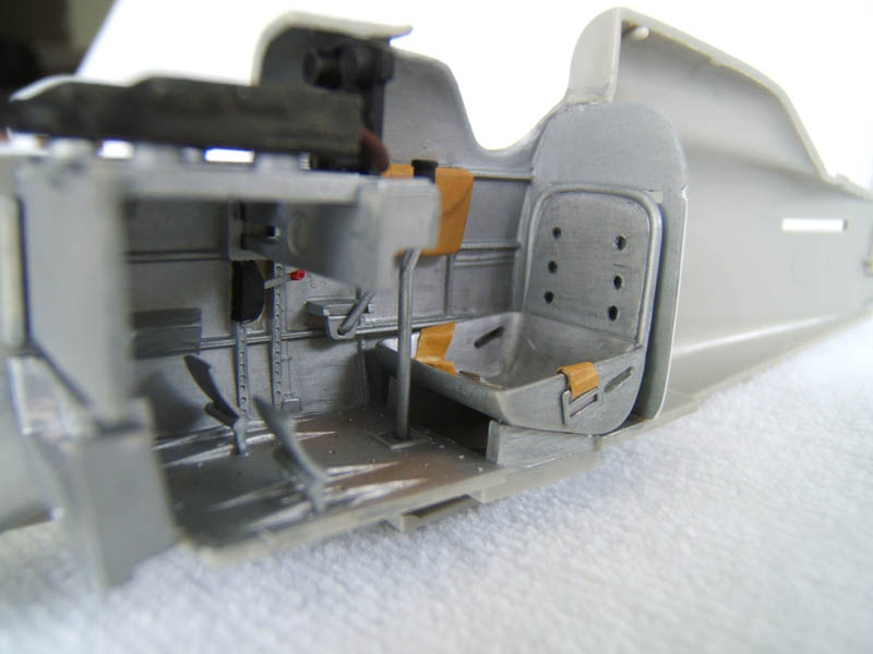
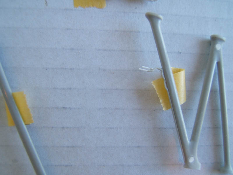
The rear cockpit wall was also made of plastic sheeting stiffened with .4 mm plastic strips. The rudder bar assembly was modified by thinning the foot plates and build the rudder bar linkages with plastic strip.
The machine guns were cleaned up and the muzzles were carefully opened up with a .10 mm rose bur (a dental technicians drill bit).
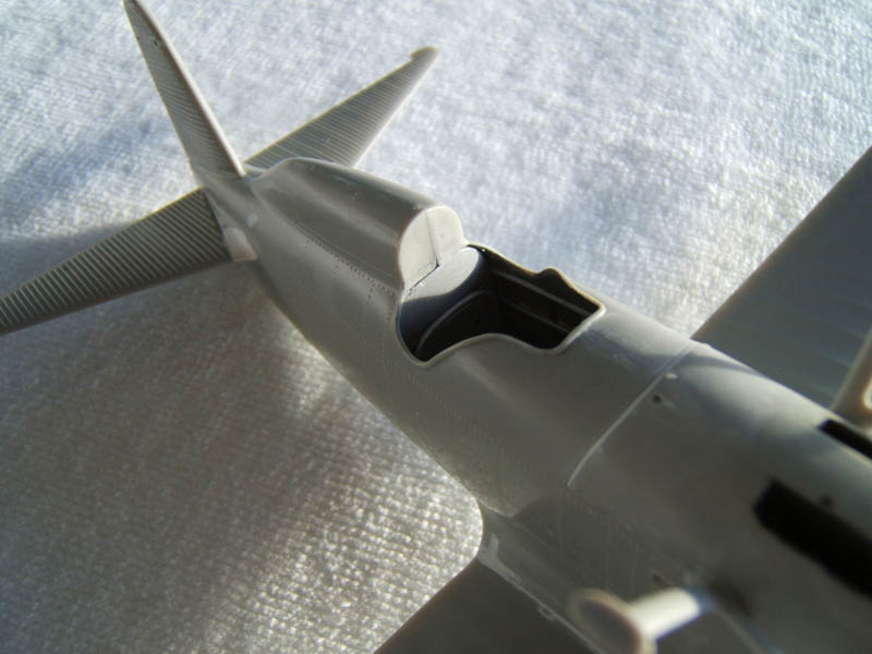
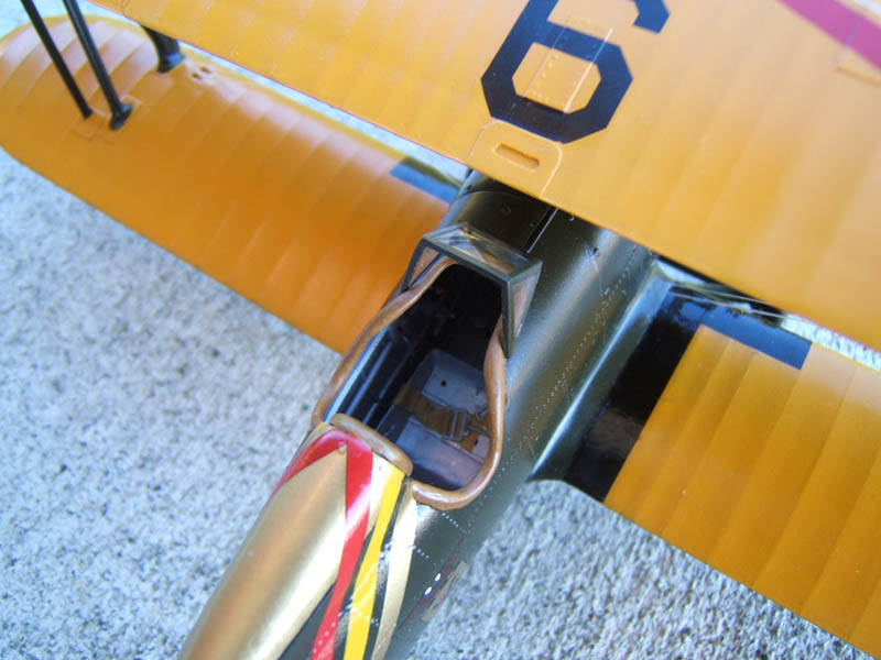
The raised vent on top of the central fuselage panel was hollowed out to give this detail a more realistic look.
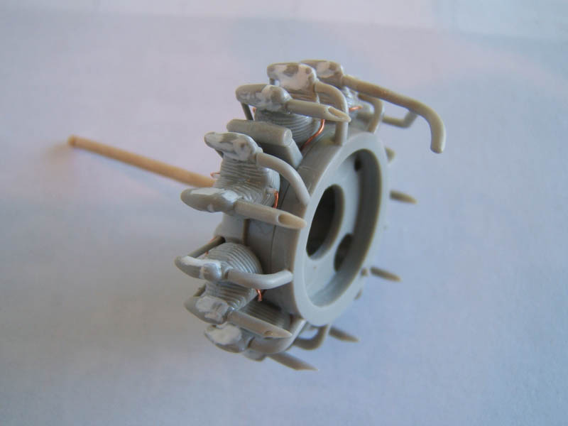
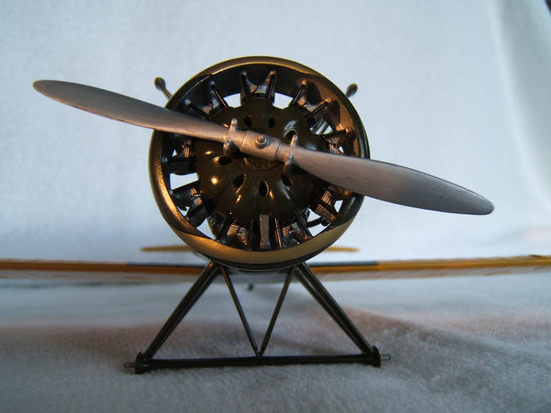
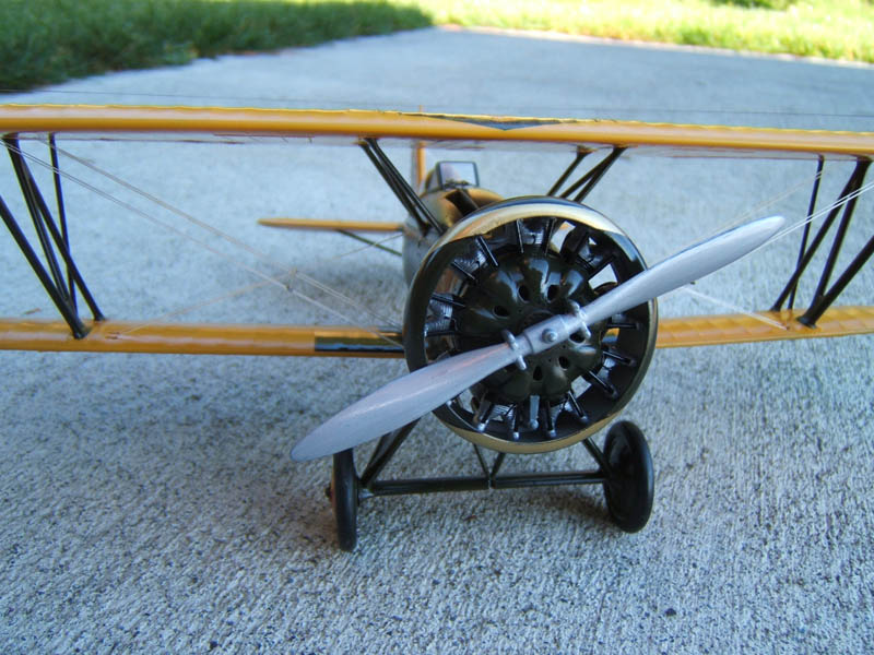
The engine needed a lot of attention. The following modifications were done: Removing all the push rods. Re engraved all the ribbing on the cylinders. There was also a more discernible step (caused by mould shift) which needed to be removed and all cylinder heads needed reshaping with putty as well.
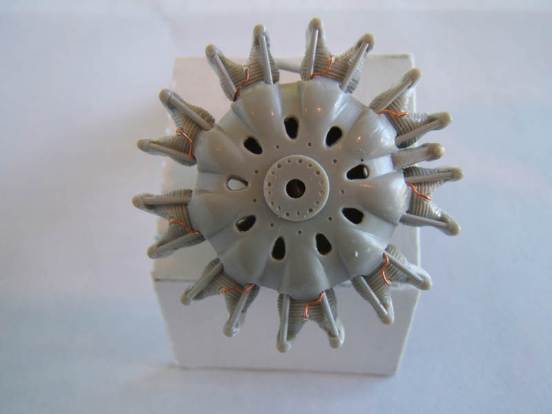
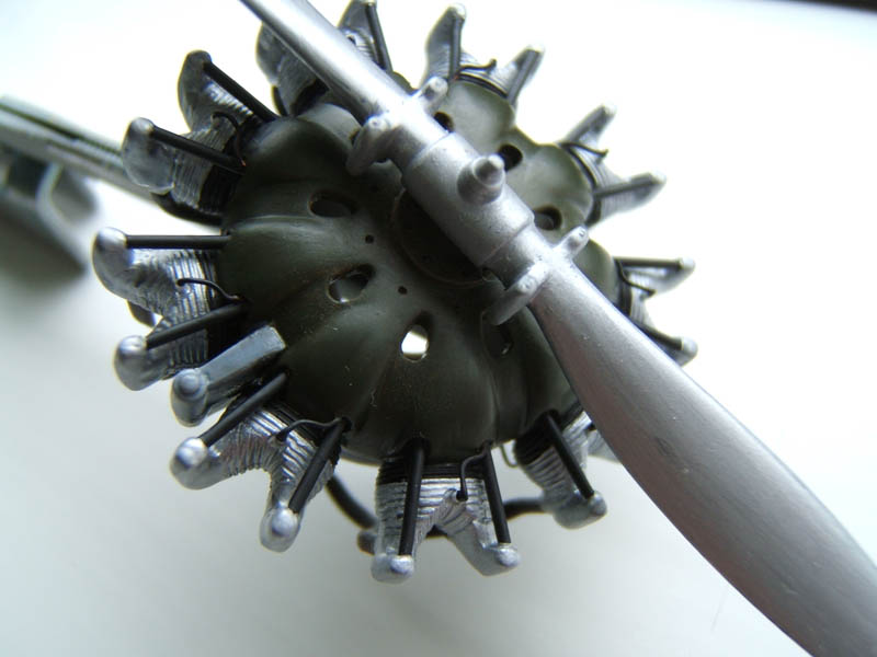
Opened up the air vents in the engine cover. Carefully drilled the recesses for the spark plugs on the front and rear.
Opened up the exhaust stubs to make these look more like the real thing. Carefully adjusted the carburettor intake manifold ring to ensure optimal fit on the cylinder heads (very helpful when bits go together after painting).
All spark plugs were fashioned out of .10 mm plastic rod.
The ignition leads were made with thin copper wire and glued into place with CA glue.
The pushrod tubes were made with the stretched sprue technique, cut to length and carefully glued into place. Photos of a P&W R 1830 were a good source of how to get these details right. The only down side was that the front plate is bigger that the original but I can live with that.
Stage 1A
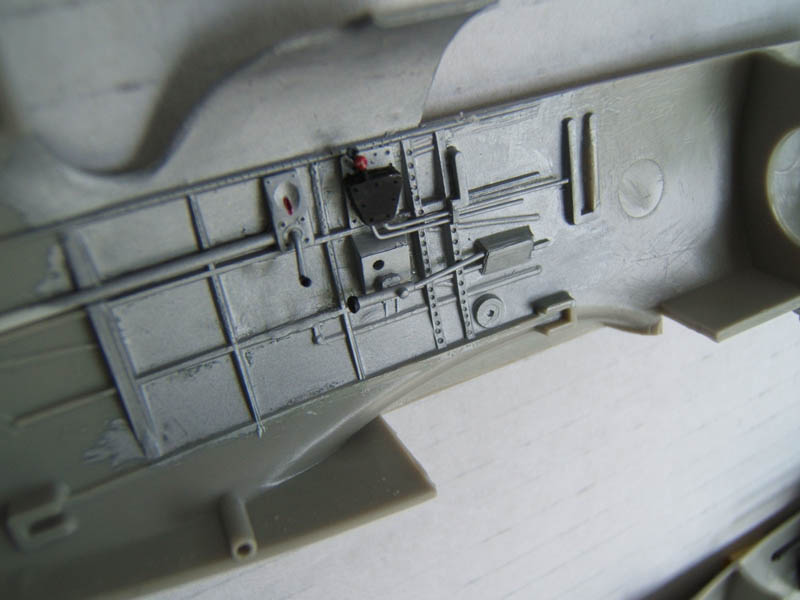
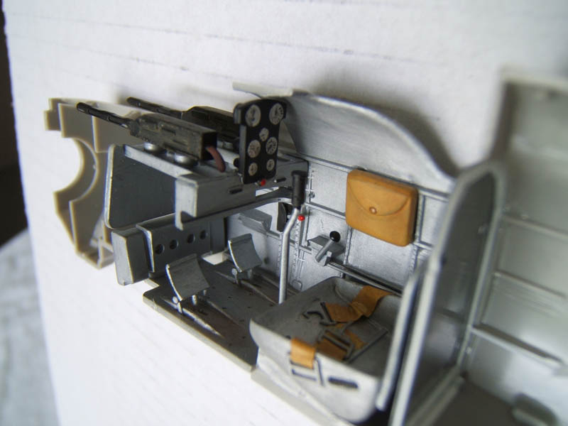
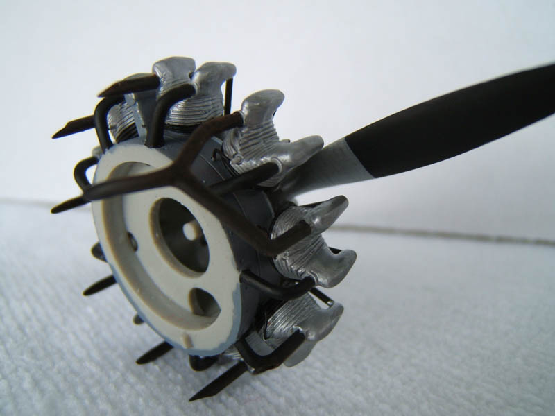
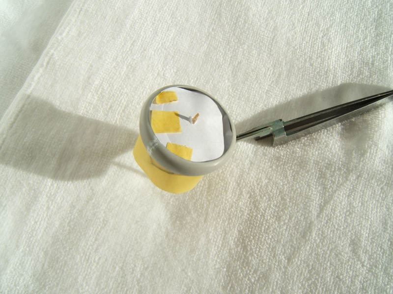
Engine and cockpit details have been painted with a paint brush and then airbrushed with Tamiya X-22 clear. The instrument panel received a coat of flat black and left to dry completely. Next I highlighted the dials with flat white using a small brush with a pointed tip. Let dry thoroughly!
Then I applied small droplets of clear in several stages to mimic the glass lenses on the instruments. The two engine cowling halves were glued into place on the pre-painted engine, seams were carefully filled and sanded down.One had to be very careful not to damage the paintwork or the exhausts. To aid me in this process I used a toothpick as a handle inserted into the opening for the propeller shaft.
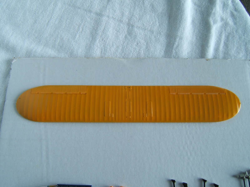
Stage 2
Here we can see that and fuselage plus tailplane and the wings have been assembled. The areas where filling and sanding was necessary are clearly visible. Some of the raised surface details had been affected by this and I did restore lost raised rivets by applying tiny droplets of old CA glue (which is not so fluid anymore) and engraved lost panel lines.
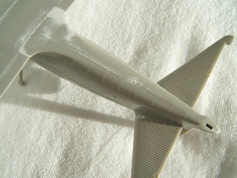
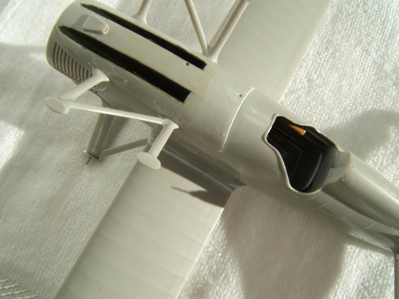
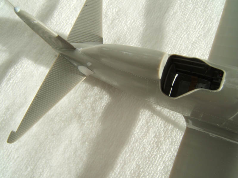
All sub-assemblies are now ready to be airbrushed.
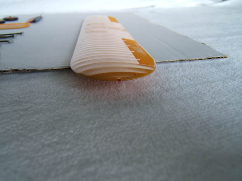
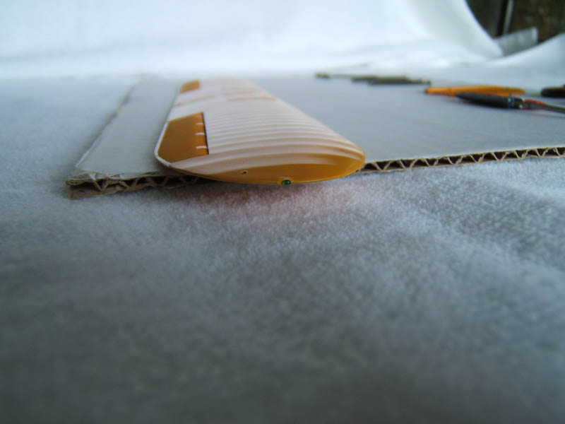
Stage 3
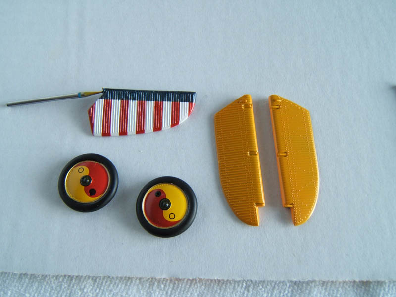
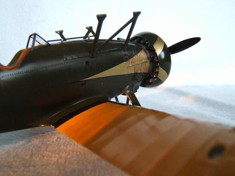
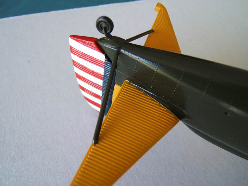
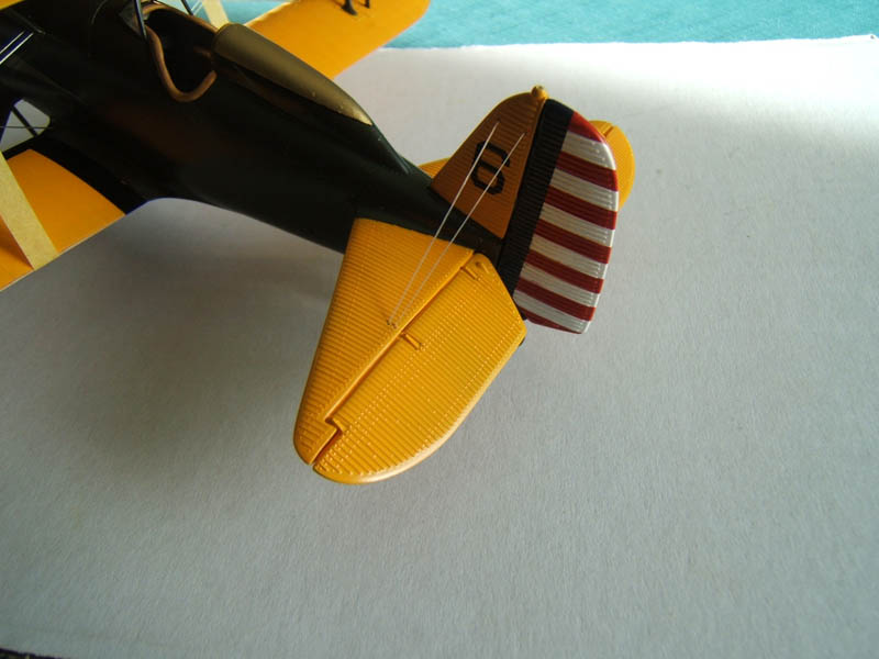
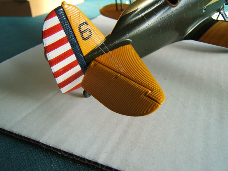
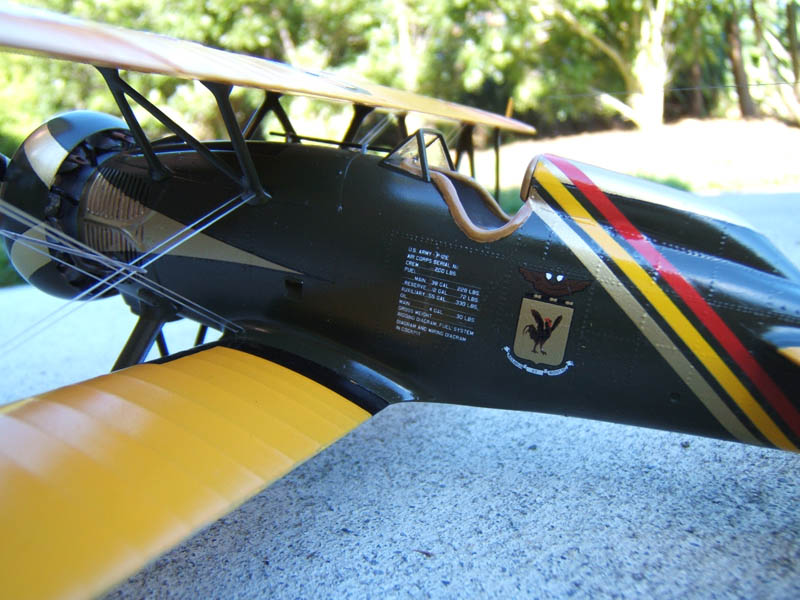
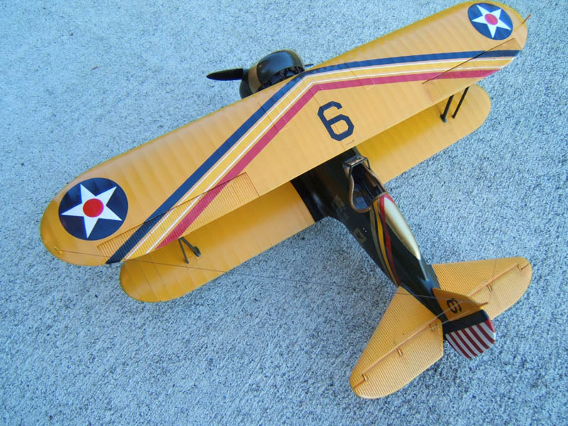
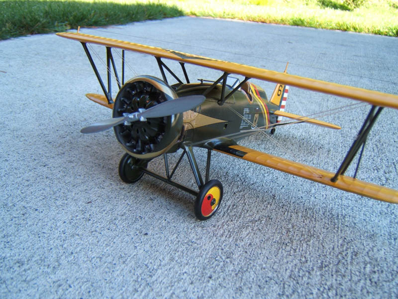
Photos show main components painted and decals are placed on wheel hubs, rudder and forward fuselage. I had difficulties to get the decals for the cowling to settle down because of the shape of the cowling. I decided to mask and airbrush this detail. The same happened with the raised upper fuselage behind the cockpit.
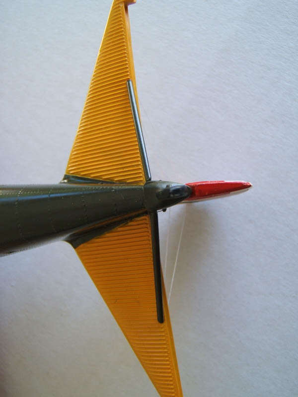
Note the position lights on the wing tips. I made these by drilling recesses into the wing tips. Then I applied tiny droplets of red and green gloss paint into the holes and let dry completely. To make the bulb shaped lights I added drop for drop (each one had to dry first) until I had a decent build up of clear paint resembling a, well, realistic looking position light.
For the overall paint scheme I used:
- Tamiya XF-62 Olive Drab
- X-12 Gold Leaf
- X-22 Clear XF-3 Yellow
- X-7 Red
- XF-1 Flat Black
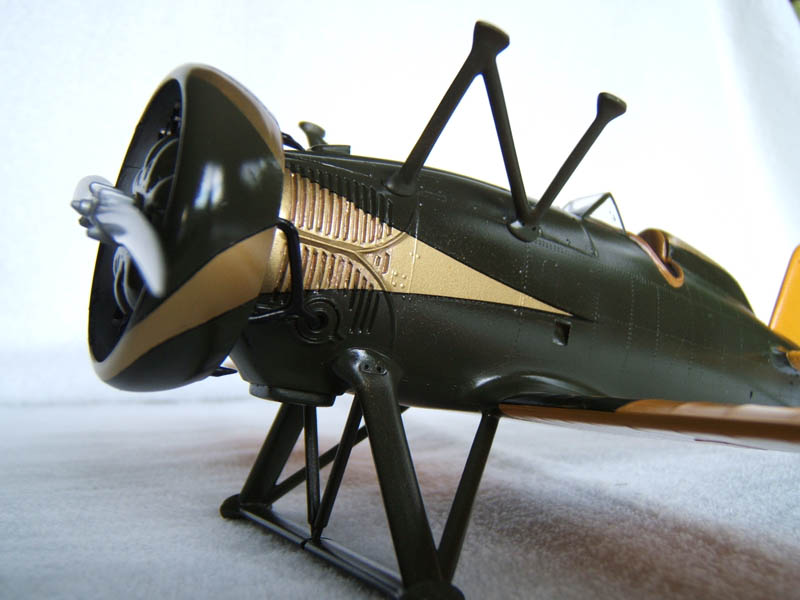
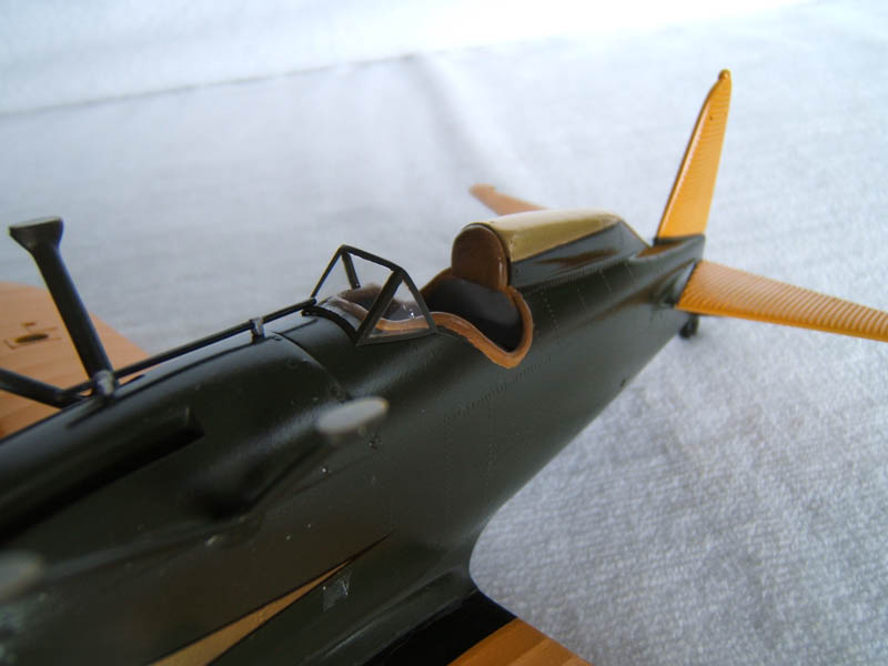
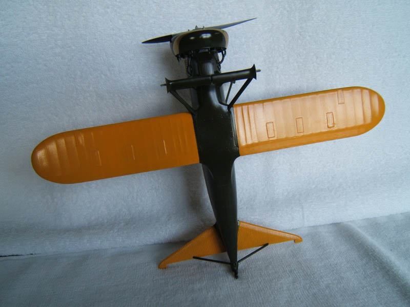
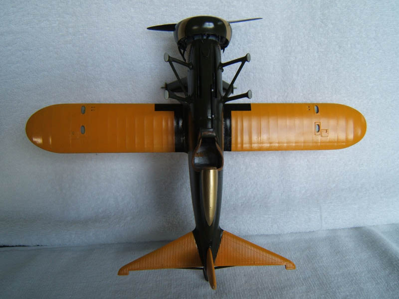
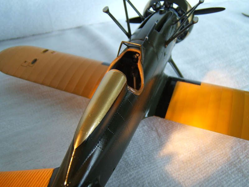
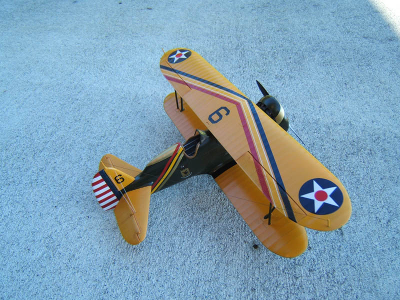
To get the orange yellow hue of the wings right I mixed XF-3 with a tiny amount of X-7. The head rest and cockpit apron was painted with Humbrol 62 (leather matt). I built up several layers of thick paint to get this cushion effect. Again layer by layer had to dry first before the next one went on. Brown Pastel colour was dry brushed on to achieve the appearance of weathered leather.
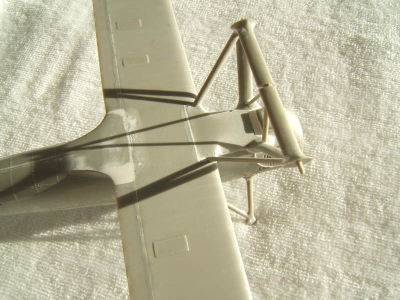
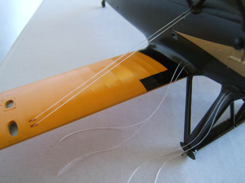
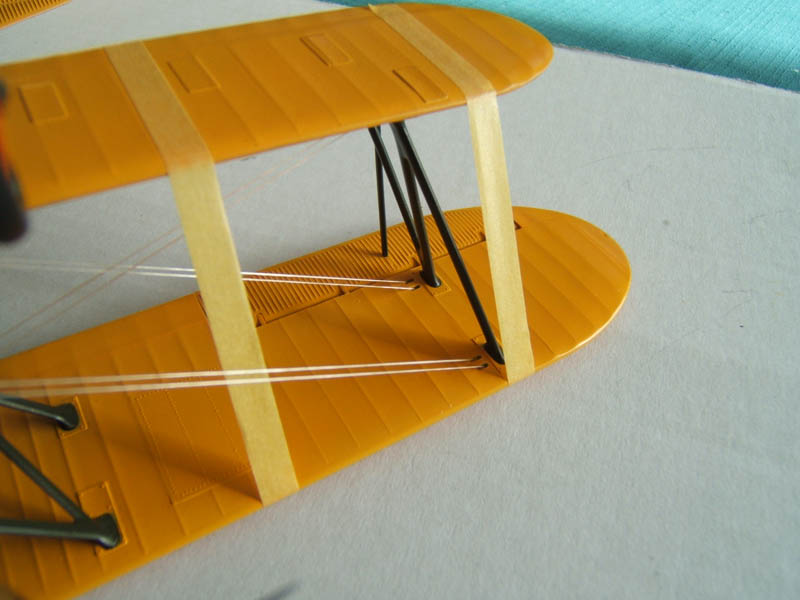
Stage 4
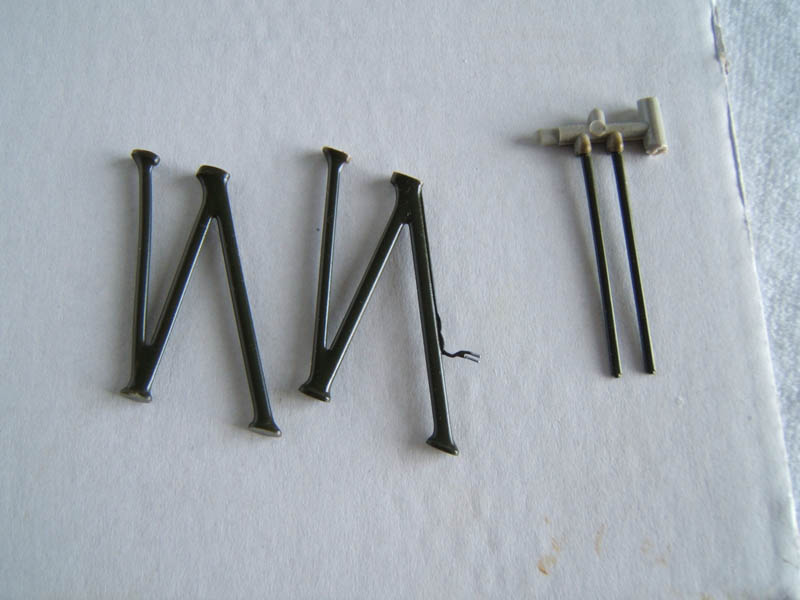
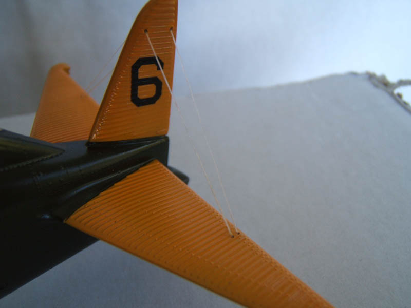
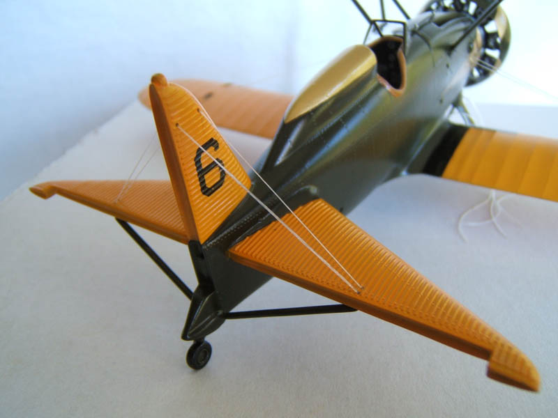
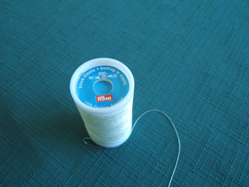
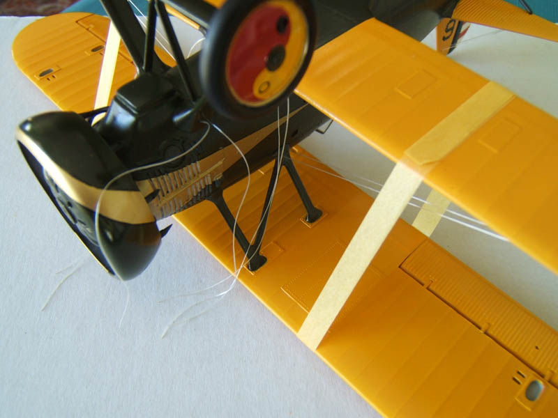
As we can see on these photos I have started with what I would call pre-rigging. The reason to do the rigging in two stages is to have better access to first attach one end of the rigging wires. The material I used for the rigging is a elastic flat profile thread used widely in the textile industry. The flat profile does resemble to some degree the aerofoil shape of rigging wire use on biplanes.
To determine the correct length of the individual wires I used a compass and took into account a certain amount of stretch needed to avoid sagging. The ends were glued into place with a tiny amount of CA glue applied with a self made plastic probe.
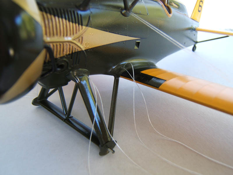
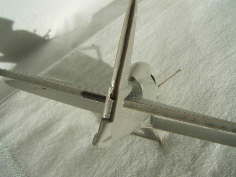
Stage 4B
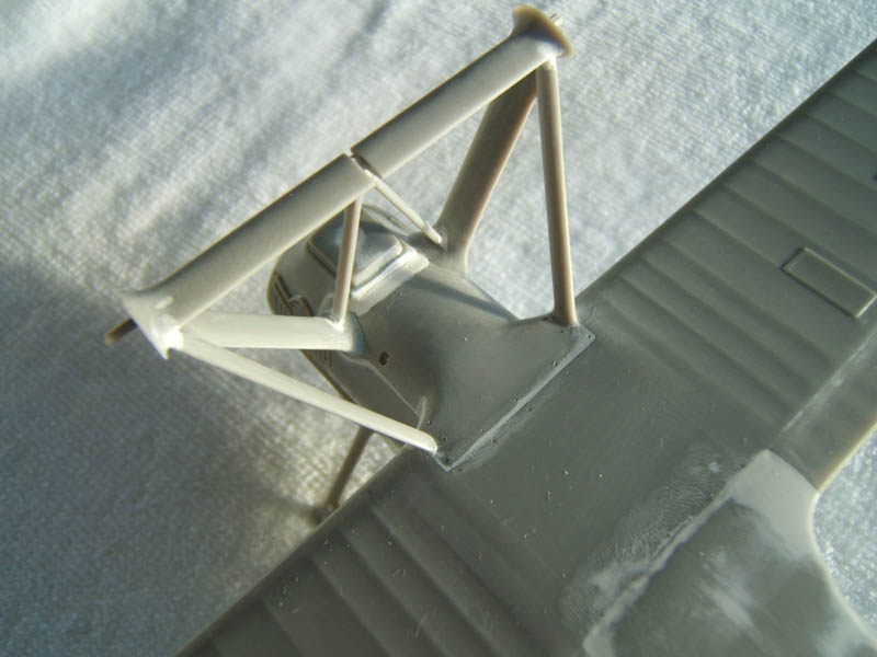
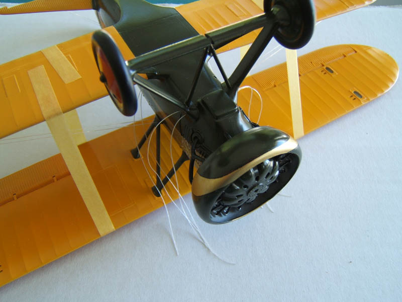
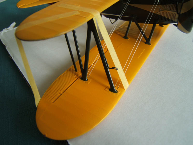
Here we come to fitting the upper wing and support struts. It was very helpful that the kit was designed in such a way that the center/fuselage wing struts were already attached to the upper fuselage panel. That made the alignment of the upper wing so much easier. To make sure that nothing could shift I used some masking tape to secure the wing. CA glue was used to bond everything together.
For the rudder control wires I used elastic EZ-Line (Wingnut Wings).
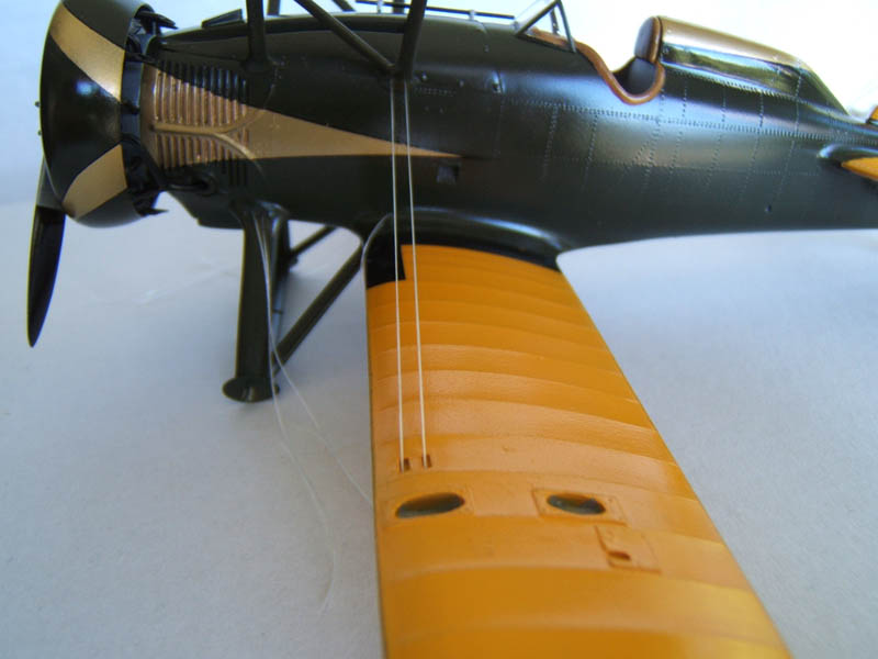
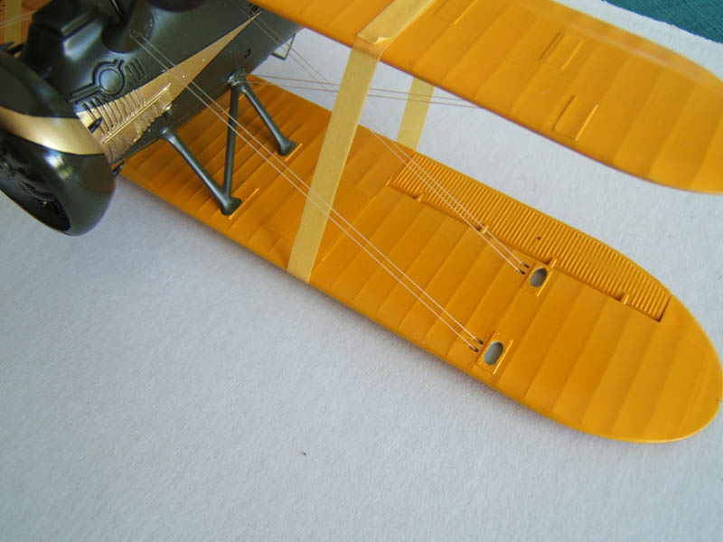
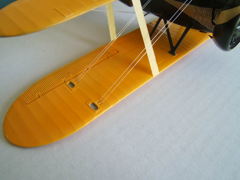
The second stage of the rigging process was the diagonal connection between upper and lower wing. Note that at this stage I have not yet fitted the outer struts so I could get at the attachment points unhindered.
After finishing the main rigging the struts were inserted into their respective recesses on the upper and lower wing. Masking tape was used to stabilize the assembly and to make sure the struts were seated right down. CA glue was applied to bond everything together.
The next step was to carefully glue rudder and elevators into place.
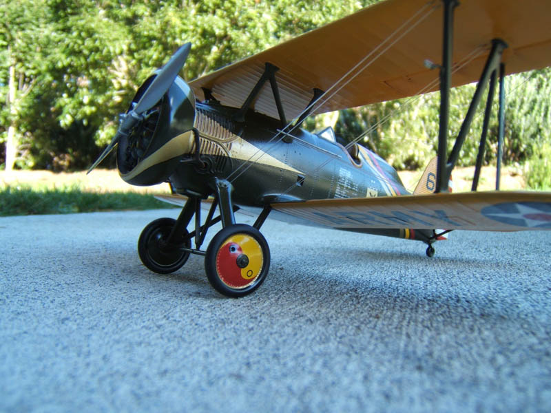
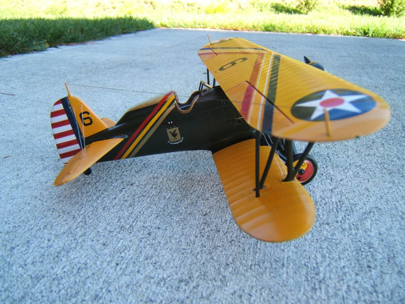
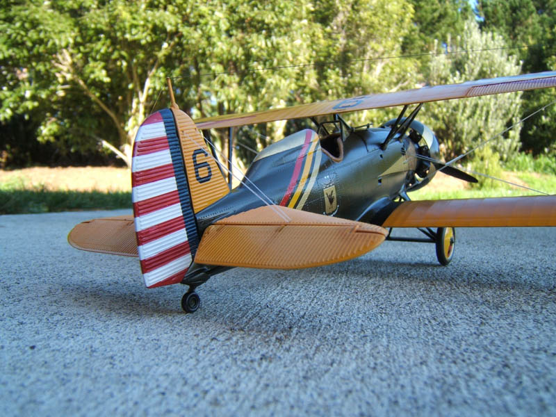
The markings of this particular aircraft are these of the Group Commander of the 18th Pursuit Group Hawaii 1932-34.
After the decals had completely dried these were airbrushed with a thin coat of X-22 clear.
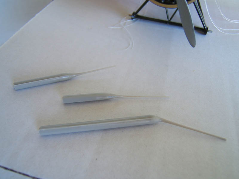
Last but not least the antenna masts were installed and antenna wires were made with EZY Line. I carefully glued the braces where the rigging crosses into place. The were made of plastic rod with sanded down pointy tips and painted with Tamiya XF-16 flat aluminium.
I applied mild weathering only using Pastel colours. Rust colour for the exhausts a bit of medium brown around the seats of rudder elevators and ailerons and a darker brown for the cooling vents and the central engine cover.
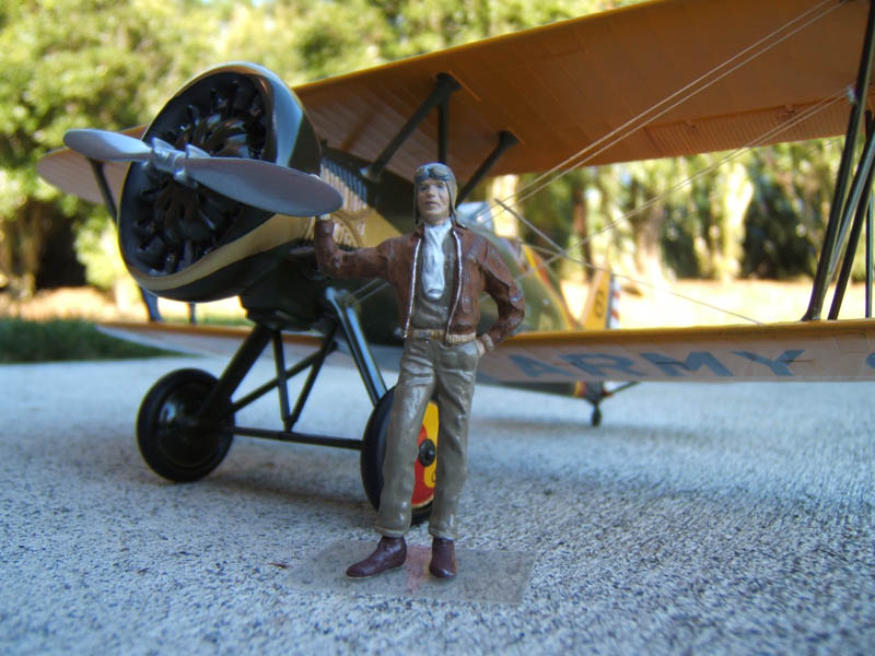
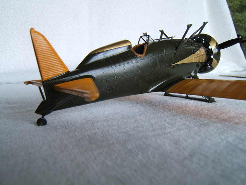
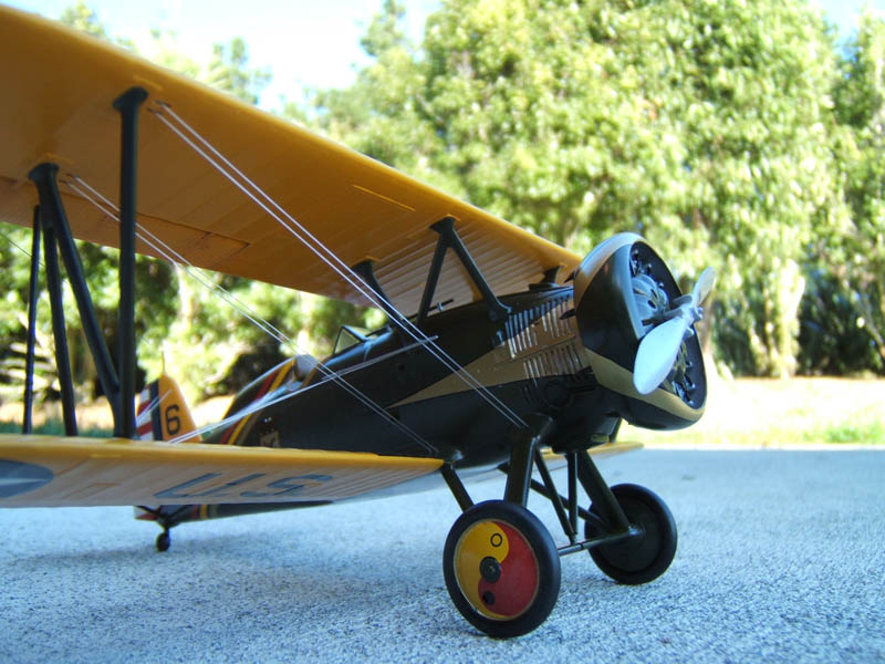
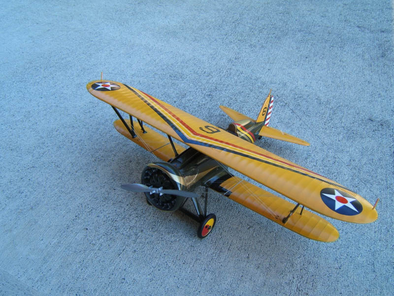
Finished Model
© Michael Rohde 2017
This article was published on Wednesday, June 21 2017; Last modified on Wednesday, June 21 2017