
ID Models/Tigger Models 1/32 XP-82A Twin Mustang
By Suresh Nathan
A Brief History of the Allison-Powered XP-82A
As the Second World War drew to a close, the United States Army Air Forces sought a long-range escort fighter capable of accompanying bombers deep into enemy territory. The North American P-82 Twin Mustang was conceived by joining two P-51 fuselages with a common wing and tailplane, creating a formidable twin-engine aircraft. Powered by Allison V-1710 engines, the P-82 was intended to provide endurance and firepower while reducing pilot fatigue on extended missions. Although the war ended before the type could see combat, the Twin Mustang represented the pinnacle of piston-engine fighter development, bridging the gap between wartime innovation and the jet age. There were 4 XP82A’s. The first two RR Merlin Powered flew well but as the war came to a close America would need to consider royalties to England for further use. Therefore 2 Allison powered variants were fitted. One, 483888, flew (probably) and the other did not. Since this was to become the dominant type of North American F-82 Twin Mustang this is the prototype I chose to build.
The Tigger Models 1/32 Vacuform Kit
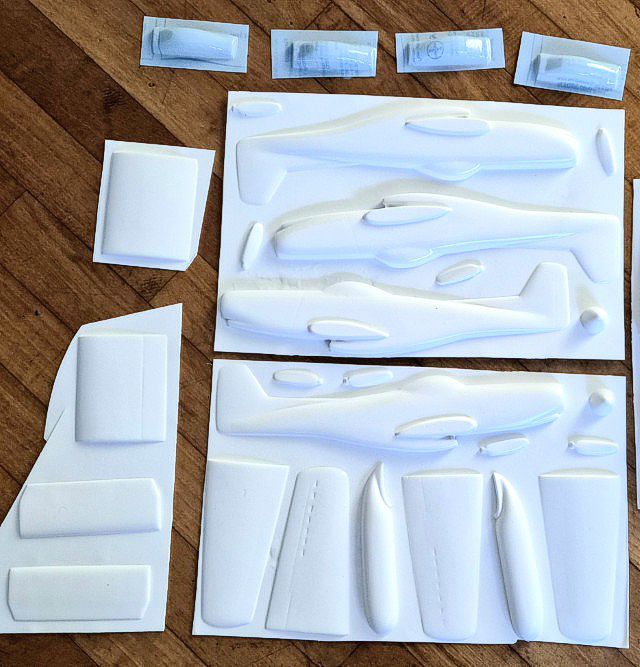
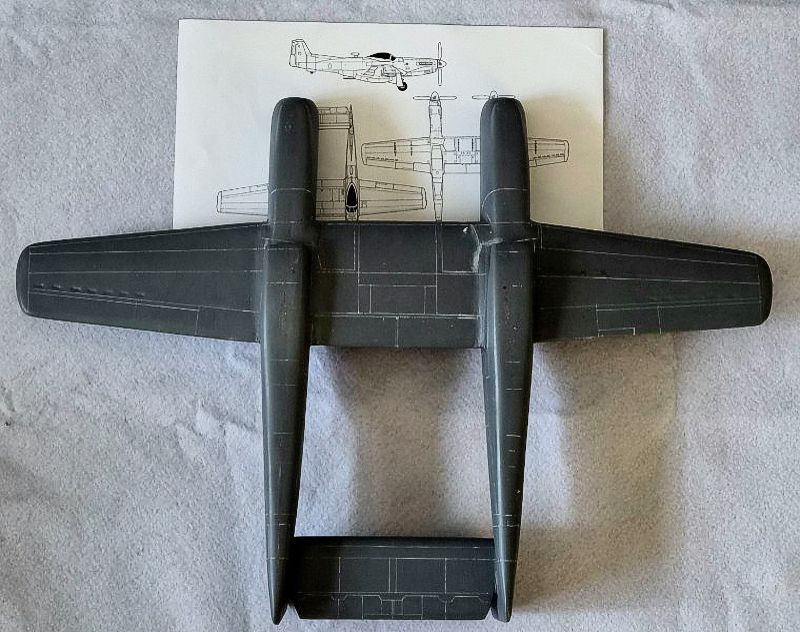
Tigger Models offers the XP-82A in vacuformed format, a rarity in large-scale modeling. The kit arrives as a set of white styrene sheets with the major components—fuselages, wings, tailplane, and nacelles—stretch molded with negligible surface markings. Detail is minimal, leaving the builder to scratch-build cockpits, wheel wells, and surface features. The fuselage halves are cleanly formed but require careful cutting and sanding to achieve symmetry. The wings are broad and thin, demanding internal spars for rigidity. Clear parts are provided for the canopies, though these will benefit from polishing and framing. In short, this is a kit for the experienced modeler: it offers a blank canvas to recreate the unique lines of the Twin Mustang, rewarding patience and ingenuity with a striking finished aircraft. In my version there was significant distortion of the left fuselage. More on this later.
Main Construction
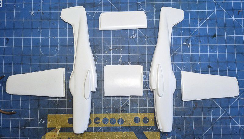
The vacform parts were first cut from the backing sheets using a scriber and straightedge. The fuselage halves required sanding to achieve symmetry and a clean mating surface. Bulkheads were added to provide rigidity and alignment, especially important given the twin-fuselage layout. The wing sections were reinforced with internal spars made from laminated styrene to prevent flexing.
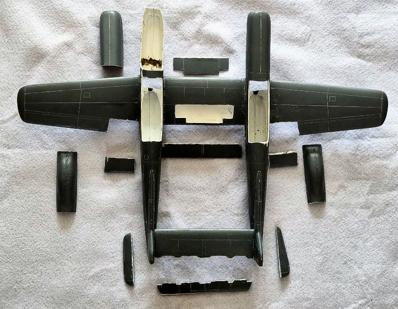
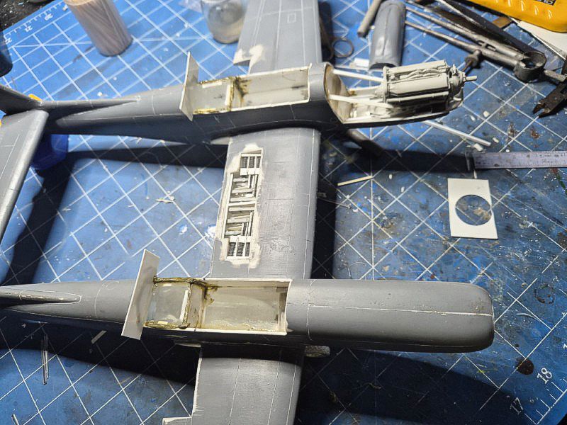
Cockpit tubs were scratch-built using sheet styrene and installed early to allow for fuselage closure. The wheel wells were boxed in and detailed with basic ribbing and plumbing. The nacelles were shaped and faired into the wing roots; this area needed filler and sanding to achieve a smooth transition.
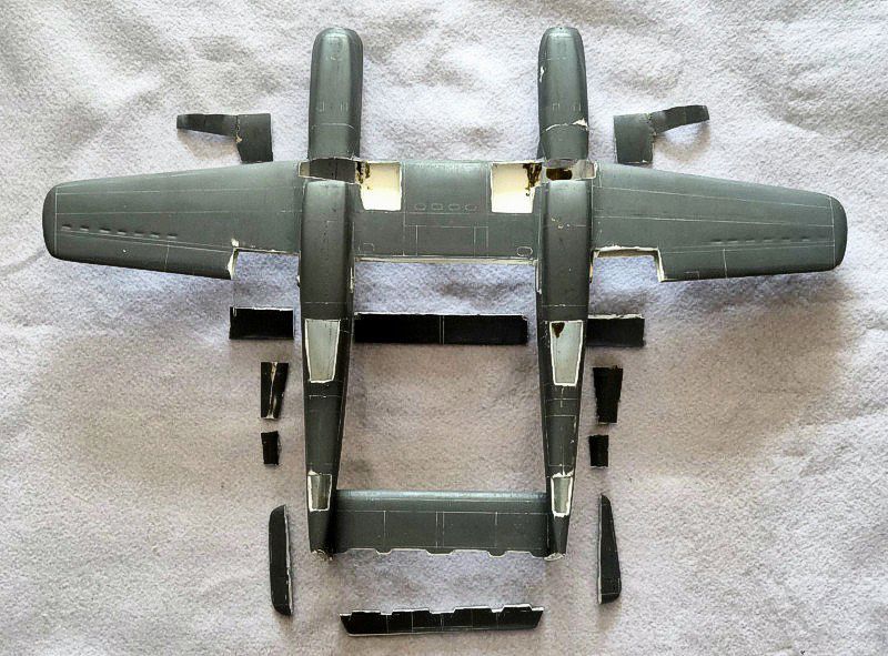
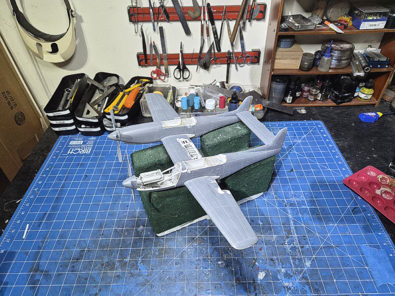
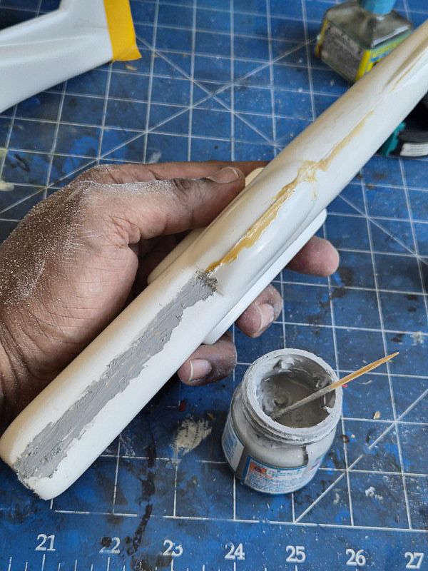
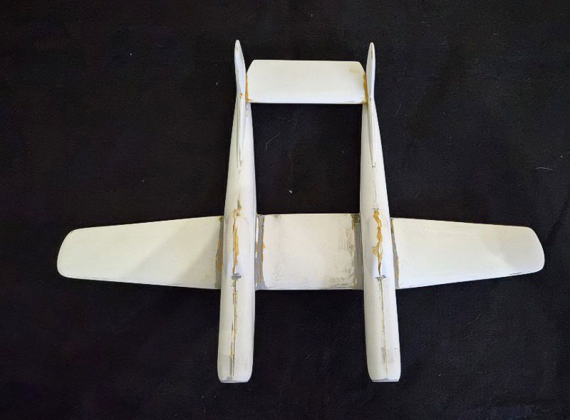
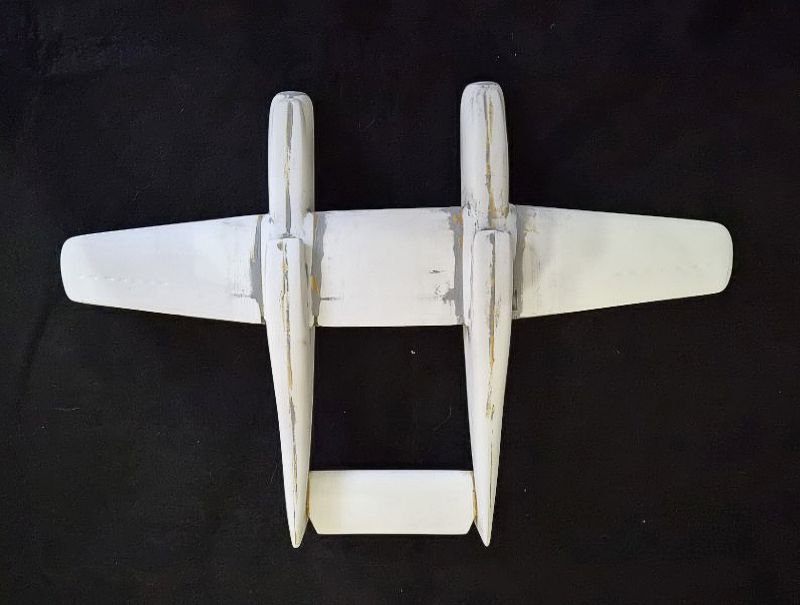
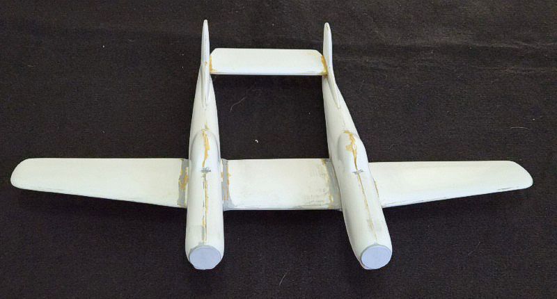
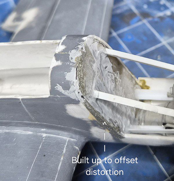
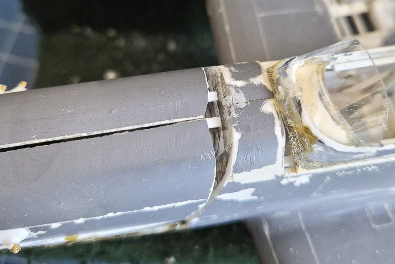
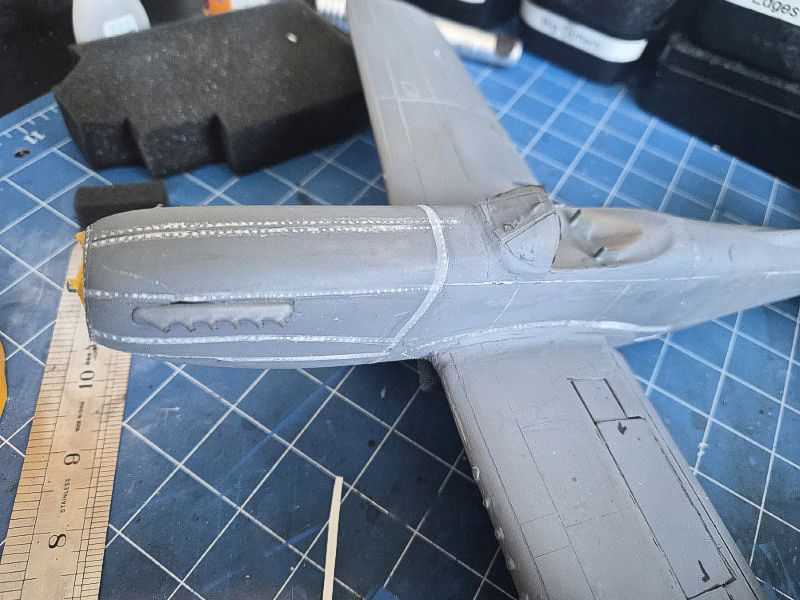
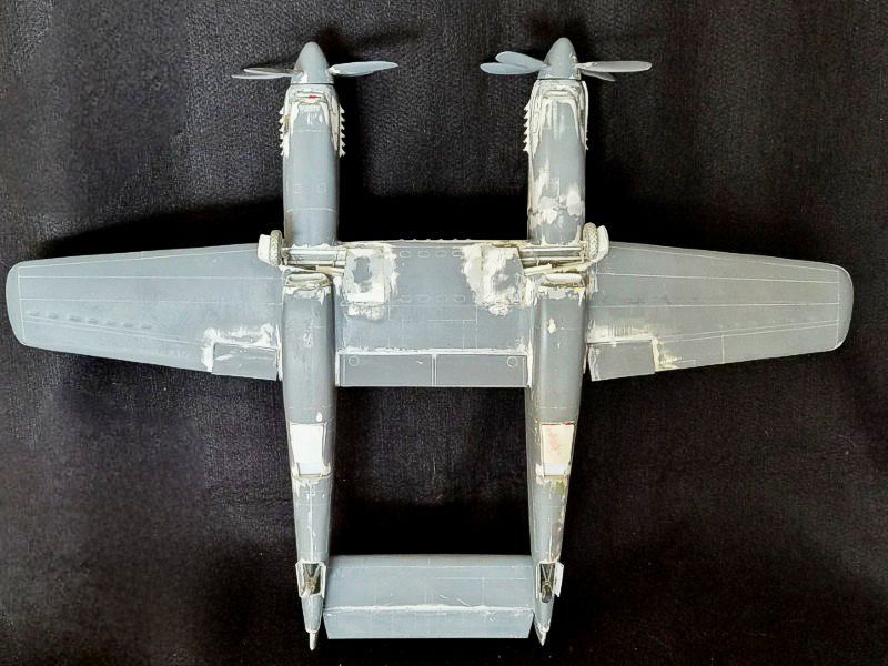
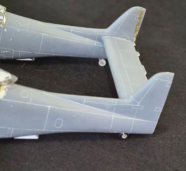
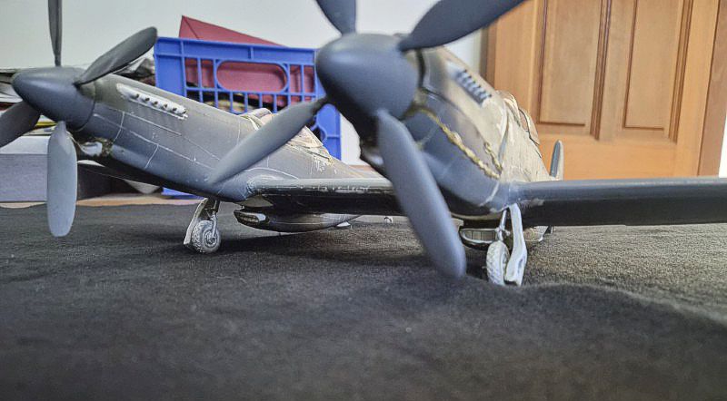
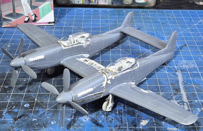
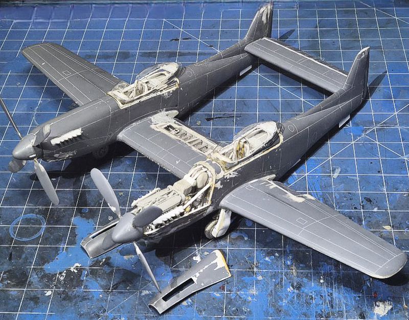
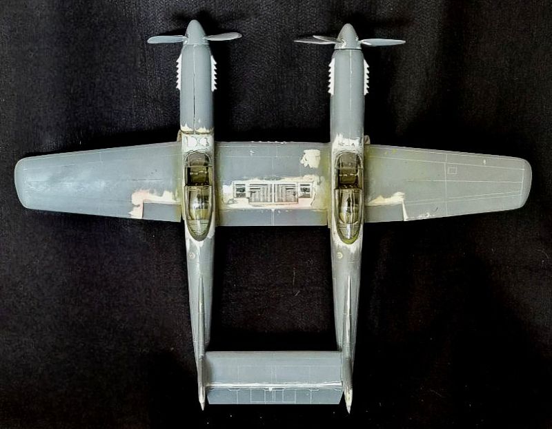
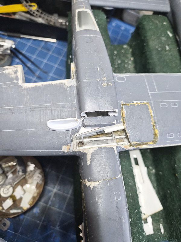
The horizontal stabilizer was slotted between the tail booms and aligned using a jig. Rudders were cut separately and attached after the stabilizer was fixed. The model was then assembled into its full airframe configuration and checked for symmetry across the fuselages, wings, and tailplane. The left fuselage turned inwards and had to be separated at the engine bay and turned outward. This caused a lot of gaps that required much correction and filler. For these kinds of projects, I use liquid plastic or sprue diluted in solvent. Where necessary it is reinforced with brass rod.
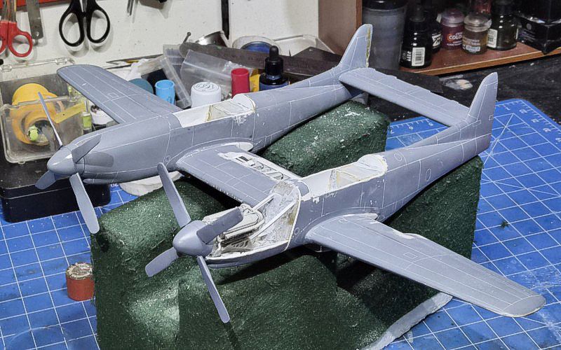
The final steps in this phase included priming the model (Rustoleum) and preparing it for surface detailing. At this stage, the build was a structurally complete shell and ready for detailing.
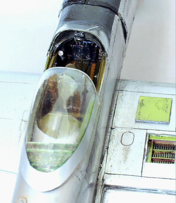
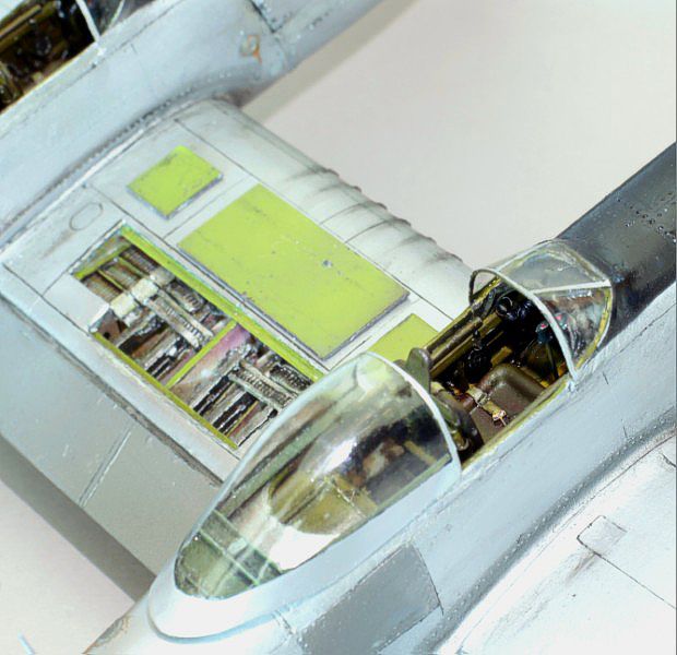
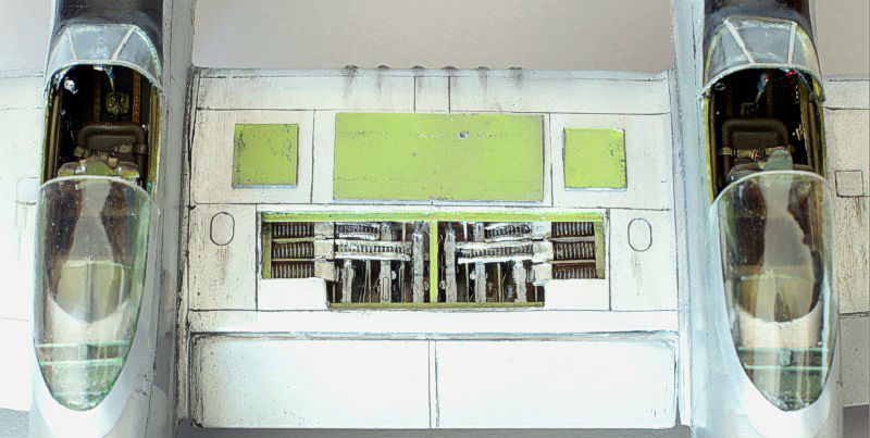
Cockpit
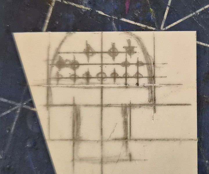
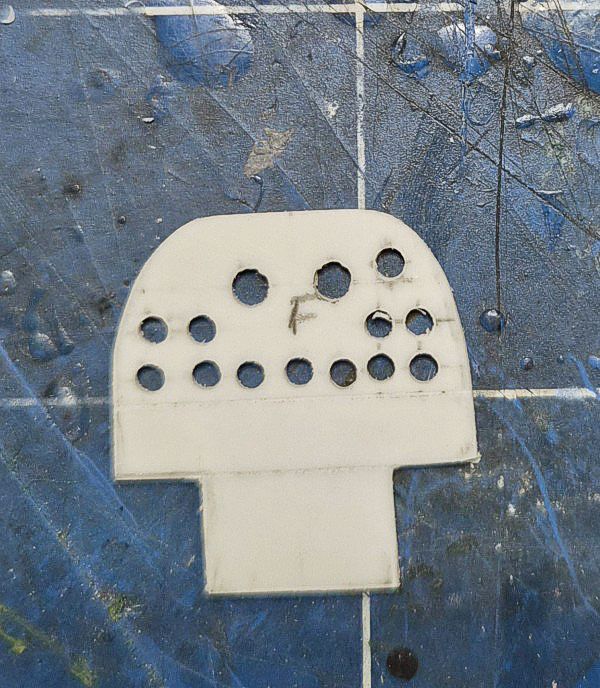
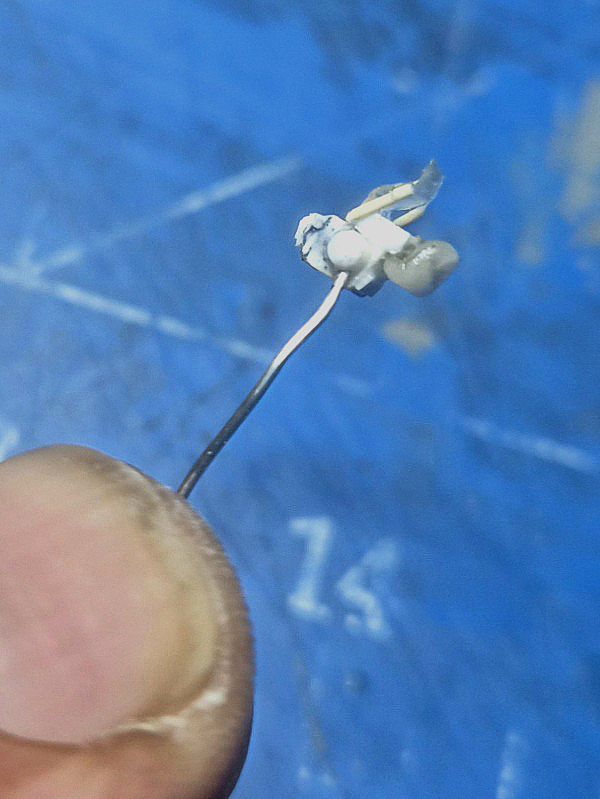
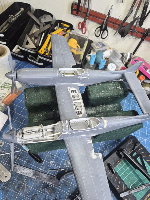
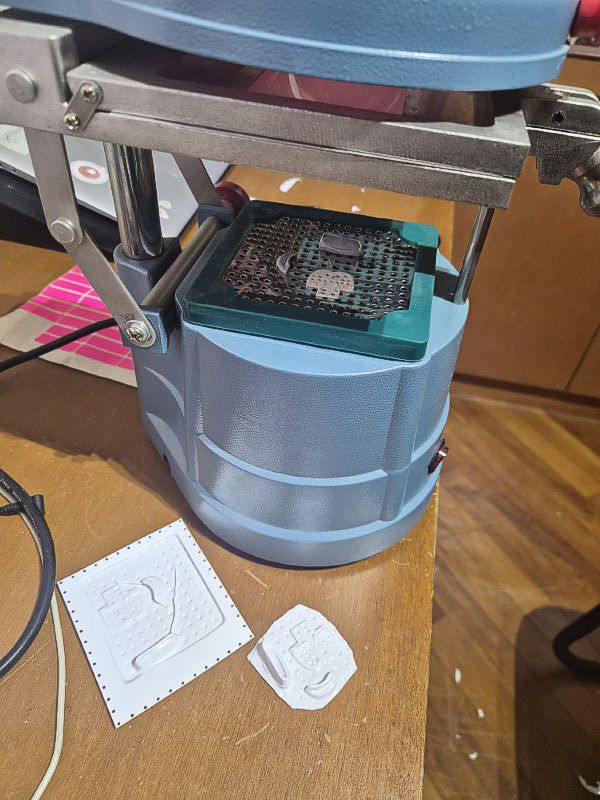
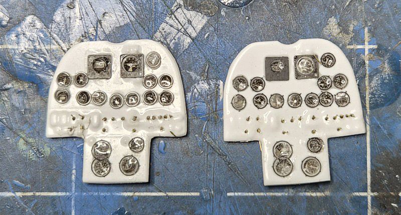
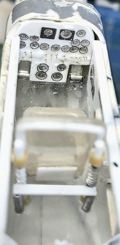
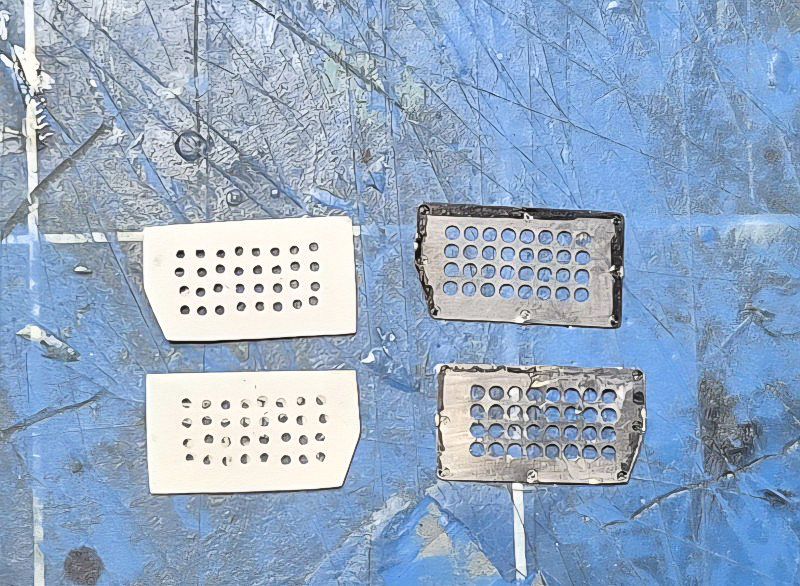
The cockpit was built from scratch using sheet styrene, lead foil, lead wire and Waldron parts. Each fuselage received its own cockpit tub, with sidewalls detailed to match reference photos of late-war Allison-powered Mustangs. The left wall is identical, but the right wall has certain variance. The gunsight is on the left, and the right carries a gun camera. The plane can be flown by pilots of either cockpit so it was otherwise identical unlike the later versions where the right was a radar operator’s station and did not have the same equipment. Instrument panels were constructed from layered styrene and punched bezels, with Waldron dials sealed under UV resin. I vacuum formed the main panels to keep them as identical as possible. Control columns were shaped from rod and wire, and rudder pedals added from bent lead strip.
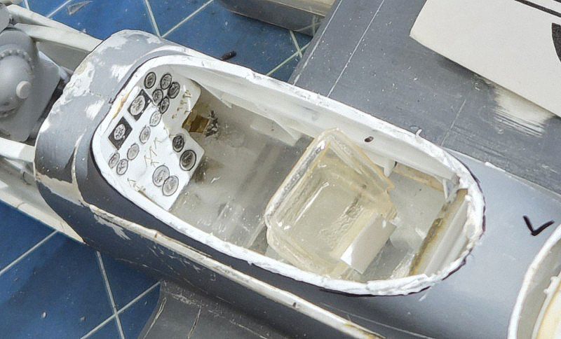
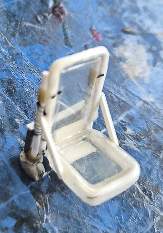
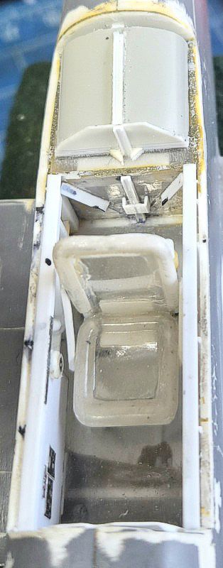
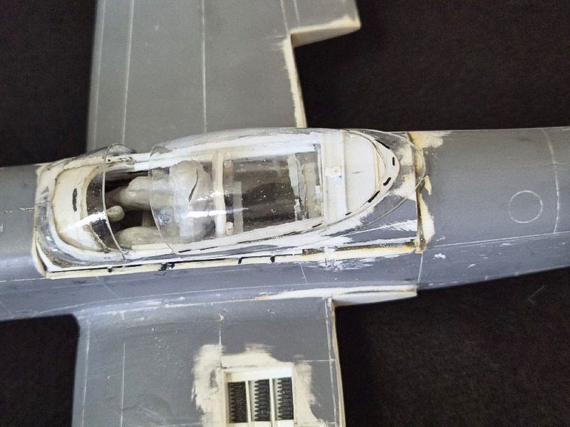
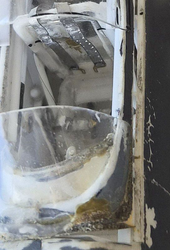
Seats were built from styrene sheet vacuum formed over brass masters with harnesses made from foil and wire. The rear bulkheads were fitted with basic wiring. Canopy rails were added to the fuselage lips to support the vacformed clear parts later in the build.
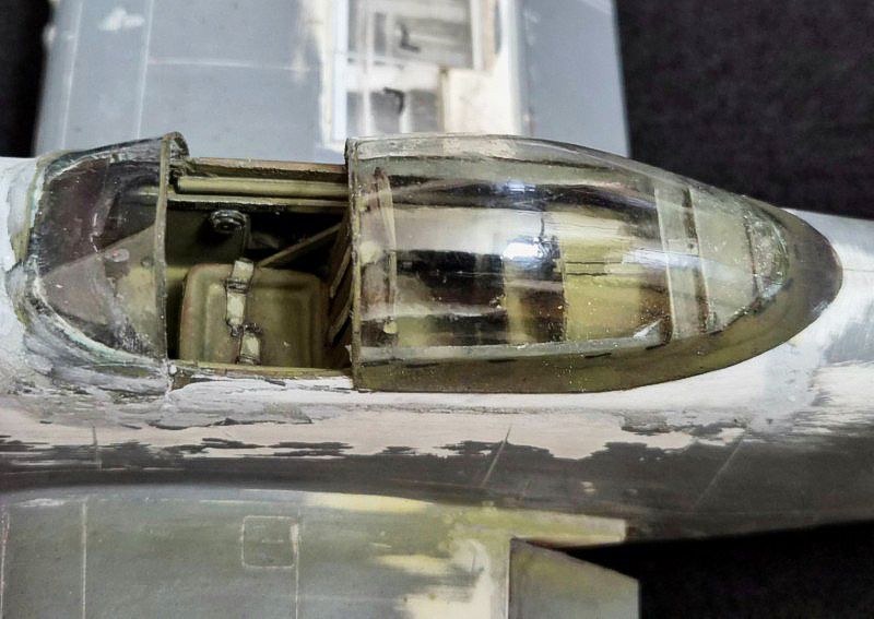
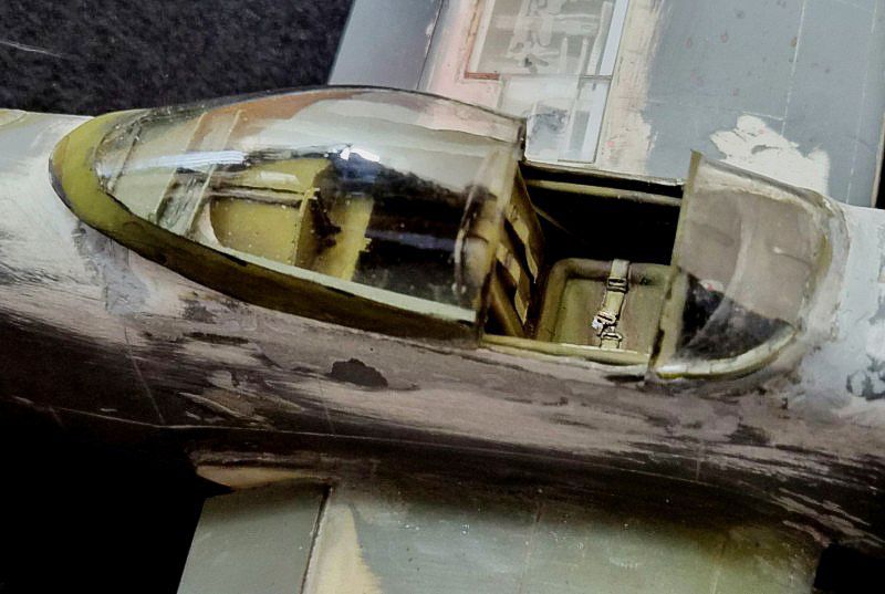
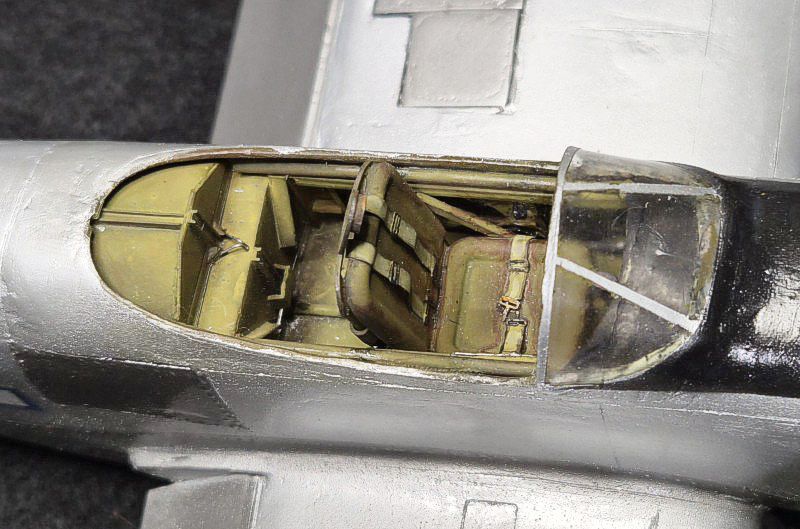
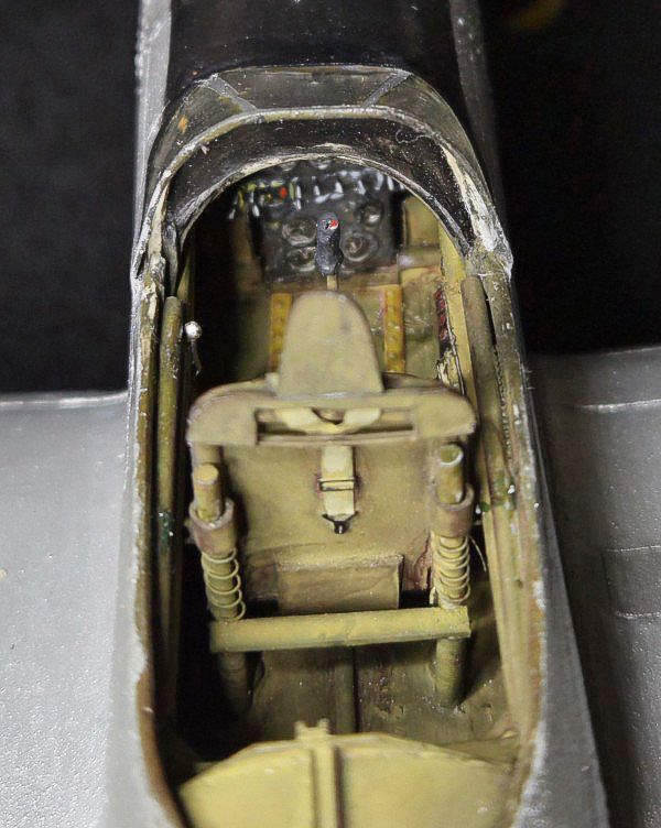
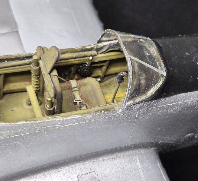
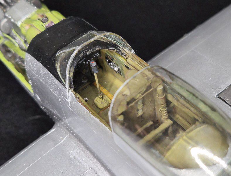
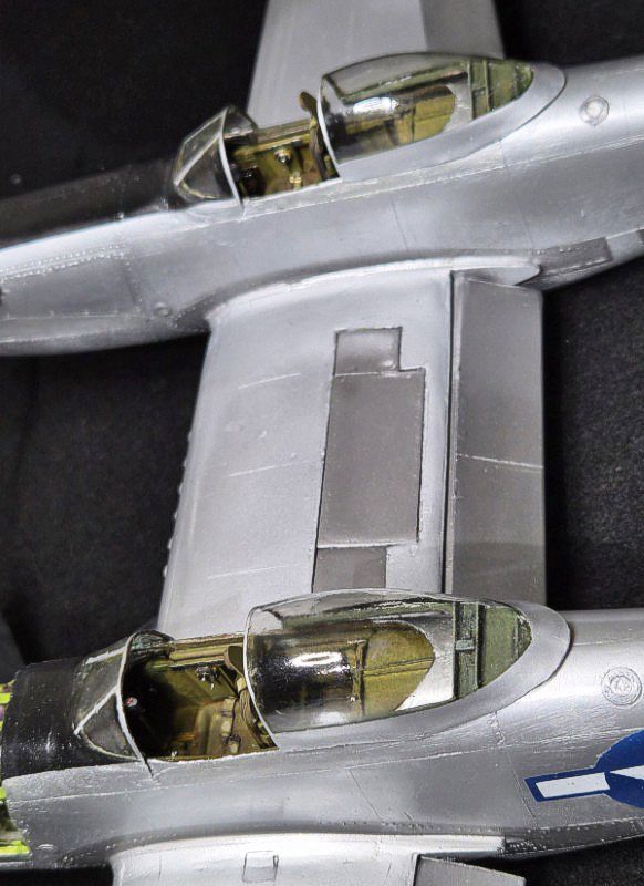
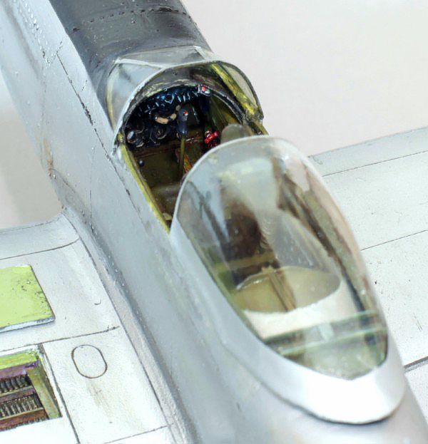
The cockpits were painted in Humbrol US Interior Light Green with black instrument panels. Dry brushing and washes were used to bring out detail. Once complete, the tubs were installed and the fuselage halves closed. The fit was checked to ensure the canopy would sit correctly over the cockpit openings.
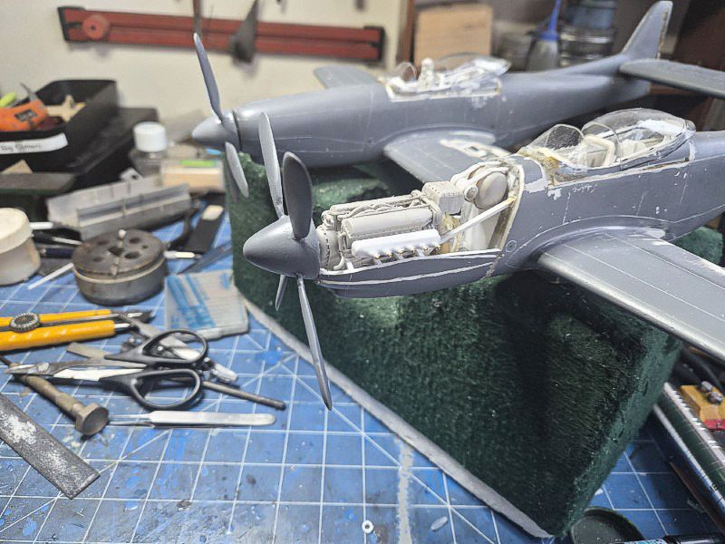
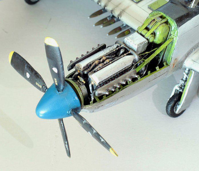
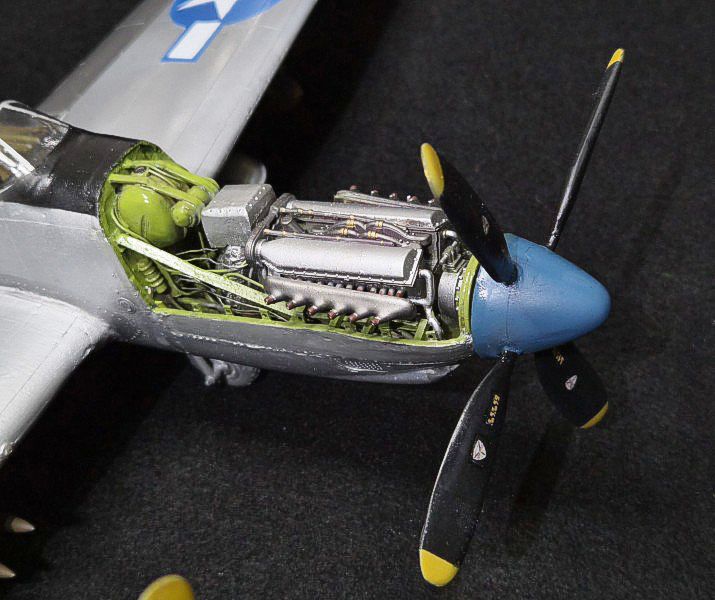
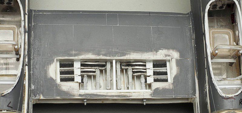
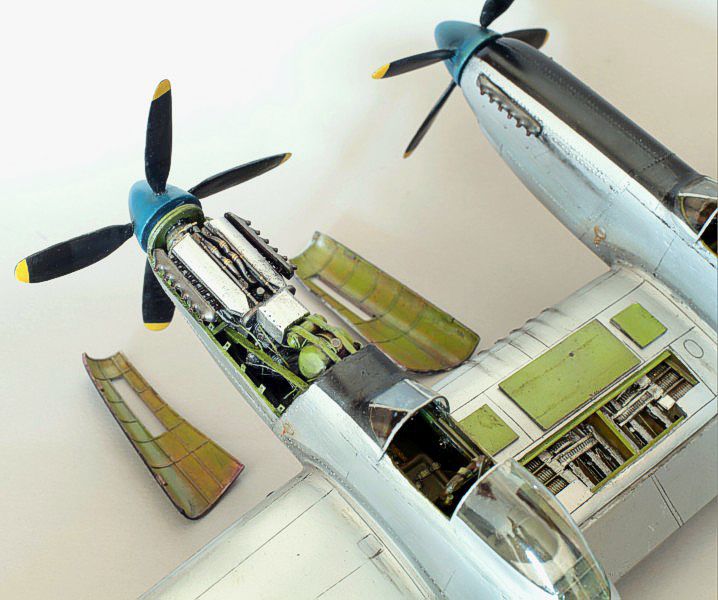
Engine Bay
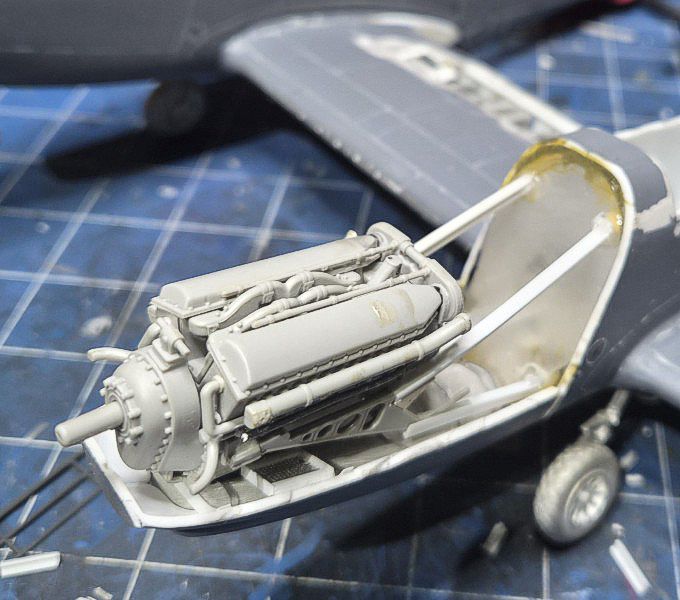
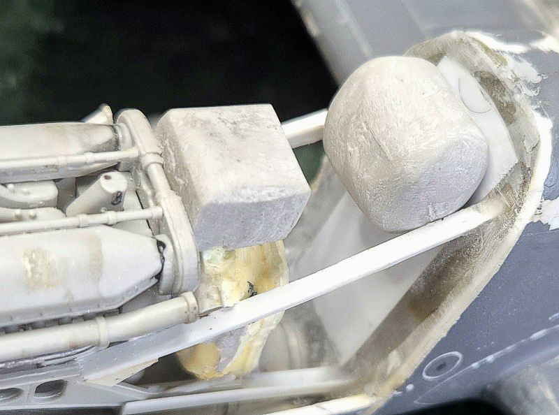
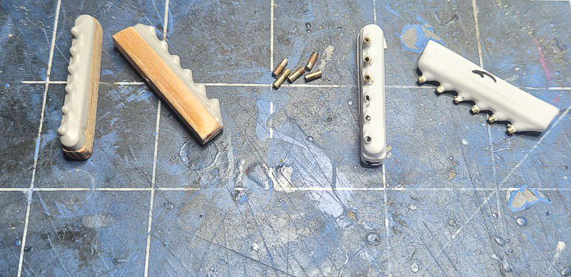
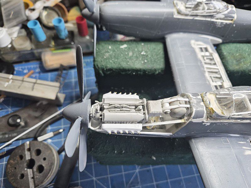
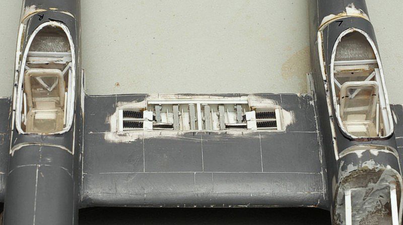
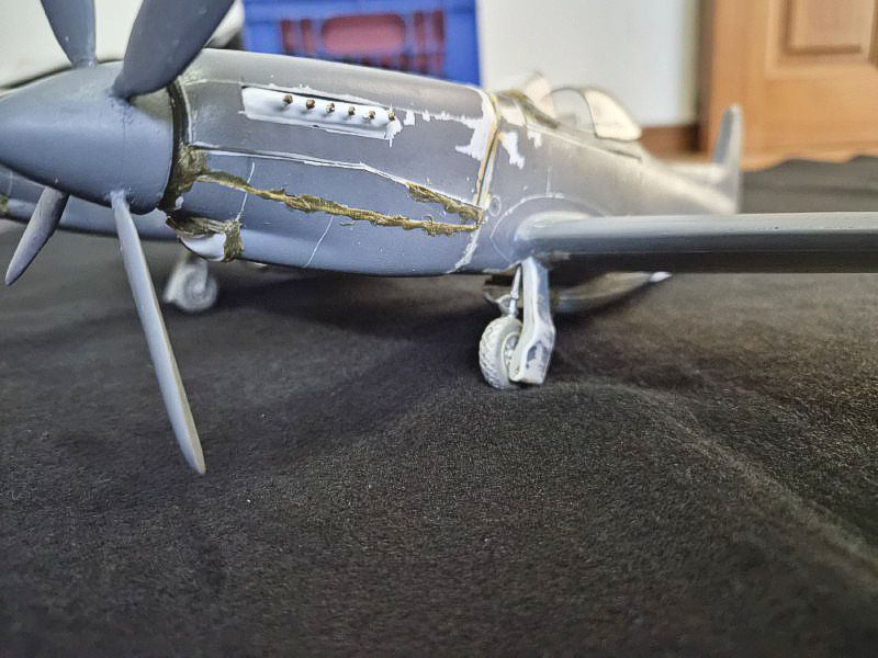
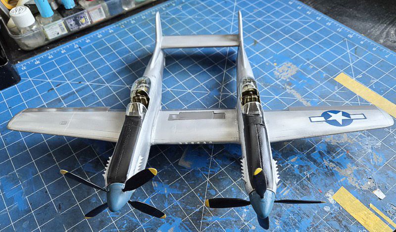
The engine bays were built up using layered styrene and kit-bashed parts to represent the Allison V-1710 installation (leftover from a Trumpeter P-38L). The basic structure was boxed in first, followed by the addition of engine mounts and firewall detail. Cylinders and accessory gear were shaped from rod and sprue, with wiring looms added using fine gauge wire. Other bits and stuff were cast from epoxy putty or resin. Not entirely accurate but pretty close.
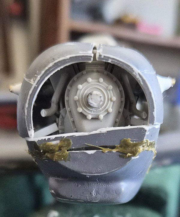
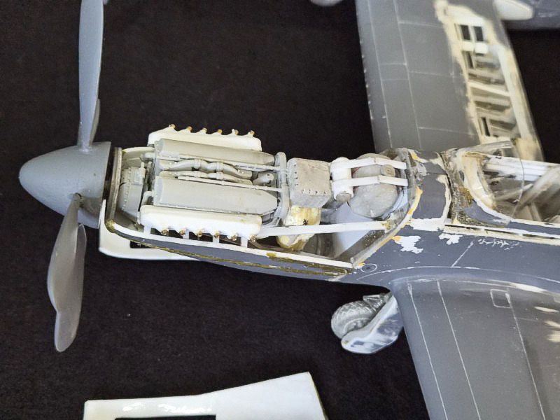
To offset distortion from the vacuform fuselage, the engine supports were built slightly oversized and trimmed to fit. The cowling interiors were reinforced and lined to accept the engine blocks. Cooling ducting and exhaust stubs were added next, based on available reference drawings.
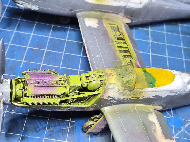
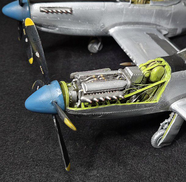
The engine bays were painted in a mix of metallic shades and weathered with washes to bring out depth. Once complete, the assemblies were test-fitted into the fuselage openings and adjusted for alignment. The final installation was deferred until after surface finishing to avoid damage during handling.
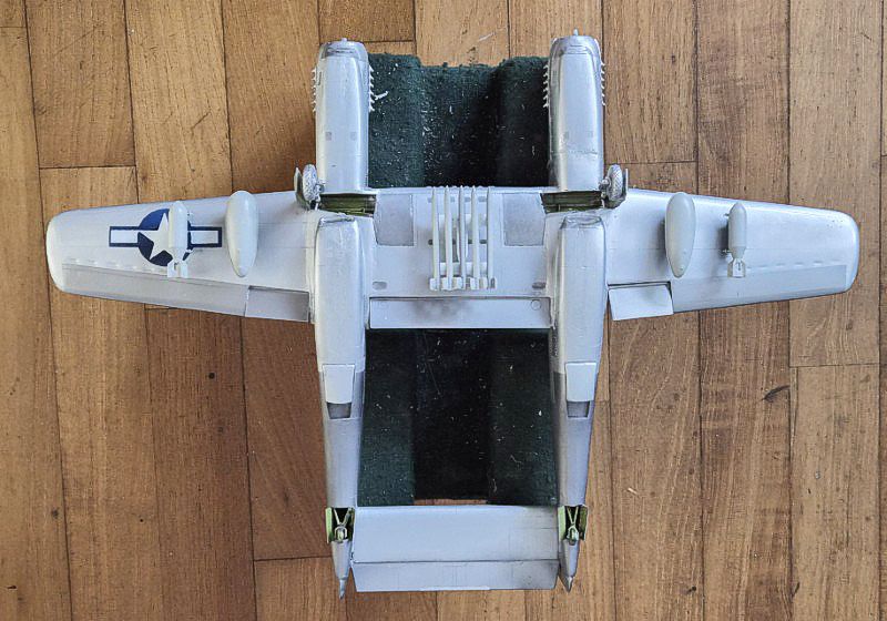
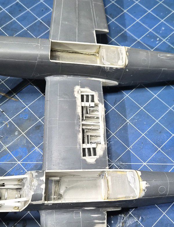
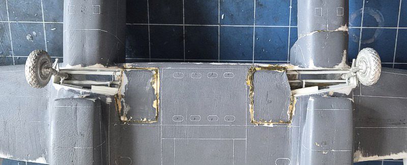
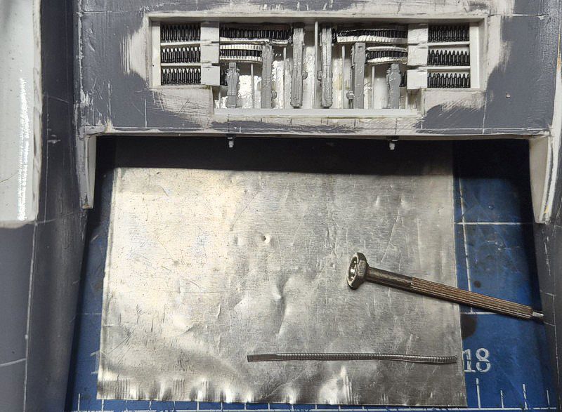
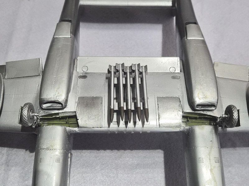
Undercarriage
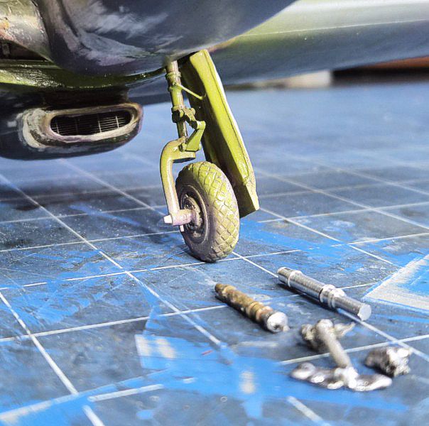
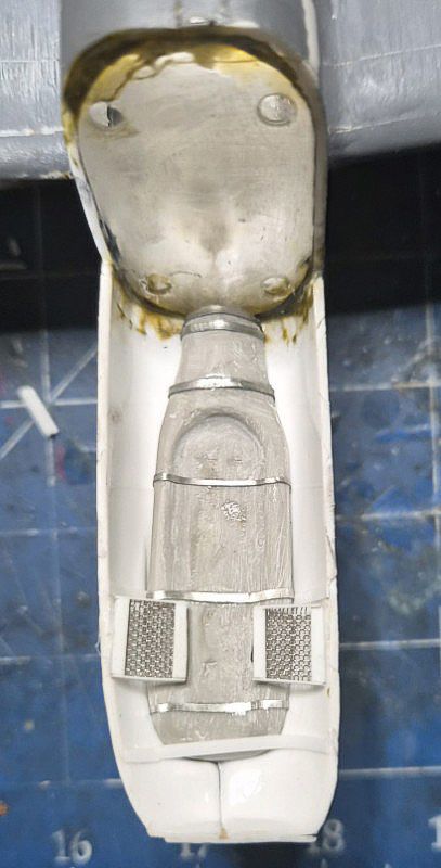
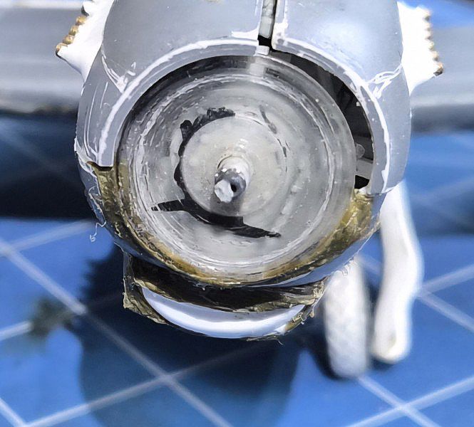
The undercarriage was constructed using a combination of kit-bashed parts and scratch-built components. The original white metal parts deformed from the weight. Soldering the brass struts to white metal forks ended in molten disaster. Finally, I machined aluminium main gear struts and fitted this to styrene forks and suspension and white metal wheels. The gear bays were boxed in with sheet styrene and detailed with basic ribbing and hydraulic lines.
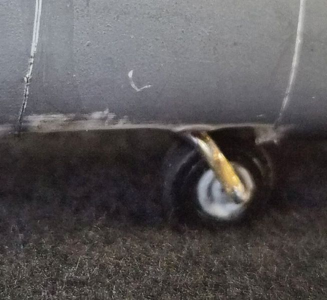
The tail gear was built similarly, with attention paid to alignment and clearance. Mounting points were reinforced inside the fuselage to support the weight of the model. Doors were cut from sheet and attached in the closed position for simplicity.
The assemblies were painted in aluminum and weathered lightly. Final installation was deferred until after painting to avoid damage. The model was test-fitted on its gear to confirm stance and symmetry.
Painting and Markings
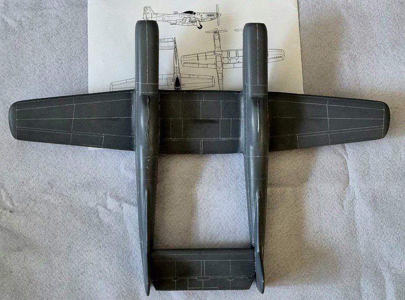
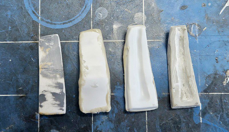
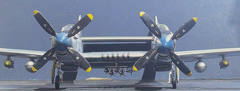
The model was primed with 2 coats of Rustoleum and sanded back to check for surface flaws. Panel lines were rescribed where necessary. A base coat of silver was applied using Tamiya Metallics, followed by masking for the anti-glare panels. These were sprayed in black.
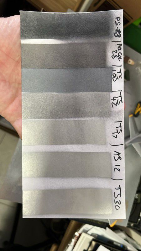
Paint shades were selected using test strips to match late-war USAAF finishes. In principle anything in the forward surfaces was puttied and smoothed over and given an aluminum finish. The trailing edges were in bare metal. Alclad II and K True metals were used for minor panel variation. Exhaust staining and oil streaks were added with thinned oil washes and pastel chalks.
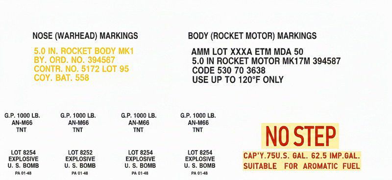
Markings were applied using a custom stencils and prints. National insignia, stencils, and serial numbers were positioned according to reference photos of the XP-82A prototype. Final sealing was done with a semi-gloss clear coat to unify the finish and protect the decals.
Final Product
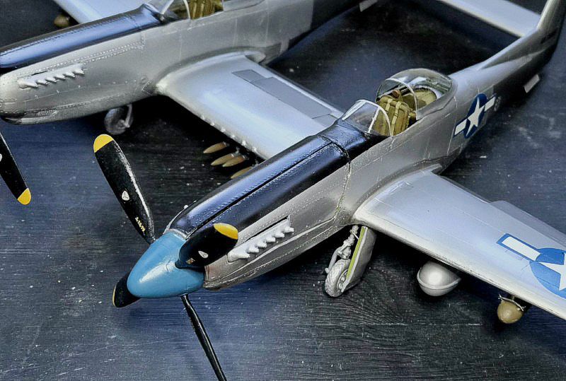
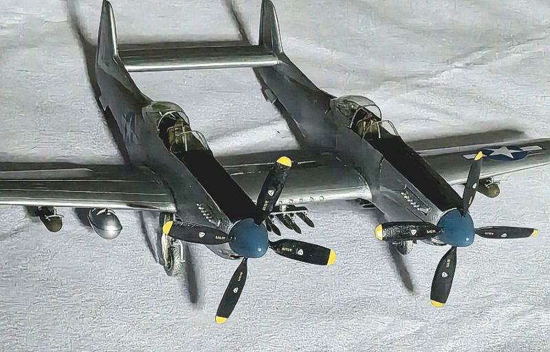
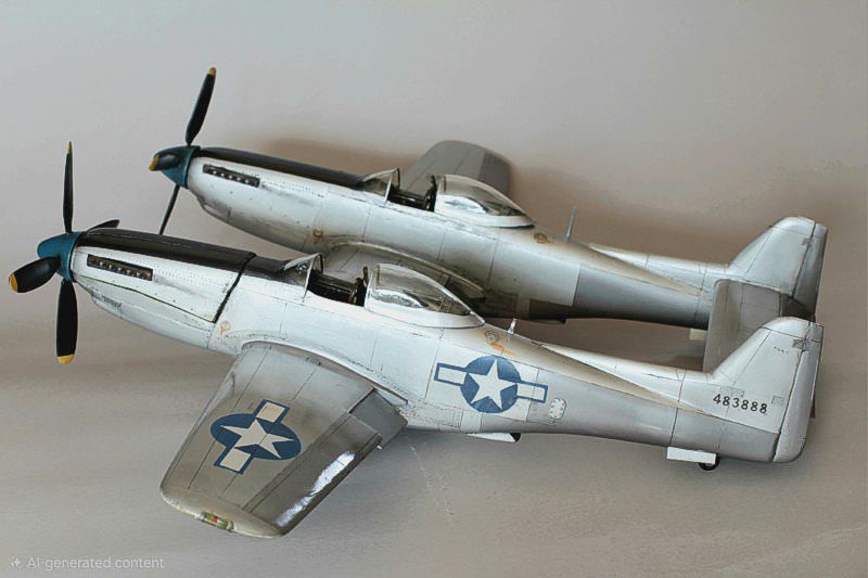
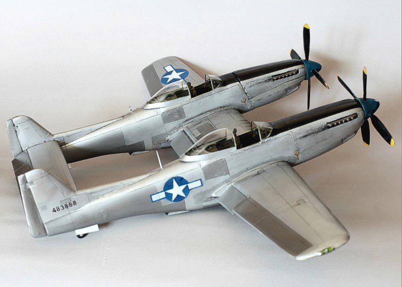
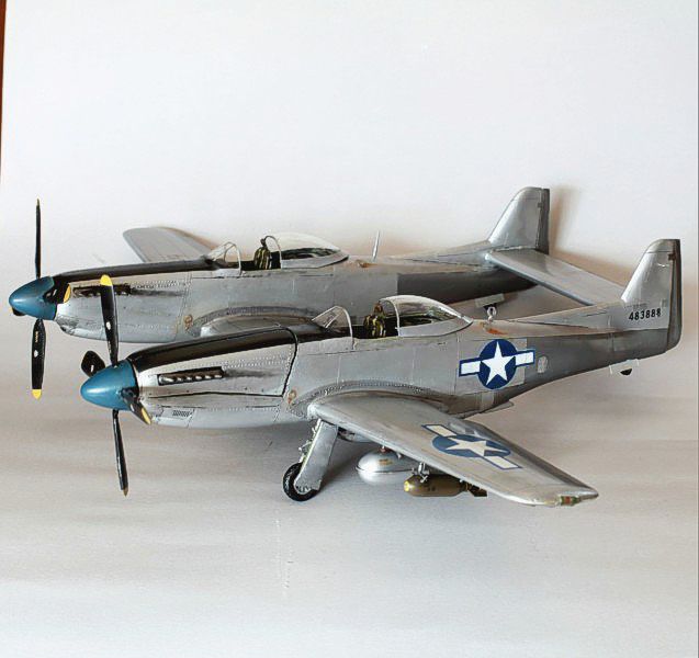
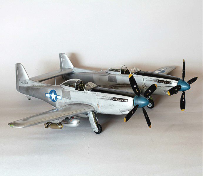
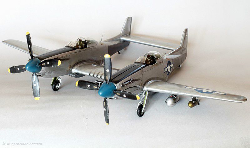
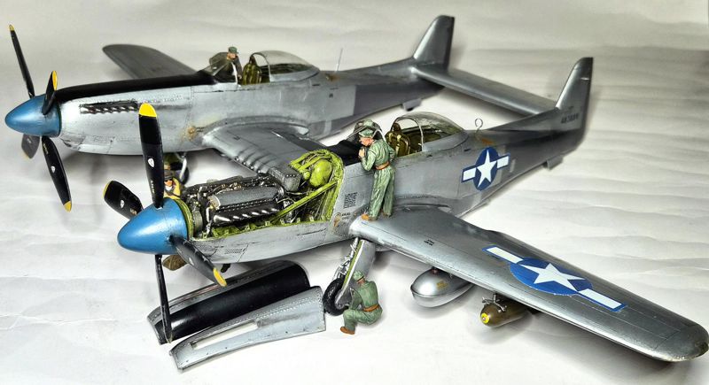
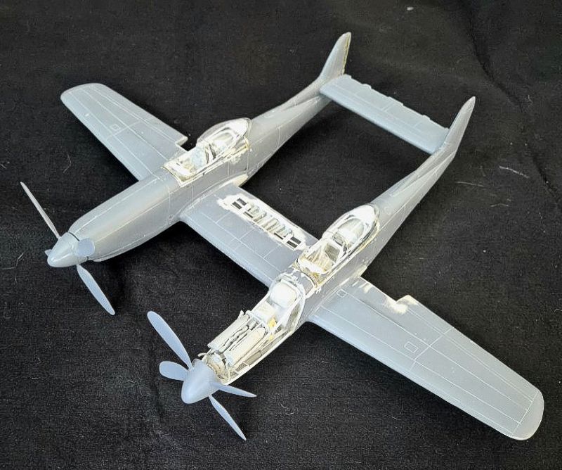
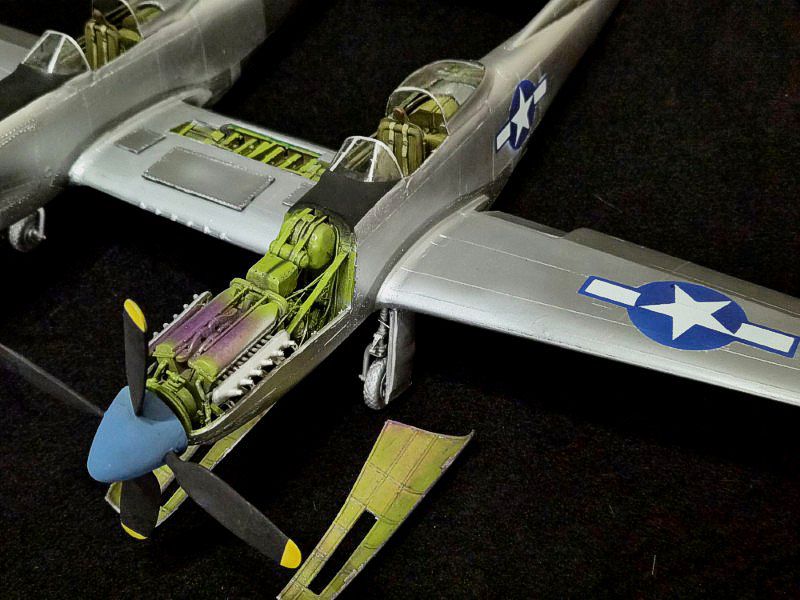
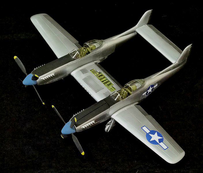
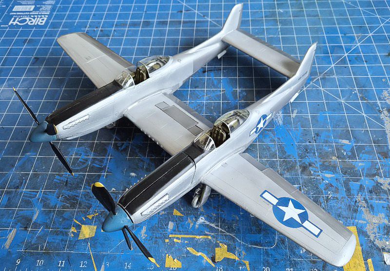
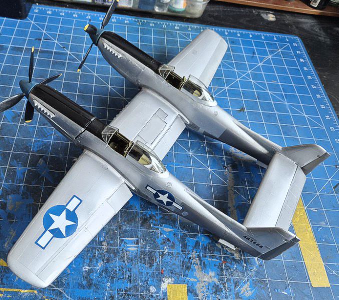
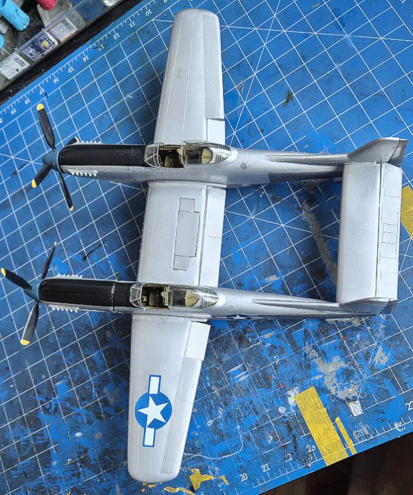
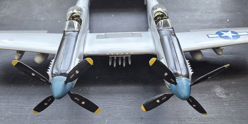
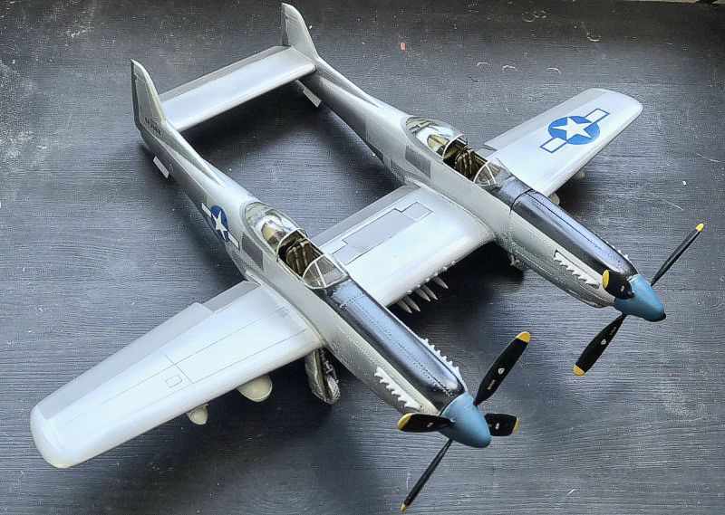
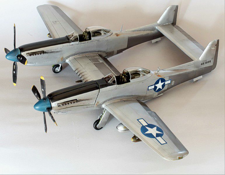
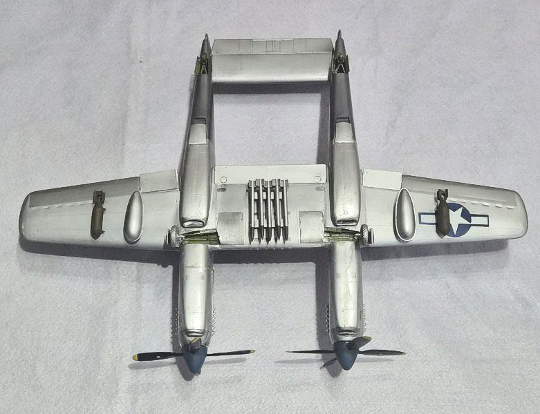
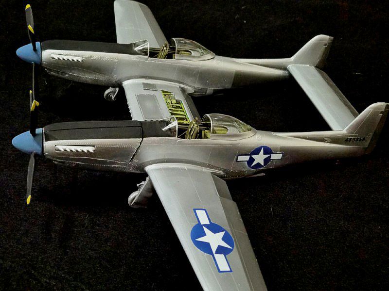
The completed XP-82A model presents a clean finish with accurate proportions and consistent surface detail. The twin fuselages are aligned and symmetrical, with the horizontal stabilizer sitting level across both booms. Panel lines are restrained and consistent with the scale. The cockpit glazing is clear and properly framed, and the undercarriage sits squarely with no visible sag.
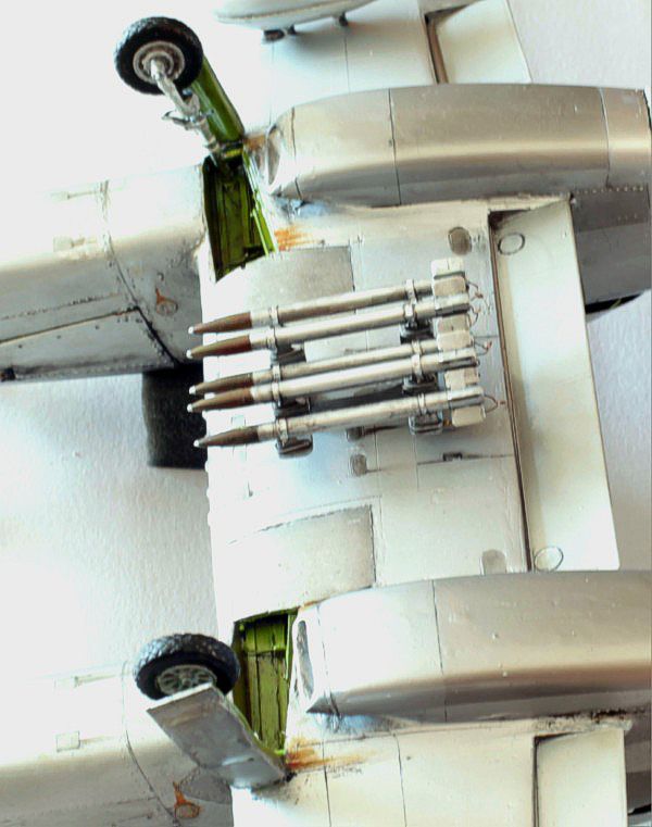
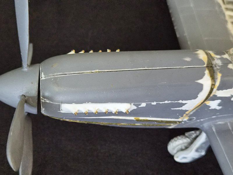
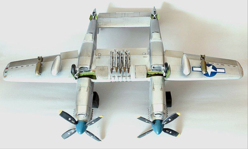
The engine bays and gun compartments are visible through open panels, showing internal detail added during construction. Paintwork is even, with tonal variation across control surfaces and subtle weathering around the exhausts and gun ports. Decals are well-set with no silvering.
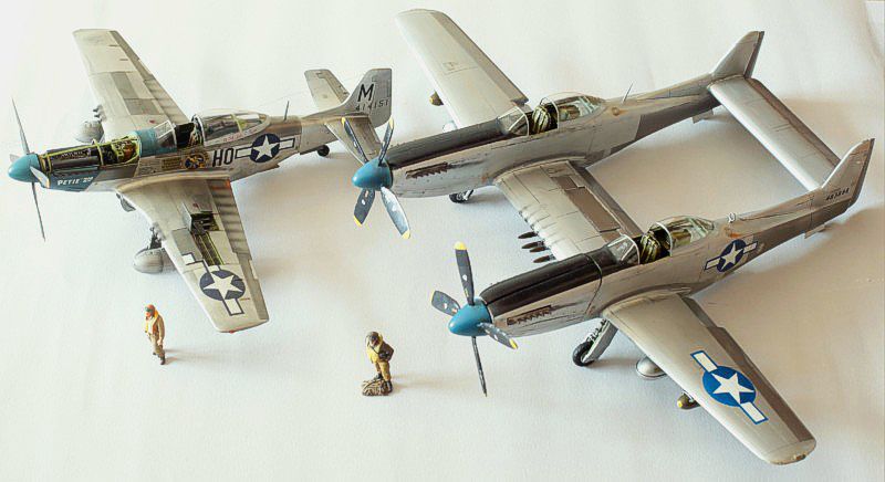
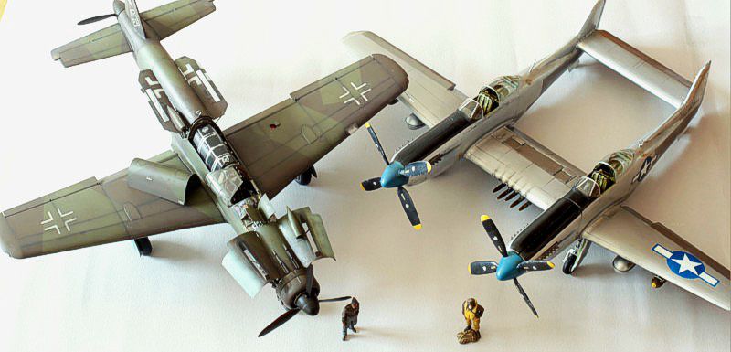
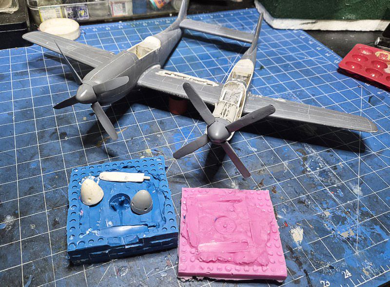
In the final comparison images, the XP-82A is shown alongside a P-51D Mustang and a Dornier Do 335. The Twin Mustang’s size and layout are evident—longer wingspan than the P-51D and a more complex silhouette than the Do 335. The juxtaposition highlights the XP-82A’s unique design and its place among late-war twin-engine fighters.
Summary
This build represents the Tigger Models 1/32 vacuform kit of the North American XP 82A Twin Mustang, the Allison powered prototype developed at the end of the Second World War. The kit provides the basic vacuformed fuselages, wings, and tailplane, but most of the detail work was scratch built.
The completed model has a wingspan of approximately 48 cm and a length of about 38 cm, making it a substantial presence in 1/32 scale. In comparison photographs with a P 51D Mustang and a Dornier Do 335, the Twin Mustang’s unusual twin fuselage layout and larger span are immediately apparent, underscoring its distinctive place among late war fighter designs.
© Suresh Nathan 2026
This article was published on Saturday, February 07 2026; Last modified on Saturday, February 07 2026