
Hasegawa and Revell 1/32 Messerschmitt Me 262
By Brian Cauchi
Introduction
There is no 'good' kit in this scale and anyone wishing to build an accurate model is in for a tough job. I have built both the Frog/Hasegawa (mine happened to be a very old Frog model which a friend of mine discarded) and the Revell Me 262A-la. The Hasegawa kit requires a large amount of work but the Revell kit requires a complete rebuilding for even in its basic element of shape, it is completely wrong. I however decided to take up the challenge and complete a highly acceptable model. Both kits were built at the same time. Scratch built parts common to both were simultaneously produced.
In both cases, the construction procedure listed below was followed:
- Installation of the front wheel well in one of the fuselage halves.
- Gluing of the fuselage halves together.
- Insertion of the cockpit tub into the fuselage.
- Installation of tail planes.
- Construction of wings and engines.
- Installation of wings onto the fuselage.
In order to further understand the work involved in building the models and the detail included, it would be advisable to have in hand at least some of the literature mentioned in the references section when reading this article. The various equipment and components added to the models would then be recognisable.
Front Wheel Well
The front half of the kit part supplied with the Hasegawa model is correct. However, the rear half should be round and in fact forms the cylindrical section in the centre of the gun bay. This flat portion was therefore cut off and replaced by a round plastic card section and new corresponding bulkheads. Internal frames and detail were added using plastic strip and copper wire. The whole wheel well was duplicated in plastic card and strip. The opening in the front fuselage was duly modified in the Revell kit to accommodate the new part. The kit opening was longer and the rear end was closed up using plastic strip.
Fuselage
The fuselage of the Hasegawa model was checked for accuracy against scale plans and also by comparison with the Dragon 1/48th scale model. No particular defects were noted and this helped in correcting the Revell fuselage. One half of the Hasegawa fuselage was taped to the Revell opposite half and a large number of differences were immediately apparent. Others were exposed by carefiil measurement of each section of the fuselage.
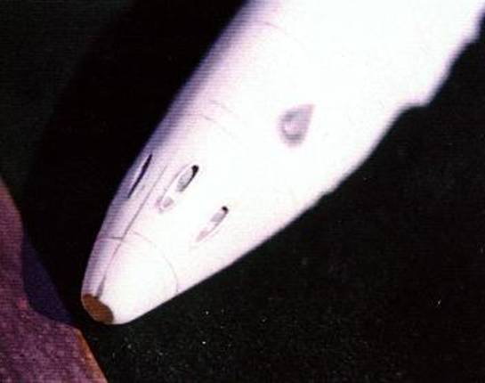
The overall length of the fuselage was found to be excessive. This was due to an elongated nose and an incorrectly shaped fin and rudder. The nose was cut by about 4mm, resulting in a gaping hole. The gun ports were reshaped and the fine, low, oval shaped edge produced from plastic strip. The tail fin was redefined and this necessitates filing away at the front portion. By shortening it chord wise, it is set back down the fuselage by about 1-2mm. The original rudder was retained and filed to the correct shape.
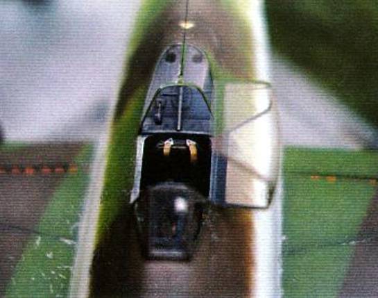
The cockpit area was modified using extra pieces of plastic to build it up to the correct shape and contour. This procedure was partly carried out before mating the fuselage halves together and partly later. The canopy edges were modified separately for the two sides prior to gluing them together.
The rear fuselage necessitated cutting out quite a bit of plastic to lower it down lengthwise from Omm at the base of the cockpit mound to about 4mm at the start of the tail. As in the case of the nose, a large lengthwise gaping hole results. This was only remedied after the fuselage halves were stuck together.
Following the above, internal detail on the fuselage sides was completed prior to gluing the halves together. This includes framing, cables, electrical boxes and the oxygen cylinder and pipes. At this stage, the fuselage sides for both models were glued together. Back to the Revell model. The new nose was built up with Mlliput and reshaped. The empty space above the wheel well was filled with lead shot and sealed in. The rear of the cockpit and fuselage were built up with plastic. This was sparingly used and then filed to shape. The Hasegawa canopy was continuously referred to at this stage to ensure a proper fit. The large gap left running down the rear of the fuselage was modified to accommodate a thick plastic strip. This was thoroughly glued in place and filed to shape.
Then came another shock! The Revell fuselage is even incorrect in cross section from the nose to the rear end of the cockpit. It was very tempting at this point to pour petrol on the kit and set it light. But once again, patience took over. A thick plastic strip was glued to each side of the fuselage running lengthwise along the defective section. Measurements were taken off scale plans using a vernier callipers and these were transferred onto the kit by carefully filing and sanding down the plastic strips and checking at lcm intervals. When this process was completed, the space above and below this strip was overfilled with Milliput. When bone dry, it was sanded down just enough to reveal the plastic strip. This served as a guide and the end result was even and symmetric. The filled in areas above and below the plastic strip were sanded to merge into the kit fuselage. With this finally and satisfactorily over, all raised detail was removed and fresh panel lines scribed.
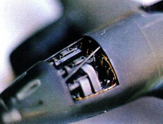
Gun Bay
Bulges were made out of plastic on the gun bay doors of the Revell model. The Hasegawa model has a detailed gun bay. All kit parts for this area were discarded except for the MkIO8's and ammo chutes. A completely new gun bay was built up from plastic nd wire. The centre section was already formed by the wheel well outer wall. Additional detail and gun mounts were added to this. The bulkheads and other areas were detailed as required. The gun bay doors' framing was made from plastic strip. Retaining clips were cut out and portrayed in the open position. In the end, most of the detail is covered when the guns and the ammo chute are put in. It's a pity but its all there.
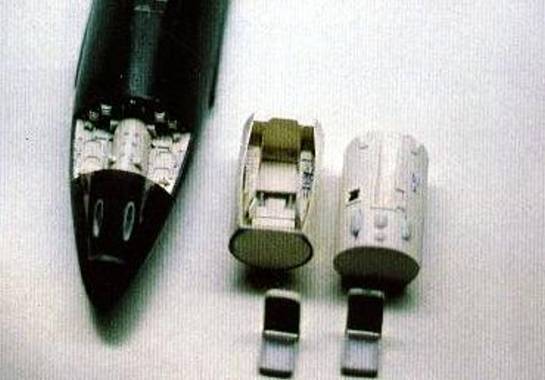
Cockpit Area and Canopy
The Me262 cockpit is housed within a tubular capsule. This was made of plastic card. The kits' cockpits were discarded. The basic cockpit tub consists of two circular ends and a rounded cylinder. Inside, were constructed the floor, side consoles including all controls and fuse board and the seat framework. Wiring and lever control connections were duplicated on the outside of the capsule. These would later be connected to wiring and levers located in the remaining space between the capsule and the fuselage sides.
Photo etched rudder pedals were used. All pipes and wiring were made from solder wire or copper strands. Clips for wiring were made from surgical blade covers (a soft metal). This technique was applied throughout the model wherever wiring clips were required.
The seat bottom, a deep 'pan' into which fitted the pilot's chute, was moulded off a Milliput 'male' mould. The back of the seat has a low padded cushion mounted within a thick frame. This was also made from Nfilliput. Photo etched seat belts were used. Internal framing and details were made from plastic strip and plastic blocks. All details such as as the oxygen bottle, electrical equipment, plumbing and wiring are located on the internal sides of the fuselage coinciding with the cockpit area.
The instrument panel was made from plastic card. Instrument bezels were made from thin slices of aluminium tubing. It was then painted in RLM66 and glass instrument faces for made with Crystal Clear. If I had to do it again, I would use etched bezels from any range such as Re-Heat. One would require a mixture of 1/32nd and 1/48 scale bezels.
One good feature of this model is that when both fuselage halves are mated together, the complete cockpit tub could then be inserted in place by being pushed up through the bottom. This allows for numerous dry runs to ensure a proper fit, the construction and painting of details with relative ease and the installation of the painted cockpit capsule at a very late stage thus avoiding unnecessary handling and damage.
The Revell canopy was discarded. The Hasegawa parts were used as the male mould. These were filled with Milliput so as not to cave in when put in contact with the hot acetate. Each part (a total of three) was then mounted on a brass rod which set into the Milliput. This would allow these to be held tightly in a vice until the hot clear acetate is stretched over them. Finally, the canopy framing was slightly lowered using 1200 gauge wet or dry sandpaper and the entire canopy polished using a rubbing compound. All clear canopy parts were then moulded.
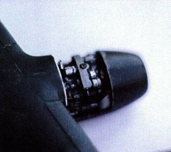
Engines
I decided to expose a part of the engine on the Hasegawa model. The top half of the forward portion of one of the nacelles was cut away. This panel was chosen since it was often removed for maintenance as documented in photographs. Framing was added to the panel as for the gun bay doors. All the components and wires were added on. The engine is a mixture of plastic and metal parts, mostly copper and aluminium tube and wire.
The engine nacelles of the Revell kit have the wrong shape. Besides being too short, the front and rear ends require heavy modification. About 4mm were removed from the rear end until the opening was of the required circumference. Details were redone in the proper location. The front portion was cast in NElliput using a mould made from the Hasegawa part. A plastic strip was glued round the lower half which had become too small in diameter due to the 4mm removed at the rear. The Nfilliput nacelles were then glued onto this and the remaining plastic. The resulting space was then filled in and sanded down to join the nacelle with the engine cover. This operation was similar to that carried out when correcting the fuselage sides where a plastic strip was used as a guide.
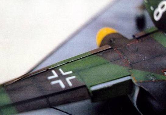
Wings
Raised detail was removed and fresh panel lines rescribed. Prominent fasteners on the underside panels were made using a filed hypodermic needle to produce neat little circles. The position and shape of the wheel well openings on the Revell model are totally incorrect. These were closed up with plastic card and re-cut to the proper size, shape and in the right position.
I had rightfully given up trying to find something accurate in the Revell kit. Another defect of the wings is that they are too broad. This could not be rectified, however since it would effect the engine shape and installation. I therefore decided to let this one pass by unnoticed by breaking up the wing outline. I did this by lowering the flaps and slats.
The flaps were cut out and filled with Mlliput. The front edge was then rounded off. Slats were filed and scraped off the kit and replaced with aluminium ones. Thin sheets of this material are used in printing. This can be sanded down to the required thickness. This material is easy to bend into shape and was in fact formed over the Hasegawa wings. The slats were then cut to size to fit the wing leading edges. They consist of three separate sections for each wing. Their guides were made from plastic card and fixed in place on the leading edge. The slats would be glued on to them at a later stage.
In both cases, the lower wing includes the fuselage centre section. Before joining the wings to the fuselage, the spars running through the wheel well were made. Wiring and pipes were also included at this stage. The Hasegawa wings were fixed in place. The big shock was yet to come! On trying to install the Revell wings, I realised that something was very wrong. The view seen through the wheel well of the different models was not the same. I then realised through measurement that the Revell wings were located too far back. In fact they had to move forward by about 5mm! Had I not already gone through all the trouble to rectify other major defects, this would have been the final straw. However, I gritted my teeth for what I hoped would be the last time and set to work. The front 5mm of the lower wing centre section was cut off until they would be properly positioned. These were then glued in place. The resulting gap was filled in using a thick piece of rectangular section plastic. The excess plastic was filed and sanded down. More Milliput (bless its malleable heart) was used to fill gaps to the front of the aircraft and in the joint between the wings and the fuselage.
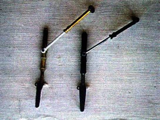
Wheel doors and Undercarriage
The Hasegawa wheel doors were accurate in shape. These were detailed and thickened using plastic card. Another set were made for the Revell model. The inner wheel cover actuators and hinges were made from metal tubing and wire. The tyres were filed down to give a weighted look. All undercarriage legs and actuating mechanisms are scratch built using copper and aluminium tubing. Besides detailing these parts, metal was used to give strength and stability.
Painting
Areas such as the cockpit interior, engine and wheel wells were painted during construction. After painting in the appropriate colours, a thinned oil paint (burnt umber) wash is applied. The oils are thined down using white spirit. After a couple of days, when the oil paint is properly dried, all parts are dry brushed with the appropriate lighter shades. This greatly enhances all details. The cockpit interior and gun bay was finished in RLM66. The main wheel well was finished in various shades of aluminium. The gun bay and engine covers were also painted in RLM66 internally.
Now for the models themselves. All painted areas such as the cockpit, wheel wells and gun bay were carefiilly masked. For the Hasegawa kit, the engine and gun bay covers were fixed with some Crystal Clear in the closed position. This ensures a continuation of the camouflage pattern during painting.
I use cellulose thinner throughout when painting. The following procedure is standard practice used in all my models. The models are first given two coats of automobile grey primer filler. This is then sanded down to a perfect smooth finish with wet and dry 1200 grade sandpaper revealing any construction defects. These should be rectified at this stage. Painting then moves on to the camouflage colours. All these were mixed specifically for the job using Humbrol enamels. The right shades were arrived at with the help of the IPMS colour guide and a fan deck of FS colour chips.
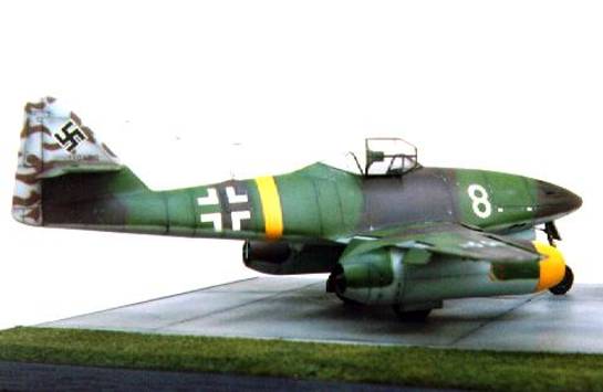
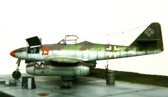
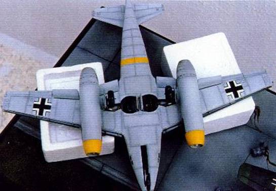
The first colour to be painted was the underside RLM 76. This was run up to the cockpit on the Hasegawa model. It was sprayed on the underside and tail of the Revell model. When painting, one moves into another realm of modelling and starts to forget all the trouble encountered during the construction phase. From now on, the kits are no longer Hasegawa and Revell but Red 13 and White 8.
Painting procedure for each colour is carried out as follows. The proper colour is used throughout and left to dry. A lighter shade is then mixed by adding white. This is heavily thinned and carefully sprayed onto the centre of each panel, along leading edges and at any other prominent area most likely to be effected by the air rushing past. The effect is slowly built up each time adding on a thin layer of paint.
A darker shade of the colour is now obtained by adding a touch of dark grey. The heavily thinned paint is then applied with the airbrush setting at the finest. This is applied to panel lines and along the fuselage in the direction of the airflow in areas effected by gun fire or exhaust. The result of all this is a contrasting three tone effect enhancing panels and the aircraft detail.
Back to the original accurate shade. This is greatly thinned down and all the painted area sprayed lightly. The different shades merge until contrast is more subtle. This process should be repeated as necessary. The resulting contrast can be controlled. The more weathered the model, the more contrast should be apparent between the shades. Any battle hardened aircraft should have very obvious contrasting shades.
The bright medium green, RLM83 was then applied. The same procedure followed except that lighter and darker shades of the green were achieved by mixing with lighter and darker green respectively. I avoid using black and white since some colours change when mixed with these shades. Finally, the Braun violet RLM81 was applied. Flaps, slats and wheel door covers were separately painted. Painting is only complete when you think that the models look right. Painting becomes more difficult when photos of the real aircraft are available and camouflage is to be duplicated. In fact, my Red 13 fuselage colours were applied at least 5 times before I was satisfied that it looked like the photo! Coats of paint should always be thinned down to avoid losing surface detail. Last to be painted were the yellow (RLM 27) engine nacelles and fuselage band on White 8 and the red nose (RLM23) on Red 13. Even these are sprayed using the three tone technique.
At this point, the finished paint is rough. The model is now given several (5 to 7) coats of thinned gloss varnish (60% thinner - there is no exact formula but the mixture has to flow very easily). The varnish used should be perfectly clear. I usually use the Revell varnish. This is left to dry for at least 48 hours. All panel lines are then given a wash with oil paint (burnt umber) thinned with white spirit. The paint should be thinned enough to allow easy flow of the paint along the panel lines. At this point, there will be overspilling of the paint from the panel lines but his will be dealt with later. The wash is left to dry for at least four days. The whole model is sanded down again using the wet and dry 1200 grade paper. This process should be carefully and lightly carried out using previously used sandpaper. This will allow for gradual removal of surface defects and the excess wash from the model. The result should be a very smooth, defect free surface.
The decals are applied next. Those supplied with the kits were deteriorated due to their age and had to be discarded. National markings are from Mcroscale decals. The Werk Nummers are of the rub on type. I was lucky to find the right size and style. However, I could not find decals to fit the size and type of white 8 and red 13. A template was made for the white 8 and this was sprayed on to the model. The red 13 was hand painted onto a clear decal sheet. The black outline was partly obtained from a rub on sheet of numbers and lines and partly hand painted when it follows a curved outline.
When all the decals are in place, coats of thinned down gloss varnish are sprayed over them and their immediate surrounds. These are left to dry and sanded down smoothly. This process is repeated as necessary until the decal edge is eliminated and merged into the model finish. When this process in completed, the decal outline should be invisible when viewed against the light. As an aside, this technique may be used to make good any defects which could have gone unnoticed up to this stage such as minute scratches, sink marks and the elusive joint line.
Details such as aerials, pitot tube and undercarriage are all fixed in place. I like to fix these parts at such a late stage to avoid countless handling accidents since the model is sanded down at least three times in the process described above. One cannot sand the whole model down satisfactorily if certain items are in place.
I love the next stage. More weathering in the form of chipping and gun and exhaust stains are put on the model. The paint chipping and scratching is painted on using a 00 brush and Humbrol silver. This stage can enhance or ruin the model. All paint chips and scratches have to be finely applied. One must study as many photos as possible to get this right. Chipping is applied to cockpit edges, wing roots, foot and hand holds and all the panels usually removed many times during routine maintenance, refuelling and rearming. When dry, they are gently sanded down to merge into the paint. This removes most of the shine and excessive marks, makes them more subtle and they will not be immediately apparent from certain angles. A mixture of burnt umber, burnt senna and black oil colours are mixed and thinned down this time using cellulose thinner. These are gently airbrushed to simulate gun and engine stains. If sufficiently thinned down, the effect may be built up gradually. Thanks to the coats of gloss varnish applied previously, any mistakes at this critical stage can be rectified by simply sanding gently away. Only the varnish is removed and the model colours are not effected.
When this is complete and all defects have been remedied, a couple of coats of thinned matte varnish are sprayed over the whole kit for a good even finish. Once again, I prefer the Revell matte varnish since this is absolutely clear and does not yellow.
Before installing the canopies, the revi gunsight was located in place. As with most other parts, this was scratch built. The final stage is the canopies. These were trimmed to shape. It is good to mould a few extra parts since there is always the inevitable scratch or imperfection or one might trim a bit too much. Clear decal sheet is sprayed with RLM66 and the camouflage colours. Thin strips of decal are then used to frame the canopy, RLM66 on the inside and the camouflage on the outside. The Armoured glass was made from a thick piece of clear plastic. This was edged with RLM66 painted decal strip. The canopy is then fixed in place using Crystal Clear. The middle segment of the canopy has a handle and this was fixed on at this stage. The canopy retaining springs were made from thin copper strands and glued in place. White 8 also had its headrest fitted. Red 13 did not have this headrest installed as may be clearly seen from photos. This was probably a personal decision of the Heinz Bar who preferred to have uninterrupted vision than the armoured headrest.
Should you follow the above, you will eventually be either locked away in some looney bin or else be the proud owners of two 1/32nd scale Me 262s, the pride of your collection!
© Brian Cauchi
This article was published on Wednesday, July 20 2011; Last modified on Saturday, May 14 2016