
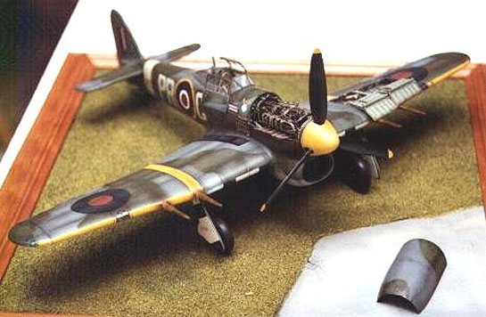
Revell 1/32 Hawker Typhoon 1B (Car Door)
By Brian Cauchi
Introduction
The following write up is based on the Revell kit. At first glance, when compared to other products from this manufacturer of the same era, the kit seems to be superior, having greater detail, a better fit and more accuracy. However, being a detailing freak, I still put in lots of work. As I progressed, the defects and areas requiring considerable amounts of work became apparent and the conclusion is that my dream of building a 1/32nd scale kit of a World War II fighter with relative ease to the standard I desire has yet to be achieved. I hope to satisfy this wish during the coming millennium. Even if one decides to build a standard kit without exposing any hidden parts, the main visible areas such as the wheel bays and cockpit require a mayor reworking.
The sequence I followed when building this model was as follows:
- Scribing the whole kit.
- Detailing the engine.
- Detailing the cockpit.
- Detailing the fuselage halves and tail wheel area.
- Gluing the fuselage halves together with the engine and cockpit assemblies included.
- Installation of tail planes.
- Detailing of wheel bays and gun bay.
- Installation of wings onto the fuselage.
- Painting and Decals.
- Canopy, undercarriage, flaps and other final details.
In order to further understand the work involved in building the model and the detail included, it would be advisable to have in hand at least some of the literature mentioned in the references section when reading this article. The various equipment and components added to the models would then be recognisable.
The first step taken after opening the box and inspecting the kit for its general accuracy was the very laborious and tedious task of scribing the whole kit. When scribing, the kit panel lines are retained as a guide where accurate until the new lines are scribed. Missing panel lines are added on as necessary and any inaccuracies corrected. Each scribed section is then sanded down with 1200 gauge wet sandpaper to remove the raised panel lines. This operation, in my opinion is a necessary waste of time. Scribing the kit takes up a lot of time and you have nothing constructive to show at the end. Your effort only shows up when painting the model.
The most boring stage in modelling is now over. Let the fun begin!!
CONSTRUCTION
Engine
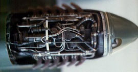
The Napier Sabre 24 cylinder engine used on the Typhoon was truly an awesome monster to behold and to model. It is a very complicated piece of machinery which however looks as powerful as it really was. The kit comes with a removable side panel which reveals a highly inaccurate engine. I decided to expose the upper half of the engine, uncovering as far as the exhaust pipes. The removable panel was therefore fixed in place and the top half of both fuselage sides cut off. The two removed pieces were then glued together to form one whole cover. Although I always try to detail the engine of any of the models I build, exposing too much of it may ruin the streamlining and look of the aircraft. I therefore settled on the upper half, retaining the cowl cover and modifying it so that it may fit in place if so desired. Apart from these considerations, there are numerous photos showing Typhoons and Tempests with this panel removed. It is therefore a realistic state in which to depict the model.
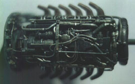
The kit's engine was assembled as per instructions, including the radiator housing. The first modifications to be made were to the cylinder head tops and the top left and right sides of the engine. These were covered with plastic card to form two box-like structures. I then replaced the cylinder head tops (junkheads). These were made from aluminium tubing cut into thin slices and pressed to shape. Sparking plug inserts for the high tension leads were made from thin plastic tubing. The main components on the top part of the engine were then added. These include the starter, hydraulic pump, compressor, magnetos, crankcase breather and distributor. They are basically box or cylindrically shaped components and were all made from plastic tubing and bits of plastic.
The next main step when constructing the engine was the replacement of the exhaust pipe ends. The kit comes with circular exhaust stacks. These should be oval in shape. These were made from aluminium tubing which was flattened to shape and filed down to decrease their thickness. The part of the exhaust stacks closest to the engine were retained and only the ends replaced. These were press fitted onto the plastic stubs and then glued so that they would not easily fall off. A bit of filler completed the job.
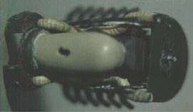
Since I did not know exactly what parts of the engine would be visible through the gap between the engine sides and the fuselage and also from the radiator cooling flap, I proceeded with duplicating an amount of detail on the underside of the engine which was mostly superfluous. This included pipes running from the coolant tank to the rear of the engine, engine bearers and coolant pipes running from the radiators to the firewall. These were made from plastic tubing bent to shape and covered with strips of masking tape which when overlapped will simulate pipe lagging.
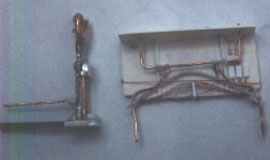
Now for the main air duct. The size and shape of the duct supplied in the kit is completely wrong and this was rebuilt from Milliput. This has to be much larger and protrudes prominently from the underside of the aircraft. A slot was also made through its bottom to accommodate the radiator flap actuating piston which passes right through it. The radiator itself as supplied is very small. This was cut up and widened as shown. The two sides were used and the rest of the unit was built up from plastic. The front part of the radiator was extended to fill in the whole opening in the fuselage. The central portion was opened up and the annular air intake constructed from plastic tubes.
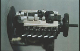
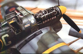
>Details were then added on the firewall. These included bits of equipment, pipes and wires and also the fastening eyes for the engine covers. Engine bearers running from the main horizontal supports to the firewall were also constructed. Due to the complexity of the engine and the vast amount of pipes and wiring involved, I decided to paint the basic engine before going on to add further detail.(plate 2)
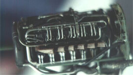
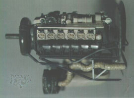
Additional layers of pipes and wires were added on progressively, each time painting the completed details before adding on more and partially obstructing the previous ones. This is the only method which allows for the proper painting of all the various details included in the engine. In order to avoid disappointing accidents where pipes or wiring would be knocked off, the ends of all these were glued to the various locations on the engine in pre-drilled holes. Final repeated washes and dry brushing completed the engine. The last detail to be added on was the circular bracket passing over the top of the engine to which are attached another set of fastening eyes for the engine fuselage cover. Fastening eyes were made from small blocks of plastic which were then drilled. Clips for wiring and pipes were made from surgical blade covers. These are made from a soft malleable material which is easily cut into very thin strips and wound around the pipes and wires to simulate clips. This technique was applied throughout the model wherever wiring clips were required.
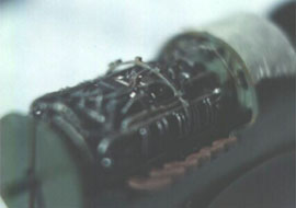
The next step was to fit the engine into its bay in the fuselage. After adding on all the details, it immediately became apparent that both the forward fuselage sides and the engine top cover need to be sanded down and made as thin as possible. Then and only then will the engine fit properly in its place and one may also cover it using the kit's part which also requires a lot of sanding and filing to render the plastic as thin as possible without disintegrating. As soon as the engine was fitted in the fuselage, it became evident that any detailing works below the exhaust pipes are completely lost from view.
The monster was therefore vanquished. On to the fuselage.
Fuselage
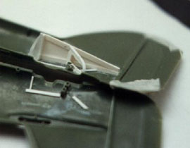
The fuselage was checked for accuracy against 1/32nd scale plans and enlarged 1/72nd scale plans. No particular defects were noted and I next proceeded to detail the interior. The tail wheel area was detailed using plastic card. Although most of this detail is not visible, a bulkhead and enclosure were constructed together with guide rails along which the tail wheel slides to be retracted. The actuating piston for the wheel retraction was ignored since this would not be visible through the tail wheel opening.
The cockpit area of both fuselage halves was detailed next. Internal framing was then made from plastic strip. Wiring and other items of equipment were then added onto the fuselage halves in the area just beneath the windshield. These were made from bits of plastic, and copper wire. I find that the brass frets from photo etched sets come in handy when producing fine handles, clips, levers and retaining brackets. Such fine detail can be produced which would be impossible to make from bits of plastic since these would be too thick and would look very unrealistic. The thin, easily bent pieces of brass, on the other hand are excellent for such fine detail. Thus, the fuselage halves were complete and set aside. On to another major task, the cockpit.
Cockpit Area and Canopy
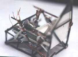
The Typhoon cockpit, like all Hawker fighters of the time, was built around a tubular structure. All items making up the cockpit such as the instrument panel, side consoles and equipment, wiring and even the seat and armour were then attached to this tubular supporting framework. When building my model, I duplicated this framework and then fixed all the cockpit accessories onto it as in the real thing. This allowed me to end up with a complete detailed cockpit which I then fitted into the fuselage.

Only the side framing is supplied with the kit as two separate parts. These are meant to be fixed onto the fuselage sides. These were in fact used but joined together with other plastic tubing to form the whole cockpit support structure. At this point, it is imperative that the fit of the cockpit structure within the fuselage is constantly checked so as to leave space for the wheel wells when the wing structure which includes a complete centre section in fitted onto the fuselage. The tubing was pinned and glued together for additional strength. The kit cockpit floor is one complete part. This was in fact two long strips forming foot rests in line with the rudder pedals. They were cut out from the kit part and fixed to the tubular floor supports. The rudder bar and pedals were produced from copper wire and plastic. Wiring was then made from copper and secured with clips to the cockpit framing. As mentioned previously, clips were made from surgical blades' packets which are made from a very soft thin sheeting.
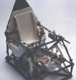
The left hand side console was constructed next. This includes various switches and controls which were made from copper wire. The seat height adjustment lever and foot pedals for operating the brakes were also made at this stage. The left hand side details were produced next. These include the trim wheel and throttle controls. All these accessories were made from plastic and brass. The seat mounting brackets were also included at this stage. The pilot's rear armour plating was cut out from plastic sheet and glued in place to the tubular frames behind the seat.
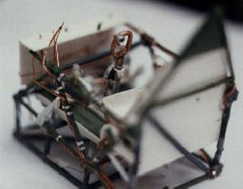
The next step was to construct the control column, pilot's seat and front lower bulkhead. The control column was scratch built from copper, plastic and aluminium. The seat supplied with the kit is completely inaccurate and this was discarded. A new seat was built out of plastic card and copper wire. This was made to fit into the supporting brackets already installed on the cockpit framing. The lower front bulkhead was also constructed from plastic sheet. Details on this included plumbing and wiring and also a number of fuse boxes. It is sad to think that once installed inside the aircraft, most of this detail did not show. However, during the construction stage, I am never too sure what will show so I always include that extra bit of detail.
The instrument panel and side consoles were made from plastic card. Instrument bezels consist of thin slices of aluminium and copper tubing. Pieces of plastic and brass were used to complete the details on the consoles. These were then sprayed in at least two shades of grey and black. The instrument faces were then painted by hand using a 00 brush and copying details off a photograph. Glass instrument faces are made with Crystal Clear. If I had to do it again, I would use etched bezels from any range such as Re-Heat. One would require a mixture of 1/32nd and 1/48 scale bezels.
The separate assemblies (cockpit framing, seat, bulkhead, control column and instrument panel) were individually painted. When dry, the whole cockpit was assembled. Photo etched seat belts from Teknics were painted and fixed in place. As an aside, I must say that these are made of stainless steel and are very difficult to bend and keep in place. Brass is a much better medium to work in and it is far more possible to obtain a realistic end result since the steel tends to remain stiff and not hang loose. The compass and its supporting frame were scratch built from plastic tubing, aluminium and brass fret.
The next step involves the gluing together of the fuselage halves. The Typhoon takes shape. It finally begins to look like an aircraft after hours of work.
Fuselage
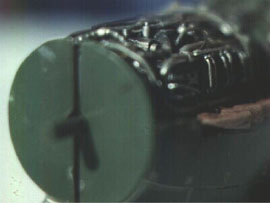
The engine assembly was installed in the fuselage. This together with the cockpit and tail wheel assembly were fixed to one of the fuselage halves. Both halves were then glued together. An extra plastic circular piece was added on the nose of the aircraft behind the propeller spinner. This was then sanded down until its surface was at right angles to the central axis of the aircraft, a defect which became apparent when both fuselage halves were fixed together. The propeller shaft forming part of the fuselage was replaced by a copper tube of larger diameter. An aluminium band complete with fixing eyes for the top cover was fitted to the front end just behind the spinner. This was made from sheet aluminium which I like to use in such cases. Sheet aluminium may be sanded down till very thin and then cut to shape. Fastening holes were then drilled to match with the cowl cover fasteners' position. The cowl cover was also modified to fit snugly over the engine and flush with the rest of the fuselage. Strips of plastic were added to its edges and then sanded down. These made good any alignment defects and also made up for the amount of plastic lost to the thickness of the saw blade when the cover was cut away from the rest of the fuselage.
The fish plates supporting the tail section of the Typhoon were shown as raised lines on the kit. These were cut out from thin plastic card using an Eduard template and stuck in place on the kit. They were then sanded down to a very thin profile.
The radiator cooling flap on the lower side of the cowling was cut off and replaced by a thin plastic sheet which was fixed in the open position. To this was attached a brass bracket bearing the flap actuating piston, the latter made from copper wire passed through a length of brass tubing. This piston passes through the slot prepared in the air intake which is made from Milliput as explained above.
The last modification on the fuselage concerns the tail section. The fin was cut off from the rest of the fuselage. A piece of plastic rod was glued on to its leading edge so that this was later fitted on in a displaced position. I was careful not to ruin the detail on the fin when cutting out and sanding down the rod on the leading edge. The actuators for the fin and trim tab were made from copper wire and fuse wire respectively. Fuse wire may be bought to different thickness. This is easily cut and bent into shape.
On to the wings. What's a plane without its wings!!
Wings
Wing installation commenced from the lower section. This had already been scribed beforehand and prominent fasteners on some of the underside panels were made using a filed hypodermic needle to produce neat little circles. At this stage, I also cut out the landing flaps which I wanted to detail when in the lowered position. This section of the kit had to be modified in the air intake area to fit around the greatly enlarged intake. It was therefore carefully cut and sanded till the exact fit was obtained. Only then could this be fixed in place. One very awkward area to finish neatly was the joint of this section to the fuselage in the radiator area. This was eventually duly filled and sanded down to make the joint invisible but it took quite an effort to work between the side walls and the air intake without damaging the latter.
Flaps
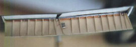
The part of the wing housing the flaps was duly modified. The large flap in fact consists of two portions which overlap and accommodate the different angles of the wing inner and outer sections. The upper wing exposed part was lined with thin plastic card. These do not meet but there is a gap in between coinciding with the change in the wing angle. The front edge of this space is rounded and this was produced by cutting a section of aluminium tubing length wise, fixing in place and sanding off till flush with the top and bottom wing halves. The sides were also closed off with plastic card and holes prepared to accommodate the flaps' shaft. Care was taken to sand down the wing trailing edge to a fine thickness.
Flaps were scratch built from thin gauge plastic card. Thicker card was used to make the ribbing. These were individually produced but pre drilled to take the shaft running through the whole flap. The latter was made from copper rod. The socket connecting the shafts for both flaps and the bearings for the flaps were made from aluminium tubing which fitted snugly on the outside of the copper rod. The rib spacing was taken off scale plans and checked against a head on photograph showing the lowered flap.
Wheel Wells
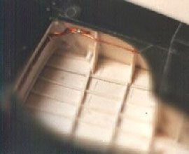
The next area to be detailed was the wheel wells. I must admit that this was the most difficult because of a total lack of information and photographs. I shall also say that some of the details from the Tempest wheel wells were copied into the model. However, for lack of a better alternative, this had to do. For some reason which I do not remember, I had covered the inner upper wing half with thin plastic card to have a smooth bottom in the wells. Most probably, the kit plastic was very rough in this area and there might have been some crude detail which I would have removed, leaving an uneven face. The areas were completely scratch built from plastic card, plastic rod and strip. A compressed air cylinder was made from scrap sprue plastic. Retaining clips for the cylinder, wiring and pipes was made from surgical blade covers. Apart from the basic shape of the wheel well including sections of ribs, other details included various pipes and wires and the locking mechanism for the undercarriage assembly.
Gun Bay
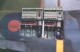
The gun bay construction consisted of two distinct parts, the gun bay itself and the gun bay doors. The bay area was first cut open. The plastic was carefully cut out and reused. Plastic strip was added to the edges to make up for the material lost when cutting. These doors are made up of two distinct parts which fold out onto the front of the wing. The plastic removed from the wings was thinned down to obtain a knife edge thickness. Details on the gun bay doors was made from a mixture of plastic card, plastic rod and strip, fuse wire and copper wire. The area housing the ammo feed drums was hollowed out. The hinge between the two parts was made from plastic rod and copper wire. The fasteners were made from plastic rod. When located in place, these doors rest on the wing leading edge and also on the gun barrels.
A completely new gun bay was built up from plastic card, strip and wire. The wing surface was used for the bay floor. This was sanded smooth and all imperfections removed. The Hispanos and ammo feed drums were scratch built from plastic. A central partition which in actual fact was one of the wing spars was constructed from plastic card and flat strip. Circular and oval openings in the sides and partition were done using drills. The innermost bay includes the actuating piston for the flaps. This was made from copper tube and plastic rod inserted into it. Gun cocking mechanisms, pipes and wiring were made from copper and fuse wire. The gun bay sides were left slightly smaller than the opening so as to have a small but significant edge on which to rest the gun bay doors. The ammo boxes were made from thin sheet aluminium and the 20mm shells from copper wire. Strips of wire were held in a mini drill chuck and honed over sand paper until the required shell front was formed. These pointed ends were then cut to size. Surgical blade covers were used to make the ammo belt and hold the shells together.
At this point in construction, a great sigh of relief was the installation of the wings' assembly to the already completed fuselage. At this stage, the model really starts to take on a new dimension. The remaining amount of detailing included minor items when compared to what was already achieved.
Wheel Doors and Undercarriage
The kit's larger wheel doors were accurate in shape. The inner doors, however were smaller. These were detailed and thickened using plastic card and copper rod. The inner wheel cover actuators and hinges were made from metal tubing and wire. Certain areas on the smaller doors were hollowed out to form indentations. The larger doors were made up from three distinct sections, the very thin overall plate and two thicker areas with space for the wheel leg.
The tyres were built up with Milliput and sanded to shape to give a weighted look. All undercarriage legs and actuating mechanisms are scratch built using copper and aluminium tubing. Besides detailing these parts, metal was used to give strength and stability. Although the Typhoon undercarriage is pretty complicated, it should be studied carefully and constructed bit by bit. This is very well illustrated in the publication titled 'Typhoon Portfolio'. The individual assemblies were then pinned together for strength and also to allow for a final setting.
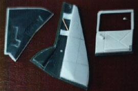
The Famous Car Door
The door supplied with the kit was used as an outer skin. Kindly note that the Typhoon cockpit door was really a car door. The door thickness was built up using plastic card and strip. A slot was left for the glass to slide through since this could be wound up or down. Do not forget to include the winding handle for the window, it could get hot in there!! A piece of clear acetate was used to substitute for the window. This was left half open.
Canopy
The kit canopy was used as the male mould. The front portion was separated from the rest and treated as a separate part. This made the making and installation of the canopy easier. These two sections were filled with Milliput so as not to cave in when put in contact with the hot acetate. Each part was then mounted on a brass rod which set into the Milliput. This would allow these to be held tightly in a vice until the hot clear acetate is stretched over them. Finally, the canopy framing was slightly lowered using 1200 gauge wet or dry sandpaper and the entire canopy polished using a rubbing compound. All clear canopy parts were then moulded.
The worst experience when constructing the canopy is the formation of a slot in the rear portion through which passed the radio aerial. This was cut out carefully with a knife and then filed to shape. When the main canopy was produced, the top part was separated so as to be fixed in the open position. Framing complete with handles was then added on to the clear part.
Other Miscellaneous Details
The rear part of the canopy which is pear shaped includes an array of aerials and lights. These were all painstakingly reproduced off photographs. The most obvious of these details are a clear hemispherical bulb behind the radio antenna, the red light just behind the antenna on the outer face of the canopy and connecting wiring.
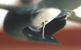
The foot rest beneath the cockpit was made from odds and ends including brass rod, extra brass from photo etched frets and plastic. A corresponding slot in the fuselage should not be forgotten since this would have been retracted when not in use.
Painting
Areas such as the cockpit interior, engine and wheel wells were painted during construction. After painting in the appropriate colours, a thinned oil paint (burnt umber) wash is applied. The oils are thinned down using white spirit. After a couple of days, when the oil paint is properly dried, all parts are dry brushed with the appropriate lighter shades. This greatly enhances all details. The cockpit interior, wheel wells, engine cover and gun bay was painted in interior green. Washes and dry brushing completes the job as usual and adds life to your work. This is the stage when your modelling really shows up and all those bits and pieces of plastic, copper, brass aluminium and any other material you choose to work with take on a new dimension and look REAL!!!
Now for the model itself. All painted areas such as the cockpit, engine, wheel wells and gun bay were carefully masked. In the case of the engine, this was covered with PTFE tape. This adheres to detail without sticking on and I like to use it for masking delicate areas such as engines and wheel legs. The engine cover was then fixed in the closed position with a spot of Crystal Clear. This ensured a continuation of the camouflage pattern during painting.
As for the painting procedure, one may refer to my previous article where I describe the painting of my Me 262s. The sequence is standard and the materials used are also the same. The camouflage colours were mixed specifically for the job using Humbrol enamels, the IPMS colour guide and a fan deck of FS colour chips.
The sequence followed to paint the model was as follows:
- Underside Grey.
- Topside Grey.
- Topside Green.
- Thick white band covering invasion stripes area.
- Black bands over white.
- Sky band around rear fuselage.
- Yellow for leading edge and wing stripes.
- Other parts such as flaps and wheel doors.
The only experiment I made when painting the Typhoon was the following which was highly successful and really paid off. In order to avoid disappointment when correcting mistakes, the model was given a number (usually 4 to 5) of thinned down gloss varnish coats following the completion of any particular colour. Thus, when applying the next colour, any mistake may be rectified with gentle sanding. This will result in the removal of the unwanted paint and maybe some of the varnish. However, the colour underneath is left untouched. This procedure was carried out after each step mentioned above. As for the stripes, varnish was locally applied in that particular area to avoid unnecessary build up of varnish over the whole model.
A complete lack of accurately coloured decals prompted me to actually paint the national markings onto the aircraft. This resulted in a really nice effect since, like all the other colours, these were also weathered. Decals were only used for the serial number, code letters and Squadron Leader's pennant. PR were cut out from the kit's decal sheet and sprayed sky. The G was unavailable and was made from clear decal and sprayed. The 609 Squadron crest, motto and kill markings were hand painted by brush on clear decal.
When all decals were in place, thinned gloss varnish was sprayed over them and their immediate surrounds. This is left to dry and sanded down smoothly. The process is repeated as necessary until the decal edge is eliminated and merged into the model finish. When this process in completed, the decal outline should be invisible when viewed against the light. As an aside, this technique may be used to make good any defects which could have gone unnoticed up to this stage such as minute scratches, sink marks and the elusive joint line which no filler could make right. A little cheating is allowed as long as its for a good cause!!
The roundels were sprayed directly onto the kit. A thin clear sheet of acetate and a compass cutter were used to produce them. The method used was to start with the largest size circle and work inwards to the smallest. Take the wing topside roundels for example. The blue circle is measured and cut out of the acetate. This is taped onto the kit and sprayed using the usual three shade technique. This same diameter is then marked on another piece of acetate but not cut. Using the same centre for the compass, the red circle is cut out. This way, you are left with a piece of acetate with the blue outline marked out and the red circle missing.
This template may then be aligned with the blue circle and taped again to the model. The red circle may then be sprayed on. This method ensures that the circles are concentric. Any other attempts to obtain concentric circles failed miserably and resulte in much sanding and respraying. Then, when I was about to despair and give up, my wife who heard curses which cannot here be reproduced came up with this simple but ingenious brain wave. Unlimited thanks to her for saving me in that hour of great darkness. As mentioned above, I used gloss varnish to separate the blue from the red colours. This procedure was repeated for all the other roundels.
The final gloss varnish coats are left to dry for at least 48 hours. All panel lines were then given a wash with oil paint (burnt umber) thinned with white spirit. The paint should be thinned enough to allow easy flow of the paint along the panel lines. At this point, there will be over spilling of the paint from the panel lines but his will be dealt with later. The wash is left to dry for at least four days. The whole model is sanded down again using the wet and dry 1200 grade paper. This process should be carefully and lightly carried out with used sandpaper. This will allow for gradual removal of surface defects and the excess wash. The result should be a very smooth, blemish free surface.
Details such as aerials, pitot tube and undercarriage are all fixed in place. I like to fix these parts at such a late stage to avoid countless handling accidents since the model is sanded down at least three times in the process described above. One cannot sand the whole model down satisfactorily if certain items are in place.
My favourite stage follows. Weathering in the form of paint wear, gun and exhaust stains are put on the model. This procedure is also well explained in my previous article for the Me 262's. When this is complete and all defects have been remedied, a couple of coats of thinned matte varnish are sprayed over the whole kit for a good even finish. Once again, I prefer the Revell matte varnish since this is absolutely clear and does not yellow.
Before installing the canopy, the scratch built gun sight was located in place. The final stage consisted of the installation of the canopies. These were trimmed to shape. It is good to mould a few extra parts since there is always the inevitable scratch or imperfection or one might trim a bit too much. Clear decal sheet is sprayed with interior green and the camouflage colours. Thin strips of decal are then used to frame the canopy, green on the inside and the camouflage on the outside. The rear portion of the canopy, however was sprayed both inside and out since its complicated shape did not allow for decal to be used. The canopy was then fixed in place using Crystal Clear. The top middle part of the canopy was fixed in the open position. The last item to be fixed onto the model, of course was the Car Door. The Typhoon would not be complete without the car door which was fixed in the open position.
References
Following is a list of references which were used to build the model. Some of this literature pertains to the Tempest. Liberal use of this material was made due to lack of details regarding the Typhoon.
Books
- Typhoon and Tempest at War. - Reed and Beamont
- Typhoon/Tempest in Action - Squadron Signal
- Hawker Typhoon Portfolio - Brooklands Books
- The Hawker Typhoon - Profile Publications
- Hawker - An Aircraft Album - Arco
- Fighters of World War Two Vol. 2. - Argus Books
- The Hawker Tempest - Modelpress
- Famous Fighters of the Second World War Vol. 1. - William Green
Magazine Articles
- Tropical Typhoon by Jordan Ross - Scale Modeller
- Hawker Typhoon by Arthur Bentley - Scale Models
- Focus on a 1/32 Hawker Typhoon by Ray Rimmel and Bob Jones - Scale Models
- The Typhoon by Richard Caruana - Air Forces International
- Hawker Typhoon by Alan W. Hall
- Tempest Summer by Roland Beamont - Aeroplane Monthly
© Brian Cauchi
This article was published on Wednesday, July 20 2011; Last modified on Saturday, May 14 2016