
Combat Models 1/32 Ju 52
By Forrest Cox
Combat Models 1/32 Tante Ju
I built this vacuform kit several years ago and took it to one contest. I put my soul into the construction of the kit and being a contest rookie made some minor mistakes that put it at the bottom of the judges list. I guess we all have done that. I have wanted to share my experience building it but up to now have not had the time.
It started life as a Combat Models vacuform. I didn't know about the Schmitt Modelbau kit until after this one was completed. I was able to purchase the Schmitt kit later and compare the two. The Schmitt kit had many more white metal parts, thicker plastic and better detail. The Schmitt kit is a much nicer start than the Combat kit; however, both will take a lot of work. I believe good results can be achieved from both.
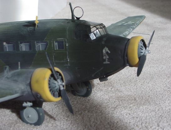
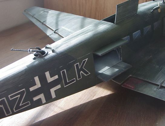
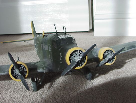
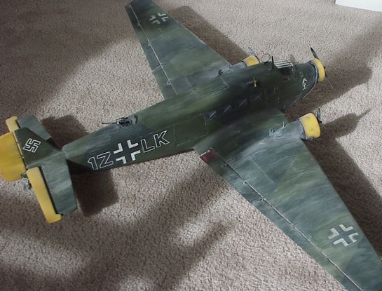
The Tante Ju I chose to model was 1Z+LK, many photographs survived the war to be later published and this reference proved very valuable in replicating this example. I even found a photograph of it in its final resting place near El Alamein in North Africa. The effort required close to 200 hours to complete from start to final finish. It has a 36" wings span and measures just under 22.5" long from prop to tail.
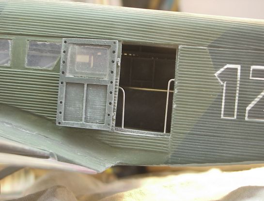
The most wonderful part of building the Tante Ju in this scale is that there are as many interesting things to model in the inside as the outside. The panels of corrugated Duralumin also made up the bulkhead coverings, cockpit doors, bathroom door and wall panels inside. Yes many of the Ju 52s had a toilet in the rear. It seems Germany was one of few countries using the western toilet during that period of time.
Research references were very hard to find at the time, I was able to come up with some gems. A list is included as an addendum.
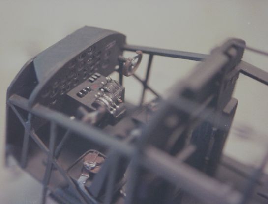
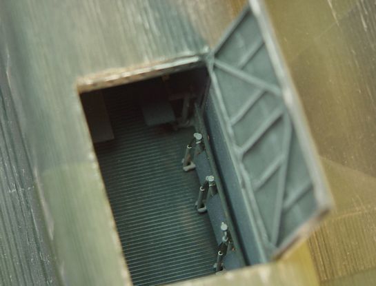
I wanted to model the interior in detail and started with a skeletal buildup of bulkheads, struts, longerons and floor. I fit each bulkhead to the fuselage half as I worked my way aft one bulkhead at a time. I constructed the cockpit, bathroom, radio station and rear gunner station inside this skeleton. All the doors in this model are operational, some you see in the photos, others like the cockpit and bathroom doors are not quite as visible but are also operational. Hinges are styrene sheet drilled and pinned with .020 brass rod.
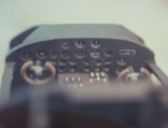
I used Waldron instruments and seat belt hardware. The remainder of the cockpit and interior was built from scratch using styrene card. The guys at the Whistle Stop where I got most the styrene were sure curious as to what I was building with all that styrene. I never did tell them, it was more fun not to.
The benches in the rear of the real planes fold up for moving cargo or fold down for transport of troops or wounded. The benches in this kit also can be raised or lowered as I copied the design from the original aircraft. I did this by soldering small brass tube into a supporting frame. Drilling holes in each vertical bar at the hinge line and inserting small brass rod as a hinge. The support for the benches is hinged to the vertical bar where it meets the floor and has a collapsing brass rod inside that extends out when the seat is raised and collapses inside when the bench is lowered. The benches were painted and installed before adding the tail section to the skeleton.
I painted the skeleton Gray using Model Master Enamels and dry brushed highlights with a lighter shade of gray. I weathered wear patterns with dull aluminum and set the skeleton aside to work on the fuselage halves.
Doors were molded very close to actual locations and were cut out and set aside. I make a window pattern out of 1/16th aluminum. I used a scribe to mark the upper and lower window ledges all at once. This insured they would be parallel. I then measured the width of each window and space between them along the bottom line and make vertical scribes at 90 degrees to locate each window. I then carefully removed the aluminum from inside the pattern with drill, Dremmel tool and files.
Using my new pattern I marked and cut out the windows along the left side of the fuselage. I used the same pattern to cut the windows out of clear sheet supplied with the kit. I was all set to just turn this over for the other side when I discovered minor differences in the location and spread of the right side windows. I was forced to go through the process again for the right side.
The results were worth it. The windows all lined up and looked correct according to the drawings and photos. Next I completed the door frames, pillars, hinges and interior door structures on the inside of each door. The visible interior was now close to completion and time to move on to the wings.
I built the wings as separate units using ¼" styrene sheet as wing spars with wing struts spaced every two inches along the span. I left the spars extending about an inch out the end of each wing. I used the ¼" sheet to form the landing gear mounts and drilled holes for the white metal landing gear struts through the lower wing covering. Another requirement was to clean up the corrugation. I used a small round file to remove imperfections by running it down each line to remove small islands of styrene left by the forming process. This was very time consuming but worth the effort, as it unified the corrugation pattern.
It was now time to engineer the wing roots and supporting structure of attaching the wings. I chose to build a supporting structure inside the fuselage and attach each wing separately. WRONG!!!! By the time I found this out I was trapped and could not revert with out destroying a big part of what had already been completed.
We all know about modeling pain, right? The sinking feeling you get when you realize you just instant glued your bran new T shirt to the tweezers. While I would never freely admit to doing this, I do understand the meaning of modeling pain and that it is almost always self-inflicted.
If you decide to build one of these or any other large vacuform aircraft, I recommend you separate the wings and fuselage at the wing roots. Build the wings as a separate single structure then attach them to the fuselage. This may seem like common sense to most of you but I'm not that smart. By doing it this way you will avoid problems with wing dihedral, incidence angles and alignment positions not matching from side to side. It is much easier to match all this on a connected set of wings then attach them to the fuselage as a unit. Adjustments to these angles then affect both wings equally and will minimize your modeling pain considerably and allow you to resist the compelling urge to smash the whole project into a million pieces and stuff it into the closest dumpster.
Matching the wings to the fuselage with this connection design was a nightmare. I probably spent 20 plus hours with fit and alignment of the wings to fuselage. It really doesn't have to be that painful. I didn't know any better and having now tried both methods can confirm the ease of the later method. You; however, no longer have an excuse for inflicting this much modeling pain on yourself.
With the basic wings and connecting structure completed I turned back to completion of the fuselage. I cleaned up the corrugation, added the windows using diluted white glue to attach them inside the matching openings. I cut the hole for the gunner station and cockpit. I created the geared base for the rotating rear gun mount. I painted the inside to match the skeleton and glued it into place. Following the same procedure for the right side I added the ventral gun base then glued the halves together.
My attentions now focus on detailing the outside, Fuel and Oil gauges were added to the top rear of the engine nacelles. Three Engines and Things engines were modified to closely resemble the BMW engines. I added the white metal exhaust stacks included in the kit to the center engine and added scratch built ones to the outer engines. The birdcage canopy was glued into place with small dots of instant glue in the corners and diluted white glue to finish the seams.
The outer engine shrouds were also a challenge both to build and to install. They are round on the front around the engine and oval on the back to match the nacelle on the wing. This is an odd combination to try and form from shroud halves provided in the kit. As soon as you try and squeeze the nacelle into an oval in the rear it will crack along the joint.
Modeling pain can be experienced here also. I tried several different methods and ended up cutting a half oval pattern out of wood to match the oval I needed. I then formed the plastic with a hot hair dryer pulled over the pattern. The halves of the nacelle then matched close enough to allow final forming without cracking.
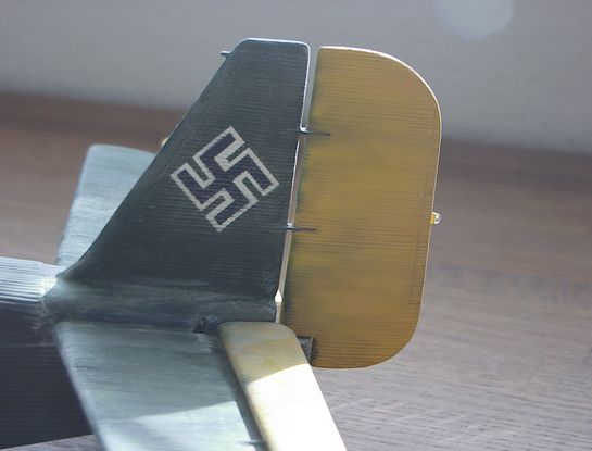
The vertical and horizontal stabilizers were matched and the corrugation cleaned as above. I also did the elevators, rudder, ailerons and flaps. These all matched up pretty good and these simple tasks allow for a reasonable amount of patience to return. I attached the stabilizers and added attachment points for the movable surfaces. This was a great idea but the parts are so large they drooped so I glued them into place.
I utilized the kits wheels, scratch built a pitot tube, generator and generator propeller and dropped the wheel spats into the spares box. I also added navigation lights, radio masts and scratch built the remainder of the ventral gun position. I now added the white metal landing gear struts and tail wheel. These went on easily as they were pre fit during the construction of the wings and fuselage skeleton.
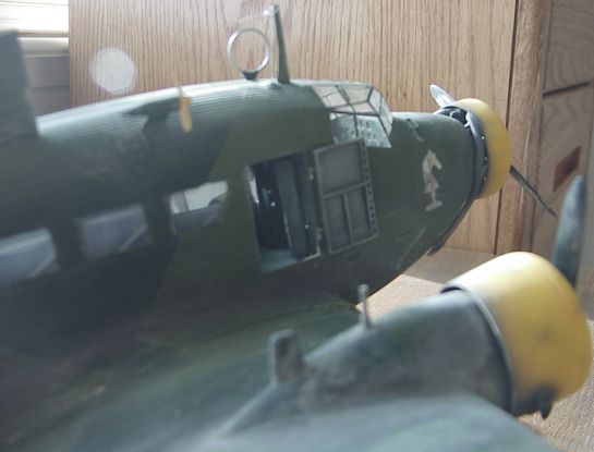
The kit was now ready for paint. The Dark Green, Light Green color scheme with gray undersides was prevalent in all photos of this aircraft. The underside was sprayed first after careful masking of the engines and canopy. I painted the standard upper camouflage pattern with yellow engine nacelles, elevators and rudder to mark the Mediterranean Theatre of operations.
The Tante Ju is heavily weathered, although I can only take partial credit for that. Dave Runkle of Rhino Models spent quite a bit of time showing me how to do weathering on this kit. Things I didn't think of like dry brushing base colors over the trim colors to simulate faded or work colors. The concept of weathering fuselage windows was also a surprise to me. He made his point by asking who I thought took the time to clean the windows. To me the weathering is what makes this presentation. It really looks as well worn as any Tante Ju would have.
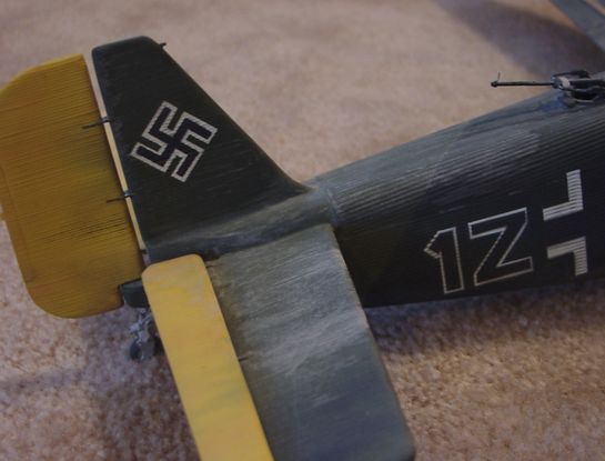
The insignia are all painted. There are no decals anywhere on the kit. Dave came to my rescue again to show me how easy it is to use an air brush and stencil to add markings. The key is a sharp knife, and careful placement. Spray the paint thin, but from a distance of about 6 inches. It kind of fogs on the paint, it covers well with a thin coat and did wonders to make the finish look authentic. I added exhaust, oil and fuel stains to the main finish then added several heavy dusty colored washes. The kit was then sealed with a matt clear to seal all the paint and weathering.
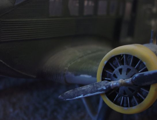
Final details were added. The white metal props were painted black, weathered and installed. The rear gunner station was completed. The canopy masking removed and several other small parts touched up with paint. I installed doors and wheels.
Well there you have it. This is my rendition of 200 hours of modeling fun, with some modeling pain and a whole lot of satisfaction. I recommend that everyone should try a large vacuform at least once. It will put your modeling and engineering skills to the test. I tried to copy the basic engineering design of the original aircraft. It helped to be able to get ideas for how to construct supporting structures from pictures and drawings of the aircraft. This can go too far, the wings are the prime example of this.
Have fun that's what it's all about.
References
Combat Models 1/32 Tante Ju
I built this vacuform kit several years ago and took it to one contest. I put my soul into the construction of the kit and being a contest rookie made some minor mistakes that put it at the bottom of the judges list. I guess we all have done that. I have wanted to share my experience building it but up to now have not had the time.
It started life as a Combat Models vacuform. I didn't know about the Schmitt Modelbau kit until after this one was completed. I was able to purchase the Schmitt kit later and compare the two. The Schmitt kit had many more white metal parts, thicker plastic and better detail. The Schmitt kit is a much nicer start than the Combat kit; however, both will take a lot of work. I believe good results can be achieved from both.
The Tante Ju I chose to model was 1Z+LK, many photographs survived the war to be later published and this reference proved very valuable in replicating this example. I even found a photograph of it in its final resting place near El Alamein in North Africa. The effort required close to 200 hours to complete from start to final finish. It has a 36" wings span and measures just under 22.5" long from prop to tail.
The most wonderful part of building the Tante Ju in this scale is that there are as many interesting things to model in the inside as the outside. The panels of corrugated Duralumin also made up the bulkhead coverings, cockpit doors, bathroom door and wall panels inside. Yes many of the Ju 52s had a toilet in the rear. It seems Germany was one of few countries using the western toilet during that period of time.
Research references were very hard to find at the time, I was able to come up with some gems. A list is included as an addendum.
I wanted to model the interior in detail and started with a skeletal buildup of bulkheads, struts, longerons and floor. I fit each bulkhead to the fuselage half as I worked my way aft one bulkhead at a time. I constructed the cockpit, bathroom, radio station and rear gunner station inside this skeleton. All the doors in this model are operational, some you see in the photos, others like the cockpit and bathroom doors are not quite as visible but are also operational. Hinges are styrene sheet drilled and pinned with .020 brass rod.
I used Waldron instruments and seat belt hardware. The remainder of the cockpit and interior was built from scratch using styrene card. The guys at the Whistle Stop where I got most the styrene were sure curious as to what I was building with all that styrene. I never did tell them, it was more fun not to.
The benches in the rear of the real planes fold up for moving cargo or fold down for transport of troops or wounded. The benches in this kit also can be raised or lowered as I copied the design from the original aircraft. I did this by soldering small brass tube into a supporting frame. Drilling holes in each vertical bar at the hinge line and inserting small brass rod as a hinge. The support for the benches is hinged to the vertical bar where it meets the floor and has a collapsing brass rod inside that extends out when the seat is raised and collapses inside when the bench is lowered. The benches were painted and installed before adding the tail section to the skeleton.
I painted the skeleton Gray using Model Master Enamels and dry brushed highlights with a lighter shade of gray. I weathered wear patterns with dull aluminum and set the skeleton aside to work on the fuselage halves.
Doors were molded very close to actual locations and were cut out and set aside. I make a window pattern out of 1/16th aluminum. I used a scribe to mark the upper and lower window ledges all at once. This insured they would be parallel. I then measured the width of each window and space between them along the bottom line and make vertical scribes at 90 degrees to locate each window. I then carefully removed the aluminum from inside the pattern with drill, Dremmel tool and files.
Using my new pattern I marked and cut out the windows along the left side of the fuselage. I used the same pattern to cut the windows out of clear sheet supplied with the kit. I was all set to just turn this over for the other side when I discovered minor differences in the location and spread of the right side windows. I was forced to go through the process again for the right side.
The results were worth it. The windows all lined up and looked correct according to the drawings and photos. Next I completed the door frames, pillars, hinges and interior door structures on the inside of each door. The visible interior was now close to completion and time to move on to the wings.
I built the wings as separate units using ¼" styrene sheet as wing spars with wing struts spaced every two inches along the span. I left the spars extending about an inch out the end of each wing. I used the ¼" sheet to form the landing gear mounts and drilled holes for the white metal landing gear struts through the lower wing covering. Another requirement was to clean up the corrugation. I used a small round file to remove imperfections by running it down each line to remove small islands of styrene left by the forming process. This was very time consuming but worth the effort, as it unified the corrugation pattern.
It was now time to engineer the wing roots and supporting structure of attaching the wings. I chose to build a supporting structure inside the fuselage and attach each wing separately. WRONG!!!! By the time I found this out I was trapped and could not revert with out destroying a big part of what had already been completed.
We all know about modeling pain, right? The sinking feeling you get when you realize you just instant glued your bran new T shirt to the tweezers. While I would never freely admit to doing this, I do understand the meaning of modeling pain and that it is almost always self-inflicted.
If you decide to build one of these or any other large vacuform aircraft, I recommend you separate the wings and fuselage at the wing roots. Build the wings as a separate single structure then attach them to the fuselage. This may seem like common sense to most of you but I'm not that smart. By doing it this way you will avoid problems with wing dihedral, incidence angles and alignment positions not matching from side to side. It is much easier to match all this on a connected set of wings then attach them to the fuselage as a unit. Adjustments to these angles then affect both wings equally and will minimize your modeling pain considerably and allow you to resist the compelling urge to smash the whole project into a million pieces and stuff it into the closest dumpster.
Matching the wings to the fuselage with this connection design was a nightmare. I probably spent 20 plus hours with fit and alignment of the wings to fuselage. It really doesn't have to be that painful. I didn't know any better and having now tried both methods can confirm the ease of the later method. You; however, no longer have an excuse for inflicting this much modeling pain on yourself.
With the basic wings and connecting structure completed I turned back to completion of the fuselage. I cleaned up the corrugation, added the windows using diluted white glue to attach them inside the matching openings. I cut the hole for the gunner station and cockpit. I created the geared base for the rotating rear gun mount. I painted the inside to match the skeleton and glued it into place. Following the same procedure for the right side I added the ventral gun base then glued the halves together.
My attentions now focus on detailing the outside, Fuel and Oil gauges were added to the top rear of the engine nacelles. Three Engines and Things engines were modified to closely resemble the BMW engines. I added the white metal exhaust stacks included in the kit to the center engine and added scratch built ones to the outer engines. The birdcage canopy was glued into place with small dots of instant glue in the corners and diluted white glue to finish the seams.
The outer engine shrouds were also a challenge both to build and to install. They are round on the front around the engine and oval on the back to match the nacelle on the wing. This is an odd combination to try and form from shroud halves provided in the kit. As soon as you try and squeeze the nacelle into an oval in the rear it will crack along the joint.
Modeling pain can be experienced here also. I tried several different methods and ended up cutting a half oval pattern out of wood to match the oval I needed. I then formed the plastic with a hot hair dryer pulled over the pattern. The halves of the nacelle then matched close enough to allow final forming without cracking.
The vertical and horizontal stabilizers were matched and the corrugation cleaned as above. I also did the elevators, rudder, ailerons and flaps. These all matched up pretty good and these simple tasks allow for a reasonable amount of patience to return. I attached the stabilizers and added attachment points for the movable surfaces. This was a great idea but the parts are so large they drooped so I glued them into place.
I utilized the kits wheels, scratch built a pitot tube, generator and generator propeller and dropped the wheel spats into the spares box. I also added navigation lights, radio masts and scratch built the remainder of the ventral gun position. I now added the white metal landing gear struts and tail wheel. These went on easily as they were pre fit during the construction of the wings and fuselage skeleton.
The kit was now ready for paint. The Dark Green, Light Green color scheme with gray undersides was prevalent in all photos of this aircraft. The underside was sprayed first after careful masking of the engines and canopy. I painted the standard upper camouflage pattern with yellow engine nacelles, elevators and rudder to mark the Mediterranean Theatre of operations.
The Tante Ju is heavily weathered, although I can only take partial credit for that. Dave Runkle of Rhino Models spent quite a bit of time showing me how to do weathering on this kit. Things I didn't think of like dry brushing base colors over the trim colors to simulate faded or work colors. The concept of weathering fuselage windows was also a surprise to me. He made his point by asking who I thought took the time to clean the windows. To me the weathering is what makes this presentation. It really looks as well worn as any Tante Ju would have.
The insignia are all painted. There are no decals anywhere on the kit. Dave came to my rescue again to show me how easy it is to use an air brush and stencil to add markings. The key is a sharp knife, and careful placement. Spray the paint thin, but from a distance of about 6 inches. It kind of fogs on the paint, it covers well with a thin coat and did wonders to make the finish look authentic. I added exhaust, oil and fuel stains to the main finish then added several heavy dusty colored washes. The kit was then sealed with a matt clear to seal all the paint and weathering.
Final details were added. The white metal props were painted black, weathered and installed. The rear gunner station was completed. The canopy masking removed and several other small parts touched up with paint. I installed doors and wheels.
Well there you have it. This is my rendition of 200 hours of modeling fun, with some modeling pain and a whole lot of satisfaction. I recommend that everyone should try a large vacuform at least once. It will put your modeling and engineering skills to the test. I tried to copy the basic engineering design of the original aircraft. It helped to be able to get ideas for how to construct supporting structures from pictures and drawings of the aircraft. This can go too far, the wings are the prime example of this.
Have fun that's what it's all about.
References
- Junkers Ju52, Heinz J. Nowarra
- Die Ju52 im Zweiten Weltkrieg, J. Piekalkiewicz
- Luftfahrt Bilder, Texte Dokumente, Volume 23, Mittler
- Foto-Archiv, Band 3, Flugzeug
The Saga of Iron Anne, Martin Caidin - German Aircraft Landing Gear, Gunther Sengfelder
- Das Buch Der Deutschen Luftfahrttechnik, Verlag Dieter Hoffmann
- West of Alamein, Colonel G.B. Jarrett
- Movie 'Where Eagles Dare' MGM 1968
© Forrest Cox 2003
This article was published on Wednesday, July 20 2011; Last modified on Saturday, May 14 2016