
Scratchbuilders Revised 1/32 Me 410
By Frank Mitchell
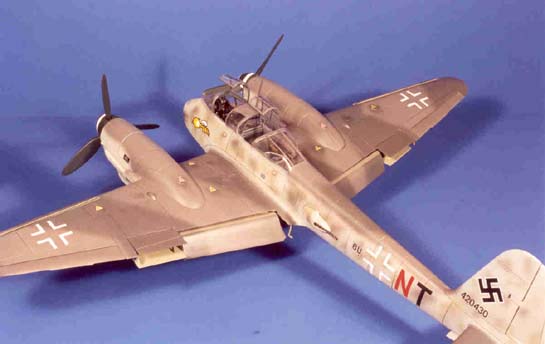
The Me 410 has been kitted three times (that I know of) in 32nd scale: a Combat vacuform kit in the late '60s and the first Scratchbuilder's kit several years ago. Unfortunately, both had a number of inaccuracies. The newly available Revised Scratchbuilder's kit has been much improved in both accuracy and ease of building. As is normal with many cottage industry kits, they do not fall together, but with some work and patience, the result can be a very nice model of this intriguing aircraft. The goal of these notes is to provide some hints on building the 410 and hopefully encourage others to give it a try.
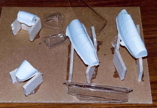
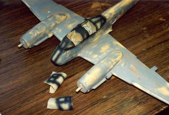
An Me 410 is all about the forward fuselage. The canopy, in particular, with its bulged sides and heavy turn-under, is a tough nut to crack and was one of the main reasons I never got very far on either of the previous kits. The new kit, however, has a three (actually four) piece canopy that has the windscreen and pilot's canopy as separate pieces while the main canopy is in two parts, split longitudinally along the top. The intention is to match up the two halves along a frame line.
Although the kit's canopies are well formed, I don't like molded-in frames in vacuum-formed canopies. I think that they look very over-scale and clumsy. Besides, I had a hunch that one set of canopies would not be enough, given errors in trimming, etc. I therefore made new molds from the kit canopies using plaster which was covered with epoxy and formed new ones from vinyl. It took three sets of canopies, slowly trimming the parts as I went, before I managed to get a set that a) looked right, b) fit correctly onto the taped-together fuselage, and c) also had the seam lined up with a frame. The latter was important not only because I wanted to hide the seam but also because I wanted to open the rear cockpit and that meant that the seam had to be in the right line. The opening portions were molded separately. Small strips of styrene were glued along the hinge line of both the fixed and opening parts and very small pieces of brass wire were glued into the open portion to hold the open canopies in place.
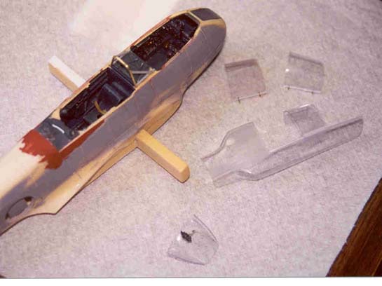
Detailing the interior is very straightforward thanks to the way the fuselage is broken down. It is really just a matter of digging out the references and diving in. You do need to decide what variant you want to build, since the gunsight varies with the version (I substituted Insight parts for the ones supplied.) Although the kit gives some cockpit parts in resin and white metal, there are still a fair number of pieces to make. I also re-made a few because they looked a bit over scale to me. Things are also a bit more complicated than usual because the instrument panels have to be mounted on the sides of the fuselage. Because the backs of the panels are visible, instrument cases and wiring have to be added. On the positive side, having the bottom of the cockpit area as a separate piece made access a lot easier. I also made new clear panels for the extreme nose because I knew that they would be getting a fair amount of sanding and I thought that life would be easier if those parts were Plexiglas.
A new roll-over structure between the crew seats was made up from brass wire and plastic rod. The very prominent round tubing outlining the canopy openings was made from flexible solder and glued inside the canopy. The canopy was not glued into place until much late in construction.
The round barbette gun fairing bases were sanded to match the openings in the fuselage, and small plastic spacers added to make sure that the barbettes would be flush with the fuselage sides. In my kit, both of the gun fairing openings were flashed over, but that worked in my favor since the openings were really too large. They are supposed to hug the gun pretty closely. Therefore, I filled the depression on top of the flashing with epoxy, sanded it smooth and cut new openings. The guns themselves were nice castings and I only modified them as necessary to fit properly into the fairings.
The fuselage sections fit pretty well, just needing some sanding to fit properly. They were joined using CA, but before filling the seams with epoxy, four holes were drilled through the junction of the forward and center fuselage sections. Brass wire pins were CA'd in place and smoothed off. I did not want that joint to fail.
The vertical fin and rudder needed only minor sanding to fit the fuselage well. Holes are even supplied to insert some aluminum tubing to sturdy things up. An actuating rod for the trim tab was added to the rudder. The horizontal stabilizers are shaped well, but were to my eye somewhat too thick. A short session on the belt sander took care of that. The elevators were pinned to the stabilizers at a slight down angle. They were not glued in place at this time, nor were the stabilizers.
There was some warpage in one wing, but a little hot water and bending took care of that. The top portions of the wings (2 per side) were fitted in terms of length and width. A fair amount of sanding was done along the top rear of the main wing pieces and the bottom rear of the top pieces to obtain a much sharper trailing edge. That accomplished, the wing tops were glued to the wings with epoxy and superglue. As is fairly normal for these kits, the tops of the wings were a bit wavy. That is probably a trade-off for the method of molding, which does result in a very stiff wing. That is important in a heavy resin model. A layer of filled epoxy was applied to the low spots in the top surfaces, and the whole thing was block-sanded until the wing surfaces were smooth and straight.
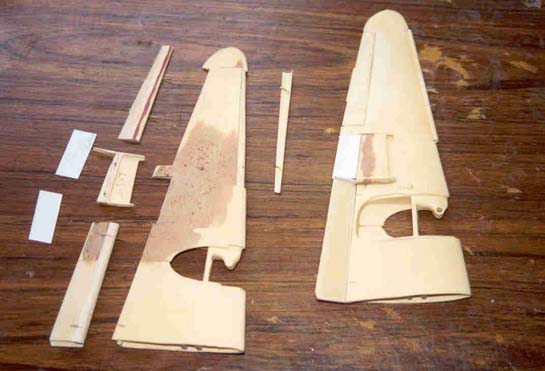
Although the substantial mounting for the wings works very well, there was still some rotational movement of the wing which would make getting the landing gear, engine nacelles and props lined up properly a bit difficult. Therefore, holes were drilled into the rear section of the wings for two pieces of tubing which fit into matching holes in the wing root, making the wing very stable. One of the under-wing radiators was a bit longer than the other, and both were too short by about an 1/8". Each was sliced through the center section and spacers of 1/8" balsa were superglued in place and sanded smooth. Each radiator was then fitted and pinned to its respective wing surface, and the movable sections were removed and replaced by styrene pieces pinned with brass wire for easy assembly after painting.
The flaps were sawn off, and balsa was added to shape their nose. Brass pins were then placed to position the flaps in a lowered position. The ailerons required some thickening so that they would match the wing. 1/16" balsa was superglued to the top surface of each and the ailerons were sanded to match their opening. The leading edge slats were supplied in the kit and only some sanding and squaring off of the ends and the slat "wells" in the wing were necessary. One opening was slightly too long, so a piece of scrap plastic was fitted and superglued in place, then sanded to shape. The slats were also pinned for later assembly.
The ventral gun housing was sanded to fit, and brass-wire pins put in place to mount it correctly. It was not permanently attached until painting was complete. The large landing gear doors were fitted to their respective openings. Thankfully, they are closed on the ground, so no detailing is necessary. They fit pretty well, so only minor sanding was necessary.
The engine nacelles fit reasonably well, just needing some sanding and clean-up. Plastic strip was superglued inside the nacelle moldings behind the exhaust openings to serve as mounts for the white metal exhaust stacks. The distinctive shrouds that cover the exhausts are supplied in the kit and needed only to be sanded to fit the slots provided for them. The shrouds mean that not much has to be done to the exhausts themselves but cleaning up their somewhat pitted surfaces. One of my engine nacelles was a bit indented along the left side, so a scrap piece of 1/2" balsa was cut to size and wedged and glued into the engine. That served to push the nacelle side back out to where it should be.
A modification was made to the way the kit suggests that the props be mounted. Rather than glue the mounting plate to the outside of the nose of the engine nacelle, it was reduced in diameter and mounted inside the nacelle, flush with the forward edge. The shoulder that was molded on the propshaft was also removed. Now, when the backplate, prop, and spinner are mounted, everything fitted pretty well and matched the drawings I used. "Radiator" faces for both the oil cooler and engine coolant radiators were made using stainless steel screen on thin black styrene pieces cut to fit the appropriate places.
The small oil coolers under each engine nacelle were fitted in position and their movable flaps were removed and replaced with styrene in the open position. Although not much can be seen through the small landing gear door opening, some basic bulkheads were added inside the nacelle, just to give the appearance of something up there.
The white metal landing gear legs are pretty good, but as with most white metal pieces, they required a fair amount of cleaning up, priming, and sanding. They also needed some additional detailing, including the very prominent torque links that were made from scratch because the white metal ones seemed a bit crude. Landing gear doors, main and tail, were fitted and pinned, but would not be glued until after painting.
In checking my references, the wheels (perhaps I should say tires), are too small. After much searching, I found that the rubber tires from a 24th scale Ju 87 Stuka (left over from a previous Ju-87A project) were rubber, the correct diameter, and even had the right manufacturers name and tread. The wheel size was a bit too small for the larger tires, but I cut collars of very thin plastic sheet to go behind the 410 kit's wheels. The tailwheel was also a bit small and an outrigger wheel from a deceased 24th Harrier was used. The tailwheel leg had to be significantly modified since the leg was at an incorrect angle to the fork itself.
The landing light opening was drilled out and a piece of Plexiglas rod glued in place. The navigation lights were made from pieces of Plexiglas which had holes drilled into them and filled with red and green paint. These were then glued in place and sanded to shape. The pitot tube was made from a hypodermic needle.
All the parts were sprayed with automotive lacquer primer. Putty was applied where necessary; another coat of primer was sprayed, puttied and sanded. Although the kit came with some good and accurate scribing, a lot had been removed or covered up during construction, so essentially the entire model was re-scribed.
The coolant radiators were glued to the bottom of the wing, and the scissors braces inside the doors were made from thin styrene and then put aside until painting was complete. An antenna was made from hard wood and pins were made to both hold it in place on the canopy and look like the antenna lead-in to the radio.
Assembly began with gluing the canopy to the fuselage and filling the seams with CA and putty. Sanding was done with very fine sandpaper, and the clear vinyl was polished to the extent possible. After painting, Future will be brushed on to regain the clarity. The large gear doors were glued into their openings beneath the wings and then the engine nacelles were glued onto the wings and matched to each other so the props would be straight and in the same plane. This has to be done looking in both the side and plan views. Finally, the dorsal fairings and carburetor intakes were added.
Filled epoxy was used to fill all gaps and properly fair in the various components. The wings were then glued to the fuselage and the fairing cleaned up with epoxy. The horizontal stabilizers were attached in the same way. All seams were puttied, sanded, and primed as necessary and more scribing added where necessary.
Masking the clear surfaces of this aircraft takes some time and patience. Holding a large and fairly heavy model while applying tape to the lower bulged surface which is also right over the wing requires some dexterity, but it can be done. The first paint to be applied was to spray the canopy area with the same RLM 66 as used in the cockpit to color the frames. After that, the remainder of the paint was applied as usual using Gunze paints. The spirals on the spinners were masked and sprayed just because I think it is easier than fighting with decals.
The kit decals were used. They included a very nice sheet of small maintenance and miscellaneous markings Final assembly was carried out after paint and decals were applied.
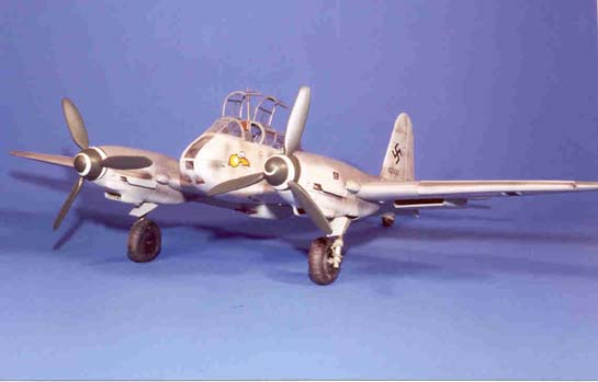
The result of all this work is to me a very nice replica of one of my favorite heavy fighters of WWII. Although they do require some work to complete, Scratchbuilders kits are in my view among the very nicest of the resin kits available. I recommend them.
© Frank Mitchell
This article was published on Wednesday, July 20 2011; Last modified on Saturday, May 14 2016