
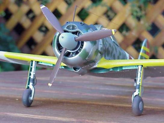
Revell Ki-43 Oscar
By Mark Mallinson
Nakajima Ki-43-II-Otsu
1 Hoki Sentai, 1 Chutai
Shimodate, Japan, 1943
Introduction
The kit presented here is Revell's vintage 1/32nd scale Nakajima Ki-43-IIb Hayabusa. After a quick Internet JPEG hunt, I could see that this kit would never be a truly accurate representation of the Imperial Japanese Army Air Force's Type 1 fighter, but with some work, could be brought much closer to the real thing. This process involved two main areas of modifications, and I learned a few new techniques along the way that my fellow modelers may benefit from seeing.
Aircraft History
Even while Nakajima's successful Ki-27 (Nate) was still coming into service, the IJAAF order a replacement aircraft encompassing all of the Ki-27's dog-fighting maneuverability, but with improved range and 300+mph speed. The Hayabusa (Peregrine Falcon, code named Oscar) began entering service a few months prior to the beginning of the Pacific War, and was not at first regarded favorably by its pilots. The addition of combat or "butterfly" flaps vastly increased the Oscar's flight envelope and then it became popular with its pilots.
At the war's outbreak, this slender, lightly armed and built aircraft proved itself in combat against inferior Allied designs. But as new US fighter designs like the F6F-3 Hellcat came into service, it became apparent that the late thirties Japanese design philosophy of light construction and high maneuverability could not compete with rugged construction, heavy firepower and speed of its newer adversaries. Despite this, the Ki-43 went through three main types and several sub-variants and soldiered on through the course of the war, never to gain the fame of Mitsubishi's A6M Zero.
The Kit
Revell's Oscar kit is vintage 1974, with all the features you would expect from that era: raised panel lines, generic interior details and an OK engine. The overall shape and size appear to match the Oscar. The one aspect of the kit that really took me back to my youth was the Revell Master Modelers Club entry form on the side of the box. Oh, what I'd give for one of those iron-on club patches now!
Interior Modification Process
Using AeroDetail #29 and JPEGs gathered from David Pluth's great Japanese Aircraft web page, I immediately discovered that Revell's cockpit bore little resemblance to reality.
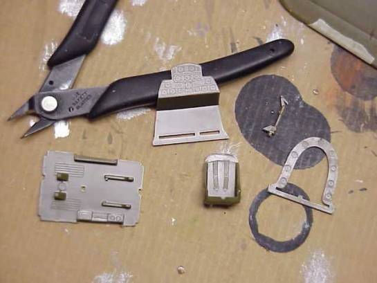
Original Cockpit Parts
The modeler is given 5 parts that include a seat that is the wrong shape and around 30 scale millimetres thick. The instrument panel also bears no resemblance to any Ki-43 panel photos and their foot pedals were two slanted blobs on the floorboard. The stick was wrong, but had potential for correction. The two fuselage halves had some adequate raised stringers, as well as some erroneous and shallow side wall equipment boxes.
The first modified item was the instrument panel, which was sanded off. A drawing in AeroDetail #29 of the type IIb's instrument panel was photocopied and reduced to 1/32nd scale. This pattern was used to cut out an instrument panel from .010" thick sheet styrene. Details like the instrument dials and the angled radio control panel were measured on the paper reproduction and transferred onto the blank panel. A separate radio panel and supports were made from more styrene sheet. A piece of .010" sheet was thinned to ~.005" and a Waldron punch and die set was used to make round dials and knobs. Rather than trying to accurately punch each of the round instrument dial holes in the panel, I found it easier to mark the general location, then drill the hole by twisting a #11 blade until I started to approach the right size. By biasing the blade to the correct direction, I could adjust the location of the holes until they were close to where I wanted them. Waldron round instrument bezels were added around the nearly finished dial holes.
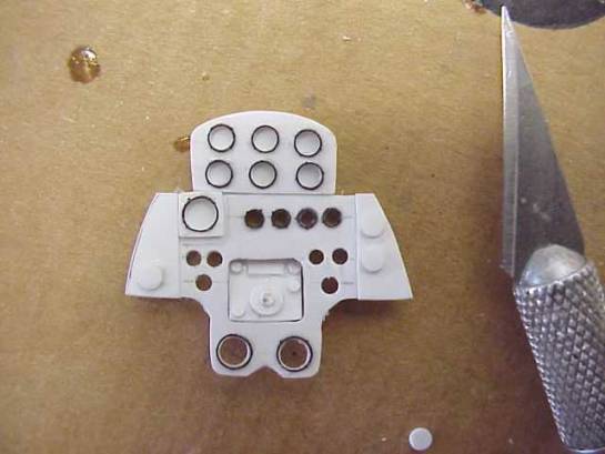
Custom Type IIb Instrument Panel
After painting with Polyscale dirty black and dry brushing with neutral gray acrylics, Waldron 1/32nd instruments were punched out and glued to the back of the new panel with white glue. Other small details like the compass and the choke primer hand pump were made from various leftover scraps and punched disks. The 12.7mm machine gun breaches were taken from the Hasegawa F-86 and supported with scrap pieces of sheet.
As mentioned earlier, the seat was very thick and the wrong shape. The faint molded seat belts had to go, so I started thinning and re-shaping the seat from "boxy" to something closer to reality. I also drilled out the three sets of holes and added thin strips of styrene for stiffeners in the back of the seat. I painted the seat in natural Tamiya flat aluminum, though that may have been the wrong color for a Ki-43-IIb.
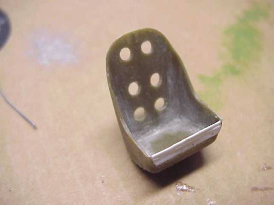
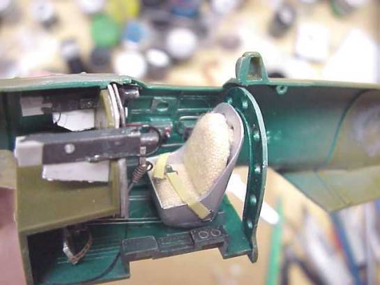
Modified Seat
Based on photos of the Alpine Fighter Collection Oscar I, I added a rear seat pad and parachute. These were made from a core of 1/8" thick silicon rubber sheet and sections of gun barrel patch cloths stained a light beige/brown using black Russian tea. The fabric was super glued to the hidden sides of the two rubber parts and the parachute pressed into the seat bucket. The rear seat pad was held in place by taking two strips of stained fabric, gluing them near the top/rear of the pad, then threading them through the top and middle set of lightening holes in the seat back. The strips were then glued to the bottom of the pad and secured. Waldron seat belt buckles and (inaccurate) belts from Tamiya tape finished off the seat.
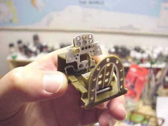
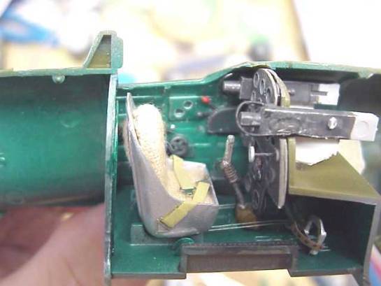
Finished Cockpit Tub Prior to Installation
It was now ready for painting and it couldn't have happened at a better time. Just before I was ready to try and paint Otakae, Gregg Cooper published his detailed Gekko painting article on Hyperscale. I used this technique with a 60/40 mixture of Tamiya clear green/ clear blue on top of brushed-on chrome silver over neutral gray primer. After washing with diluted black and dark brown enamels, it gradually started to look OK.
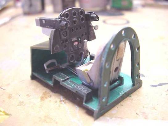
The cockpit sidewalls were dressed up with equipment boxes and cables made from styrene sheet and copper wire and solder. The faces of some of the boxes were given Waldron placards from my spares box, while a piece of sprue was shaped into an oxygen bottle. The floor was cleaned up, and foot pedal blobs removed. Using AeroDetail, I made foot pedals out of steel wire, styrene and masking tape for straps. A hole was drilled in the floor where the center would pivot. Control cables from the pedals were attached to a hidden rod that was glued to the seat supports. The control stick was modified with a gun actuator cable and simulated leather boot at the bottom made from painted tape.
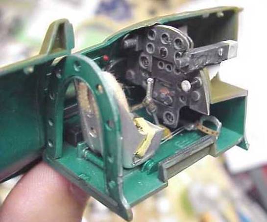
Finished Interior with Right and Left Side Walls
Engine and Exhaust Modifications
Once the interior was done and the two fuselage halves glued together, then it was time to tackle the engine. Once again, I used AeroDetail #29 to supply some good photos. In addition, I got some good detailing ideas reading Pat Donahue's 1/48 A6M2 article in the September 2000 issue of Aircraft In Miniature. The Oscar was powered by the Ha-115, which was Nakajima's version of the Mitsubishi Zero's Sakae engine. The kit supplied eight engine and exhaust parts: two rows of cylinders split fore and aft, a push rod and gear assembly and an additional magneto head (or whatever it's called?). The exhausts were represented by the last 10-12 inches of their thrust producing tubes.
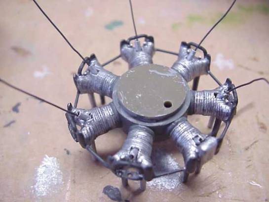
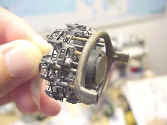
The first step was to glue the cylinder halves together and sand off the molded-on ignition wires and seams. This left bare cylinders without any cooling fins, so I re-scribed all the cylinders with a #16 hobby knife. The spark plug detents in the heads were drilled to accept wires. Based on my references, I needed to make two missing brackets for each cylinder and an additional strut between each cylinder. The first was a U-shaped bracket that protrudes out the top/front of each head. The second bracket is a sort of ignition wire harness that fits on top of each cylinder head and has two holes. Using strip styrene and solder, I used a little trial and error to produce the correct shapes and then used them as masters to repeat that at least 14 or 15 times (never hurts to have spares). Both sets of brackets and struts were then CA glued into place and the assemblies primed with neutral gray. The cylinders were eventually painted with Tamiya flat aluminum and washed with diluted black enamel while the valve covers, brackets and struts were painted dirty black. In the end, the 6 kit engine parts became over 100!
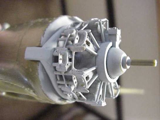
Primed and Dry-fit Engine and Exhaust
The spark plugs were made from 2 -3mm lengths of styrene tube and their 20-30mm long ignition wires from painted copper wire.
Installing Spark Plugs and Ignition Wires
Because I had opened the cowl fins, I had to complete the exhaust collector. This was made from the two kit exhausts and the leftover ring of sprue that surrounded and supported the push rods. This ring was sanded and cut to length and glued together. Then the exhausts were tacked into position and glued. Very thin strips of Evergreen sheet were glued around the ring/exhaust interface to build up the flared shape. The nice thing about using this material was that when covered with Testors styrene glue, the soft Evergreen strips would almost liquefy into a thick white slurry that could be shaped to better fill gaps. When finished, the collector ring was primed, then painted first with steel enamel, then Model Master burnt metal, then a wash of thinned rust acrylic to give it that used and weathered look.
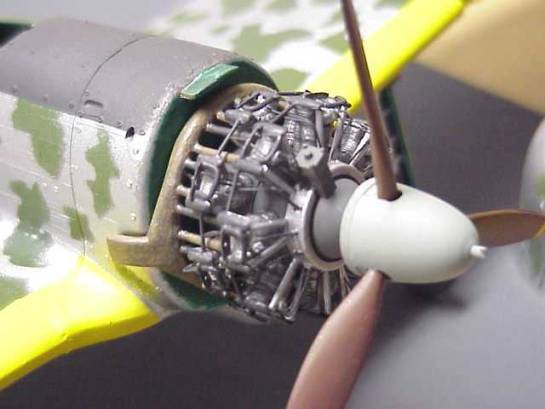
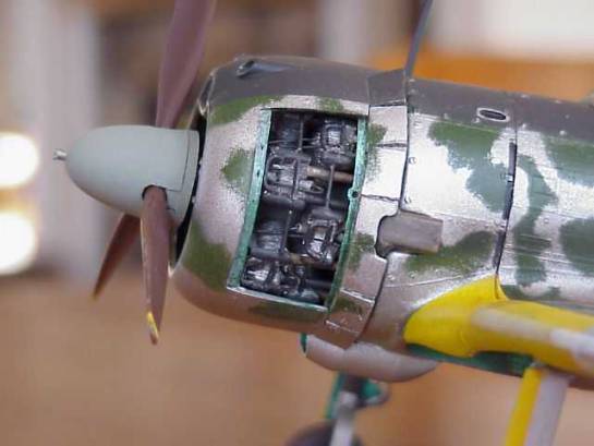
Installed Engine & Exhaust
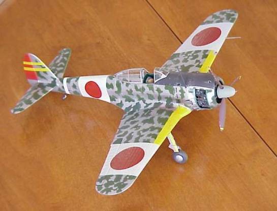
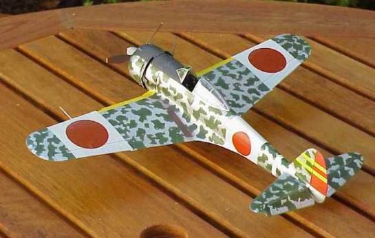
Exterior Paint Scheme & Technique
The paint scheme chosen for this aircraft came from Richard J. Caruana's article in the September 2000 issue of Scale Aviation Modeler International. I liked the green mottling on bare aluminum and this aircraft had the right color combinations for the Oscar IIb. In addition, I used the Schiffer monograph on the Oscar for the proper wing and horizontal stabilizer patterns.
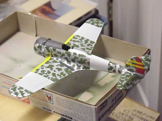
The technique used to paint the outside of the aircraft is some times called "reverse mottling". The aircraft was first primed using light gray acrylic. This also helps to see and repair any defects in the puttied seams prior to the color coats. Then flat white was sprayed over the vertical tail, fuselage and upper/lower wing areas where the white home defense bands are located. The yellow horizontal tail stripes and wing IFF bands were painted with Tamiya bright yellow. These were then masked and the rest of the tail's control surface was painted with insignia red (a bit too bright, but OK for me). When cured for a day, the tail, IFF bands and home defense bands were masked and the plane was ready for the main paint job.
The reverse mottling technique requires spraying the darker mottling color first, then masking it off and spraying the natural metal over it. To this end, I sprayed a coat of Tamiya dark green in an uneven coat, lightening the color on top of the fuselage and here and there on the wings. When cured, I sprayed Future over the green to seal and smooth the surface. Then the tedious masking process began with 1/32nd scale photocopies of the Caruana and Schiffer planes and a product called Handy-Tak which like Blue Tack, can be used to hold down the paper masks onto the plane without leaving an oily residue behind. The green paper mottling was cut away from the aluminum (my wife says I'm making paper dolls) and was held onto the model with very small pieces of Handy-Tak, leaving a 12mm gap between the model and the masks. It took the better part of a day to cut out and affix all of the paper masks.
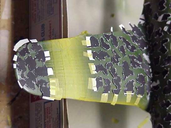
Paper Mottling Masks
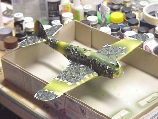
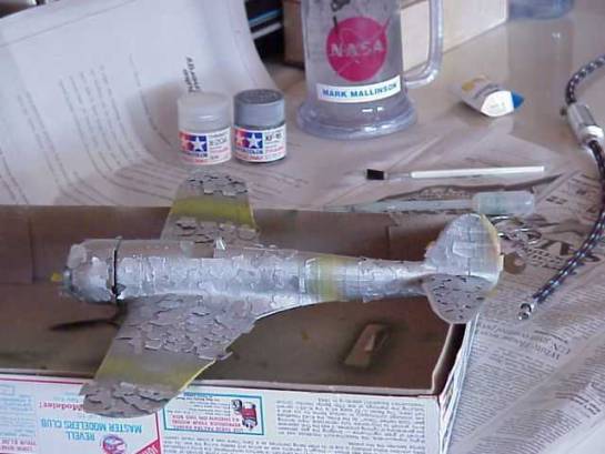
The next day, I checked all of the masks and then sprayed the entire model with Tamiya flat aluminum using 10-15 psi through my old Paasche H airbrush. I had hoped that the low pressure would help to give the masked areas a bit more feathered edges. When done, I carefully removed the masks to find that the technique more or less worked. The anti-glare and walkway areas were then masked and sprayed with Polyscale dirty black. When all the masks were removed, then it started to look like what I wanted.
Pre-Decal Paint Job
Final Details
Prior to decalling, the wheel wells and covers were masked and sprayed with the Otakae mixture. Lightening holes were drilled into the oleo scissors as seen in AeroDetail. Then brake lines were fashioned from steel wire and painted black and flat aluminum. These were installed with the use of CA glue and aluminum foil strips used as hose clamps. After the landing gear was installed, the rest of the brake line wires were bent into the gear bays and glued into place.
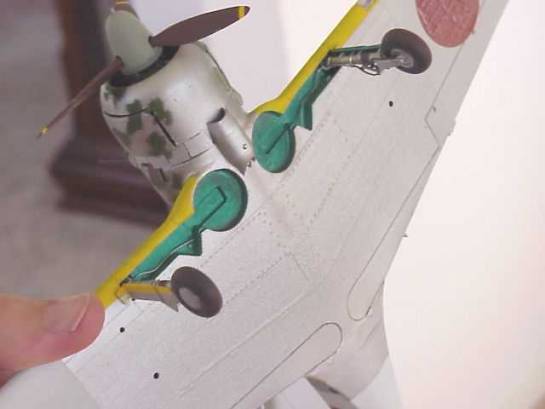
Finished Landing Gear and Wheel Wells
The decals used for this project included the Revell kit hinomaru for the wings (big mistake) and some smaller AeroMaster hinomaru used on the fuselage. The AeroMaster decals reacted well to Micro Sol and looked painted on. The Revell hinomaru decals didn't react at all to the same procedure and may wind up being removed and replaced with painted meatballs. Final weathering was done with Tamiya Smoke, thinned enamel washes and ground pastels.
In retrospect, the Hasegawa kit has many advantages over this old thing, but it did afford me the chance to learn some new painting and detailing techniques along the way. The end product looks like an Oscar, and the engine and interior details make it look like a better kit than it is.
References
- AeroDetail No. 29
Nakajima Ki-43 "Oscar", November 2000
ISBN 4-499-22735-6 - Bueschel, Richard
M., "Nakajima Ki-43 Hayabusa in Japanese Army Air Force RTAF-CAF-IFSF
Service" Schiffer Military History Book, 1995
ISBN 0-887740-804-4 - Caruana, Richard
J., "Peregrin Falcon from the East"
Scale Aviation Modeler International magazine
Volume 6, Issue 9, September 2000 - Cooper, Gregg, "Gekko
Part One: Building Tamiya's Nakajima J1N1 Gekko (Irving) Straight Out
Of The Box"
Brett Green's HyperScale web page - Donahue, Pat, "Mitsubishi
Zero Model 22"
Aviation In Miniature magazine
Volume 1, Issue 2, September 2000 - Mikesh, Robert C.,
"Japanese Aircraft Interiors 1940-1945"
Monogram Aviation Publication, 2000
ISBN 0-914144-61-8 - Wlodarczyk, Mark
T., "Camouflage & Markings of IJA Type 1 Fighter Hayabusa:
Oscar", 1996-1998
Dave Pluth's Japanese Aircraft page j-aircraft.com
This article was published on Wednesday, July 20 2011; Last modified on Saturday, May 14 2016