
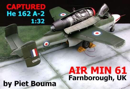
Revell 1/32 Heinkel He 162
By Piet Bouma
1 – THE AIRCRAFT
When Revell brought out the 1:32 scale Heinkel 162, I decided this would be my third building project, after the Ta 152 had been completed. Internet reviews and here at LSP, Christian Kirchhoff’s “In the Works” Report on his “Gelbe Drei” (Yellow Three), have helped a lot! In fact, Yellow 3 was captured at Leck, Germany in May 1945. It was flown by Lt. Gerd Stiemer in the 3rd Gruppe of JagdGeschwader 1 “Oesau”. Later it became “Air Min 61”, so you could say in a way I captured Christian’s “Gelbe 3”… As far as Revell’s model is concerned, I think it’s an excellent model with only minor changes needed; it’s affordable and of a very high standard for that price!
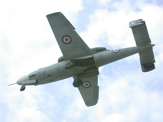
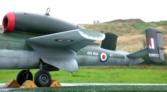
Since most people build the German aircraft in the state they were captured in, I wondered how the aircraft looked like after the British had taken them over at the end of the 2nd World War; the RAF roundels and fin-flash would certainly add some colour…
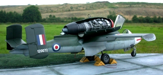
To my knowledge there’s only one photograph of 120072 as “Air Min 61”; it was taken at Farnborough (UK), where the aircraft was test-flown by the RAF. The aircraft crashed during one of these flights. Unfortunately the RAF test pilot lost his life…
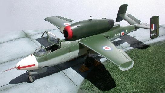
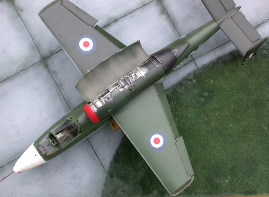
Air Min 61 has been described as a He 162 that was sprayed in only one shade of green (RLM 81), with RLM 76 on the lower fuselage and under its wings. Official RLM requirements were that the aircraft should be in two shades of green: RLM 81 and 82, of which 81 is the darker one. Fuselage (upper part) and left wing would be painted in RLM 82, whereas the removable engine covers as well as the right wing were to have RLM 81. (Many sources state that it should be the other way around, but a colour photograph on the internet confirms my turning around of these colours; an internet link is provided at the end of this article.)
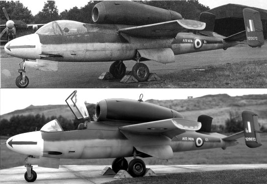
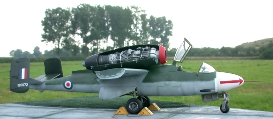
To contribute to the (never ending) discussion about RLM 81 / 82 / 83; I’m convinced that Air Min 61 (previously Yellow 3) was painted according to RLM regulations, which means it too has two shades of green. In the black and white photograph you can see a slight difference in tone between the engine cover and the upper fuselage colour, which is lighter. The tail also seems to be in a darker green (like the engine cover). The top coat lacquer causes the upper fuselage and upper part of the elevators to reflect the sky above. (The photograph I mentioned has been reproduced several times and appears in as many tonal differences because the quality of the print wasn’t always high… In some cases it looked like a light grey colour was used on the upper part of the rear fuselage; this is an optical illusion caused by the reflections being over-exposed during printing…).
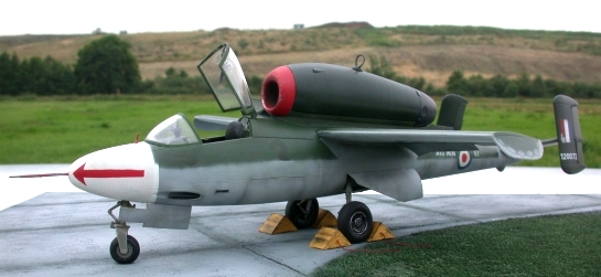
The overall look of the plane can vary a lot, depending on weather and time when taking the photograph. I have experimented with these factors and conclude that the original photograph of Air Min 61 was probably taken late afternoon / early in the evening with an overcast sky. I’ve photographed my model under the same conditions (outside) and have the impression that the result in comparison to the original is quite acceptable (Black & white photograph above.). Which doesn’t mean the two-tone green upper camouflage question has now been solved, it merely offers the possibility of looking into the matter again in a new perspective. Also, do have a look at the tonal differences in my photographs taken in sunnier conditions; the difference is rather interesting… (And it’s always the same aircraft…)
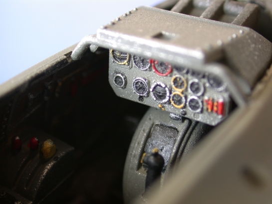
2 – THE COCKPIT
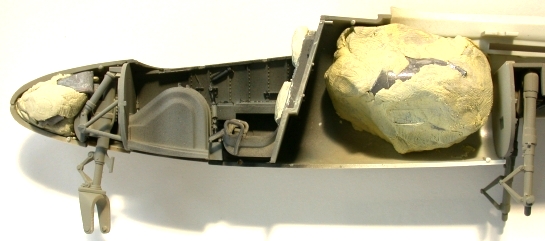
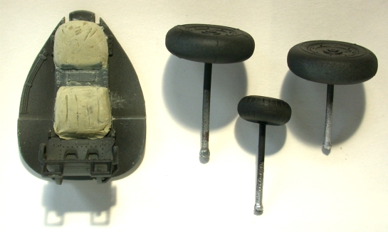
Thanks to Christian (who pointed out the necessity of putting the correct weight in the nose and in the area right behind the cockpit) there was no balance problem! I tackled the problem with lead and Tamiya putty, to keep this lead in place. The only scratch-building I did were the seat cushions; they were shaped with Tamiya putty.
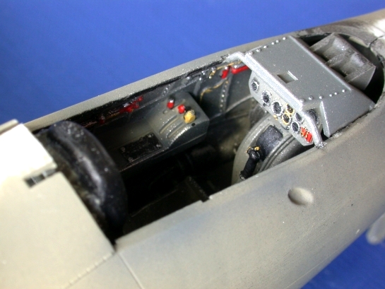
I airbrushed the entire cockpit (and fuselage halves) in Revell Matt 45. Then I applied vertical lines of Matt 77 (+ a bit of white). The instruments received reasonably thinned drops of matt black. After a drying time of a day or two I drybrushed them with yellow, red and silver (Revell 66 or 99?); I used a very fine brush. This is the first time that I succeeded in painting a proper cockpit instead of ‘a black hole’ as in my previous two builds (Bf 109G and Ta 152H)… It must be said, you learn a lot in the Forums at LSP! (Cheers, guys!)
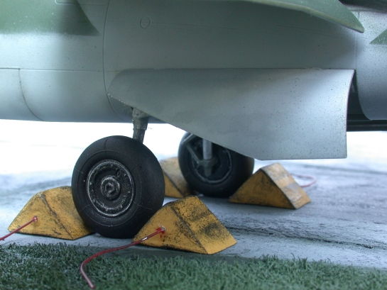
In the picture you see my way of holding the wheels during the airbrushing process. When you’re painting the inner parts of the wheels, you don’t have to wait for the other side to dry; you can do both sides after another… Wheels and tyres received a coat of matt 77; the sides of the wheels and tyres received a mixture of matt 8 and 9 + a bit of matt 78 (this was sprayed onto the wheels from straight above). The inner parts of the wheels were airbrushed glossy black (Main Landing Gear, or MLG) and RLM 02 for the NLG, the Nose Landing Gear. The part where the wheel and tyre meet received a drybrushed silver in order to approach the look of the wheels as in the original photograph. The tyres kept the somewhat greyish appearance in the area where the tyres touch the ground when rolling…
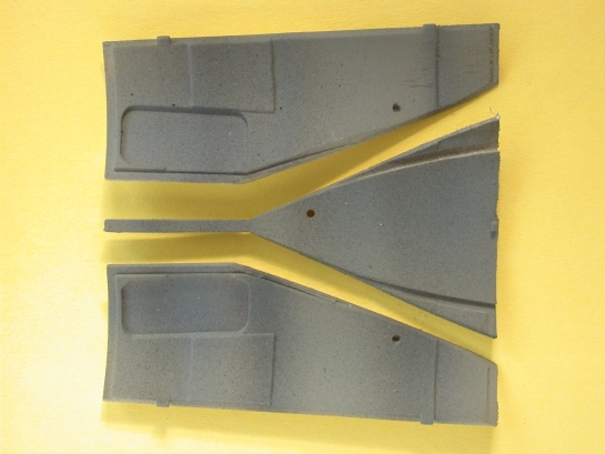
3 – MAIN LANDING GEAR DOORS – WARNING!
The Main Landing Gear doors are rather a problem in the Revell kit; the risk of putting them onto the model in the wrong direction is quite understandable. The kit instructions do not point that out clearly.
There is however, another problem; the shape of these doors is not completely the same as that of those on the original aircraft… In fact, the curve of the longer lower part of the MLG doors should be a straight line! In the photograph below you can see that it can easily be corrected by cutting off the curved parts along a metal ruler. Then glue these remains to the centre part (of the fuselage), so that this becomes a correct triangular part (which will be glued to the fuselage afterwards).
So, you see; comparing the model’s shape to the original by means of photographs may even turn out to be more important than “counting all those damn rivets”… There are lots of aftermarket goodies for the He 162, but I haven’t seen these MLG doors yet… If you correct these on your model it will surely look better…
4 – MASKING AND AIRBRUSHING
The entire He 162 was airbrushed Revell Matt 45 as a base colour. Then I applied the RLM 76, 81 and 82 as mentioned above. My mixing formulas:
- RLM 76 - Revell SM374 + lots of Humbrol Matt 44 (white), so that the grey colour has a whitish appearance
- RLM 81 - Revell Matt48 + Humbrol Enamel 150 (equal amounts) + a bit of matt black
- RLM 82 - Revell Matt48 + Humbrol Enamel 150 + Revell Matt46 + a bit of Revell matt 68 (First three colours mentioned: almost equal amounts; a bit more on the 46 and a bit less on the 48)
Weathering effects on RLM 76: pre-shading certain lines with Revell Matt 45 (which comes close to RLM 02), then partly overspraying with RLM 76 + a bit of Revell Matt 57.
Weathering effects on RLM 81 and 82: same colours oversprayed (+ a bit of white added)… The original German “Yellow 3” and squadron badge were oversprayed with “RAF dark green”, which brings us to an intriguing question; Where was the real Air Min 61 oversprayed? Probably at Leck airfield, Germany!? Did the British use German paint or as I presume, RAF paint? Did they bring that in from England on a transport plane? Who can shed a light on this..?
The top part of the fuselage and the tail wings reflect a lot; therefore I decided to seal these parts with a glossy top coat lacquer; Revell clear gloss. Then I applied the only decals I used: the numbers “120072”. They were sealed with Revell clear matt (like the rest of the aircraft was treated with), which turns out as a sort of satin coat over the greens and as a reasonably matt coat over the RLM 76…
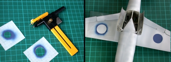
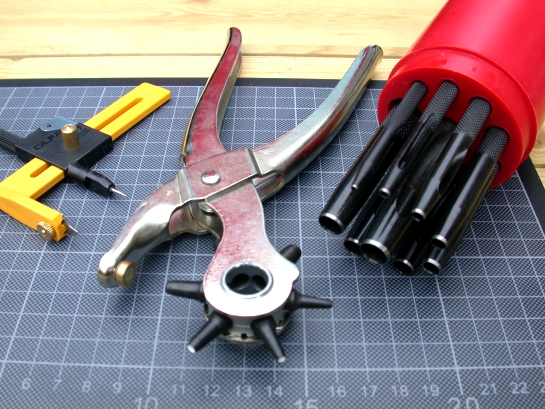
Since the aftermarket decal sets weren’t available yet when I started on this model, I decided to try and spray the roundels myself (before the matt lacquer was applied…). I’m quite pleased with the result, but I wouldn’t do it again in the way I did. I used an OLFA Compass Cutter CMP-1 (for cutting circles from 1 to 15 cm). I now know it’s perfect for the larger circles, but for the smaller circles this CMP-1 is no good; the masking tape is a bit elastic and changes shape when you’re turning the compass cutter… You’d better buy a tool for punching circles (of different sizes) in clothing; in belts, etc… Or you could buy a hollow punching set, which comes in different sizes. You use a small hammer for punching out a nice circle in your masking tape. (See photograph further down; from left to right: CMP-1, the belt-hole-puncher and the hollow punching set…)
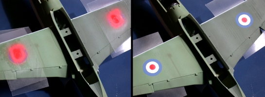
For the RAF roundels I started with the widest circle and airbrushed the entire circle blue. Then I airbrushed the white colour, after which the central red circle finished the sequence. (Blue – Revell Matt 56 / White – Humbrol Matt 34 / Red – Humbrol Matt 153) The sizes of the roundels were educated guesses; I measured them in original photographs and compared these values to (typically British) inches. For the fuselage roundel I used the scale equivalent for 18’’ (inches in reality) and for the wings I used the scale equivalent for 25’’. The latter however might even have been 26’’ or 27’’ in reality (but that’s always afterwards, when comparing the finished model to the real aircraft…). Photographs of the aircraft from above with British roundels are unfortunately not in my possession… So I guess they would be the same size on the upper side as on the lower side of the wings…
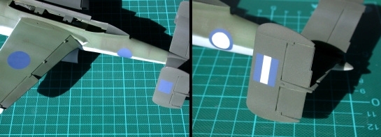
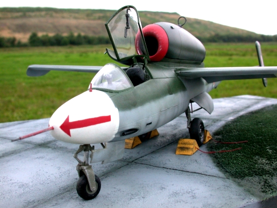
The fin-flashes were airbrushed in the same order; but be aware that the red colour is always on the side closest to the front of the aircraft! (Which means: from left to right on the left side of the aircraft, you have red first, then white and then blue… / On the right side of the aircraft you have (from left to right:) blue first, then white and then red..!). The arrows on the (Matt 34 white) nose are also airbrushed in Matt 153 Red…
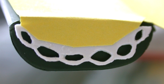
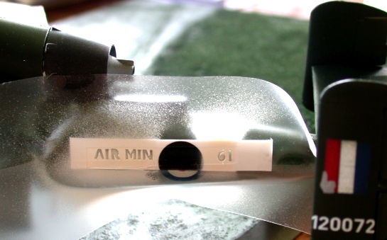
Air Min 61 has this typical wavy pattern on its downward pointing winglets; I designed a special mask for them by using plastic sheet.The “AIR MIN 61” text was cut out from and airbrushed through photographic printer paper, because of the elasticity problems caused by masking tape (as mentioned earlier)…
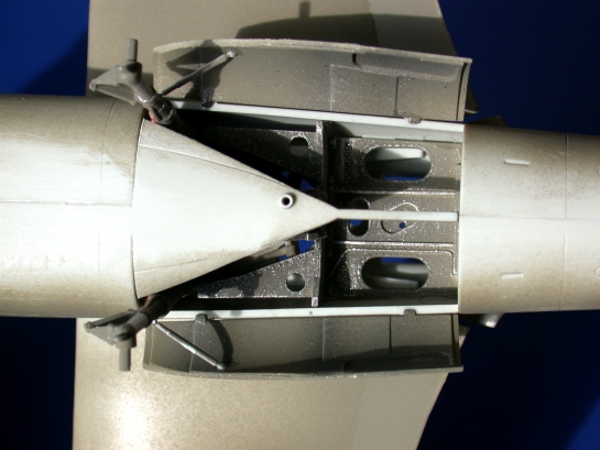
5 – ENGINE AND ENGINE COVER / FLAPS, AILERONS & RUDDERS
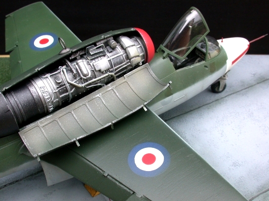
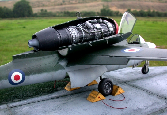
I wanted to be this engine a real showcase, so I put a lot of extra effort in it. I used thin metal wire, electrical wire and white glue to enhance the engine according to photographs I found on the internet. The engine was airbrushed in different silvery colours and black where necessary before I added the extra wires, etc…
Plastic sheet was used for the clamps on the engine cover. Some drybrushing with silver and black did the rest…
The flaps, ailerons and rudders were cut out of the wings and glued into position. With a sharp hobby-knife you have to start with cutting out the hinges; I had the knife in an almost vertical position and started cutting the 90 degree corners first. Then I repeatedly went over the straight lines until the entire flap, aileron or rudder came loose… WARNING! These surgical hobby-knives are very sharp! It’s dangerous when cutting and using force while doing so… You should wear safety glasses as well…The good news: it’s cheaper than the aftermarket stuff and it’s probably nearly the same quality as well. If things do break off however, you can still repair a lot with putty… It’s worth the effort of putting ailerons, flaps and rudders in other positions than neutral, because your model looks like the pilot has left the aircraft as it was and will be coming back soon… (Ailerons should be put in opposite directions; when the one on the left is deflected upwards, the one on the right should be hanging down, of course… The stick should be tilting a bit to the right in the cockpit then…)
Internet link to He 162 colour photograph
(Note the yellow wheel chocks, which have probably been borrowed from a Spitfire… In Air Min 61’s case you can see horizontal lines running over the chocks. This probably denotes that these chocks were interconnected by a wooden plank in earlier days; The Spitfire’s wheels were further apart than the Heinkel’s, so the plank had to go away… In the case of the Spit, connected wheel chocks only required pulling once and you needn’t pass under the nose for the other chock, which meant you could stay well away from a turning propeller. Safety first!)
Happy modelling!
© Piet Bouma 2005
This article was published on Wednesday, July 20 2011; Last modified on Sunday, June 10 2018