
Pacific Coast Models 1/32 Macchi 202 Folgore
By Brian Thoresen
The Pacific Coast Models Macchi 202 was released by Ken Lawrence about five years ago, and was hailed as filling a major gap in 32nd scale World War Two fighter collections. Because of PCM, the Italian Air Force has finally been getting some representation after being ignored by many kit manufacturers for many years. I had built the old Craftworks kit years ago for a client, and always wanted to build a Macchi of my own. The Craftworks kit was a nightmare, and I figured even a limited run kit such as this would be a quantum leap in fit and finish. What I did not anticipate was this project turning into a bit of a 5-year “Magnum Opus”, in turn fighting me at every step of the way.
I have prepared this article in the hopes of helping some modelers that might have this kit in the stash, but are reluctant to build it because of the kit’s build reputation. I will do my best here to describe the necessary steps I had to take to get the model to completion. Many of the issues were of my own making; some were shortfalls of the kit itself. But being that this was only PCM’s second attempt at a kit in this scale, I could not be too hard on them (their later efforts are light years ahead of this one) Being that this is a five-year build, I will try to be as accurate as I can on recalling the problems I encountered.
Let us begin…
Cockpit
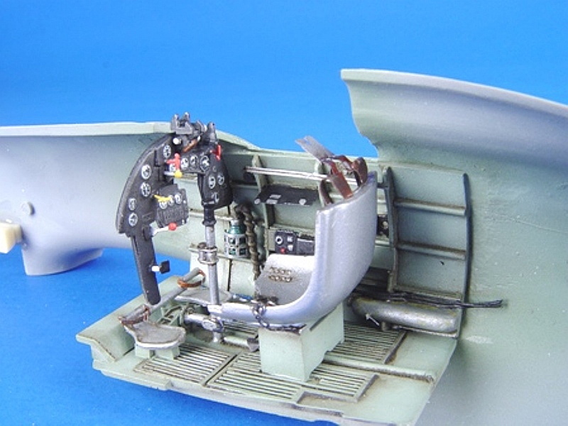
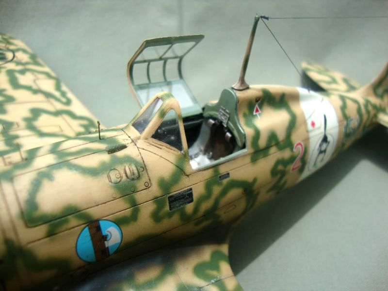
As with most single engine fighters, I started with the cockpit. I started by building the instrument panel, which is a mix of plastic, resin and photo-etch parts with film instruments. The parts locations are a bit vague, so pay attention to the instructions. I assembled the panel according to the instructions, masking the individual instruments with liquid masking agent for painting. The panel gets a ton of tiny photo etch levers, which I added a drop of Kristal Kleer to give those more of a 3-dimensional feel. I primed the panel with Alclad grey primer, as I find this is resistant to handling, and also grips to brass well. The panel was then painted in flat black and washed/dry-brushed. The handle ends were painted with various enamel colors to liven it up a bit.
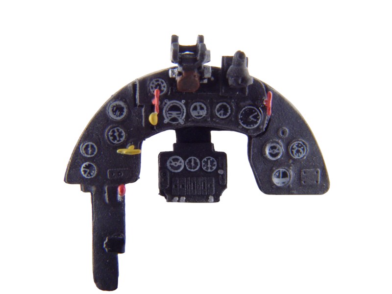
One problem I ran into was the liquid mask had fused to the instrument faces (Possibly from the hot primer), so I ended up using decals from my spares box to replicate the instruments. A drop of 5 minute epoxy was used on each face to replicate the instrument glass. The resin gunsight was assembled and painted, with acetate reflectors made and attached. Be careful here, the gunsight mounts toward the right side of the mounting location on the panel.
I moved onto the cockpit floor, which had a few small issues. First, the cast-in slots for the resin seat base, part # PUR15, are too short…I needed to carve them out and elongate them a bit to get it to sit correctly on the floor. Also, take the time to grind away all of the resin casting block on the bottom of the floor. If you do not do this, it will cause the lower wing to not fit correctly when it comes time to join it to the fuselage. I discovered this after everything was assembled and painted, and had to grind on the underside of the floor with a motor tool to thin it out. Hair-raising to say the least!
The fuselage halves required serious grinding to allow the resin sidewalls to fit properly. They were ground to the point of light shining through the thin plastic! Also, dry fit all of the cockpit components before committing to glue. Dry fit the seat/base, floor and sidewalls all at the same time. The resin sidewalls need to be mounted high enough to sit flush with the cockpit sills on the fuselage halves (This will also affect the lower wing fit later by pushing the cockpit floor down. You will also know that you have thinned the fuselage halves sufficiently when the floor and sidewalls fit, and the seat does not interfere with the sidewalls as well. I used 5 minute epoxy to glue in the sidewalls, because it gave me some time to adjust the parts, and also added some strength to the very thin plastic.
Once the sidewalls were in, I commenced detailing them. The trim wheel on the left sidewall, part # A19 was short-shot in my kit, so I had to use a resin wheel from a True Details 109 set I had lying around. Trim chains were made from tightly twisted copper wire, then flattened and installed. I also added some more wiring to the right sidewall, also adding an oxygen hose from solder and wire to the regulator. Most of the photo-etch parts that were to be folded and installed on the sidewalls were made from scrap styrene using the photo-etch parts as faces. I do not like folding photo-etch boxes, as they never seem to look solid to me!
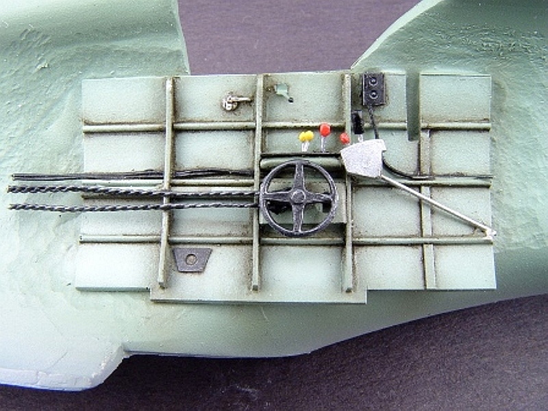
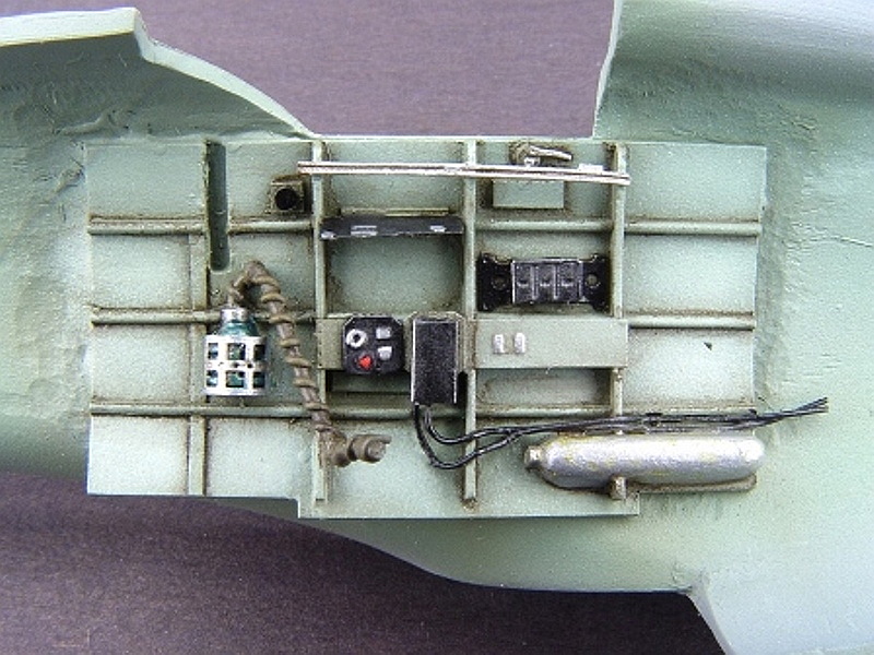
The cockpit was then sprayed with Model master RAF Interior Green as this is a close match to the green used in the Macchi’s cockpit. I then used a 50/50 mix of Interior green and white, and added highlights to the floor and sidewalls. The seat was sprayed aluminum, and the harness was painted dark brown and dry brushed with various oils to obtain a look of leather. All the parts were then washed with a Raw Umber oil wash, and then dry brushed with RAF Interior Green mixed with white oil paint. The various details were picked out in the required colors, and the parts were flat coated to seal everything in…
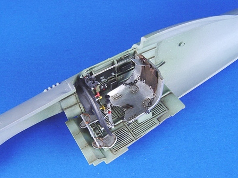
Before the fuselage halves can be joined, you have to install the resin exhausts. The good news is you do not have to remove them from their casting blocks. I did however have to enlarge the exhaust openings in the fuselage halves, and also this the surrounding plastic from the inside to get them to sit properly. 5 minute epoxy was used to affix them. Lastly, I hollowed out the leading edges of the exhaust shrouds to represent what I saw in reference photos.
I assembled the fuselage halves, using lots of clamps, and liquid cement to bond the parts. The parts in my example were slightly warped. I used Super glue to fill all of the seams, and rescribed as necessary. The turtle deck/spine area just aft of the cockpit was misshapen, so I had to reshape it accordingly. The lower nose cowling needs to be added after the wing assembly to ensure a better fit. I was however able to add the upper cowling, part A3, at this time. This part was slightly undersized so I shimmed it with styrene, and filled the seams with super glue and rescribed. The gun troughs are just hollow expanses on this part, so I took some artistic license and added some unused nose guns from a Hasegawa Bf 109G-6 to fill the openings. Their ends were hollowed before installation. The look of this area by this simple modification was much improved!
I took the time to carve out some of the scoops on the nose that were solid on the kit. I used a #11 X-acto knife, and smoothed out the openings with liquid cement. I also took the time to run a needle in a pin-vise through all of the panel lines to clean them out and make them a little more consistent before moving onto the wings.
The Wings/Lower nose
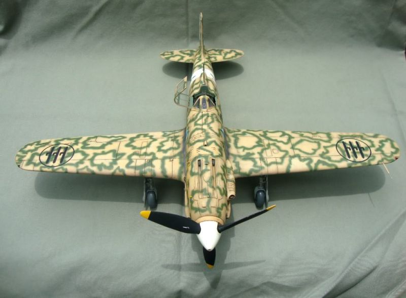
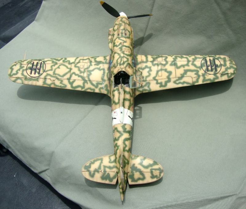
The wings presented their own challenges during construction. First and foremost, I had to thin all of the trailing edges of the upper and lower parts to more appropriate thickness. When it came time to assemble the upper and lower halves, I noticed that the upper wing parts were smaller than the lowers. This was a problem I did not anticipate. What I would suggest is tack gluing the halves together, sand the upper and lower profiles to match, then separate them and thin the trailing edges. Lastly you can now permanently glue them together.
The wingtip nav lights are too small as provided in the kit, so I scratched new ones from scrap clear sprue, and blended them. At this point all of the assembly seams were cleaned up, and the leading edges rescribed.
At this point I mated the wings to the fuselage. This was troublesome, as I did not spend any time dry- fitting the assemblies earlier on. What I found was huge gaps at the wing roots, with a large step at the trailing edge/fuselage underside joint. I ended up having to pack .080 of styrene scrap into the gaps. I glued it into place with ProWeld, trimmed and sanded flush to the wing surface. I then filled any leftover gaps with superglue, and rescribed as necessary. This area was a huge amount of work, and I feel that the problem could have been minimized with the use of a little dry fitting before the fuselages were permanently glued together. Take your time and dry-fit, dry-fit, dry-fit. You will thank me later!!!!
The last part of the wings involved adding tiny photo-etched hinge plates to the control surfaces. I used Future Floor Wax to glue them in place, which gave me plenty of time to position them properly. These buggers are tiny!!!!!!
At this point I attached the resin lower nose piece, PUR4, and found that the resin had shrunk considerably. It was too long, sticking out past the upper nose, and not wide enough where it mates to the lower wing/fuselage joint. Out came the Aves Apoxie sculpt, and I set about reshaping this part to match the nose profiles. I then rescribed all of the missing detail, and moved to attaching the oil cooler scoop, part PUR 6. PCM gives you some photo etch screens to add inside, a nice touch to be sure, but they do not fit inside the oil cooler housing. They are too wide. You will have to sand their edges, and dry-fit to get a nice result. The same holds true of the belly radiator assembly; the radiator screens were too wide to fit. Sand the edges and dry-fit. Do not add the plastic flow divider part inside the radiator until after paining, part no. A15. Lastly, I thinned down the trailing edge of the exit flap, part A11, to a more scale appearance.
The horizontal tail surfaces were next, and the fit was much better overall. I had to modify the elevators to an earlier Series VII style assembly, as the kit’s represent a later Series X style tail plane. I had used reference photos, and Ian Robertson’s excellent build article on Hyperscale.
Once the modifications were complete, I thinned the trailing edges of the elevators and installed them. I installed them with a slight droop, as most of the photos of parked Macchis show them in this configuration. The fit of the horizontal stabilizers to the fuselage was good, only needing light sanding to clean up the seams.
The rudder needed some attention to fit the vertical stabilizer. I had to add some scrap styrene to adjust the fit near the leading edges, as the gaps were too large. I also thinned down the trailing edge of the rudder as well.
At this point the model was starting to look the part, and this is where two of the biggest problems of this kit I faced came to light...
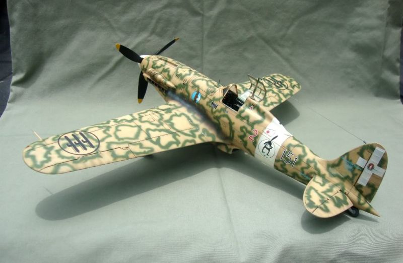
The Propeller
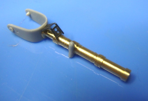
I had elected earlier to not use the wimpy plastic pin PCM gives you to mount the propeller, instead opting to use brass tubing to mount the assembly. I started to assemble the propeller as in the kit’s instructions, and noticed something was completely off. When I assembled the prop to the fuselage, I was horrified to notice the spinner was about 1/8” smaller in diameter to the nose! At this point I was turning the air purple over the bench, and decided to walk away for awhile.
Some time later, I decided to pack the back side of the kit spinner with styrene in an effort to bulk it out to meet the fuselage. When I did this, however, it totally changed the look of the prop by setting the blades to far forward away from their normal location. I also contemplated heat smashing a new one over the kit part, but that proved impractical. On a whim, I decided to try fitting the propeller assembly from the 21st Century Toys model of the Macchi, and low and behold- It fit, needing only a small amount of sanding on the nose to match the contour. Now, I am no expert on the Macchi, but the more I studied photos of the propeller, the more I noticed that PCM’s assembly seemed too small all around. The spinner was too blunt, and small in diameter, and the blades did not seem to be the right shape, and their chord width was too narrow. In short, a sheer act of desperation managed to make it look all the more the part. I was stoked!
Landing Gear
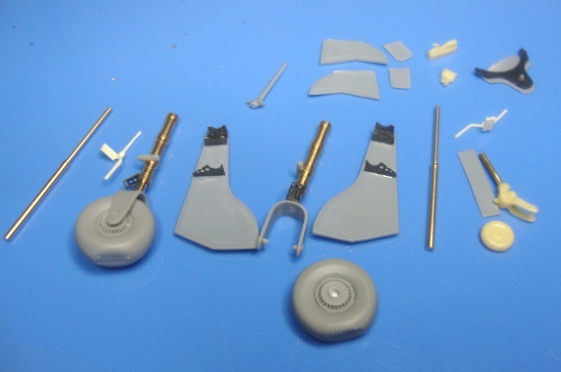
This area of the kit I managed to become stuck on for a long period of time, as it was, perhaps the most challenging aspect of this build. I will try to explain all of the issues with the kit parts:
The first issue is with the main landing gear struts themselves. They are appropriate in diameter, but unfortunately they are not round in cross section. They are more ovoid in cross section. If you try to straighten them out, you lose a bit of thickness to the gear, and with the detail on the struts, this proves to be impractical.
The next problem is the wheel forks. PCM elected to split the fork into two pieces, splitting them right below the centerline of the oleo. This is a big problem because of the main wheel assemblies. PCM has you assemble the wheel halves which are plastic, to which you add resin wheel hubs. The detail of these parts is great, but, the wheels as assembled are too wide for the wheel forks. This is a tough area to fix, as if you extend the separate wheel fork half parts, noC33 and C34, your wheels will not be lined up down the center of the strut. To be honest, it looks terrible! I played with this off and on for a year, and came up with various solutions that might work for others.
I managed to scratch build some main struts and forks from brass stock. I bent the forks from flat brass around the kit wheels, and made the struts from telescopic brass tubing. These came out OK, and with some more time, might be a viable option.
I also made a set from styrene tubing and stock, with a brass rod core. These came out ok, too, but I did not spend a whole lot of time on them, either (read, I am impatient!).
The model languished for a long time, until I heard Tail Boom Models released a main gear and wheel set for this kit, and I had to have it. The set arrived in perfect shape, and is exquisite. The main gear struts are turned brass, with cast resin wheel forks and wheel assemblies. These are direct replacements for the kit parts, and are a bit fiddly to work with. There are no instructions with the set, but take your time, and they come together well. The set also includes turned brass retraction struts, which replace the kit’s, parts C32 And C36. Those parts in the kit are devoid of much detail, and were really warped!
You will also have to modify the kit’s gear doors, as they are too tall to be used with this set. I cut material away from the top of them to get the proper sit on the struts. PCM gives you photo etch parts to fold and assemble to the gear doors that mate the parts to the gear struts. The instructions are vague here, so you will need to use the struts to position the gear door attachments before adding them permanently. Take your time, get all of the parts positioned where you want them before committing any glue here. If you do not, the doors will not sit on the struts properly, and you have a ton of work trying to fix it!!!!!
After the gear was finished, they were painted and weathered and set aside. At this point it was a simple matter of adding all of the remaining parts to the exterior of the airframe. I did have to fight with the fit of the windscreen, as it is a bit too narrow for the kit’s nose. I managed to get it into place, and filled the seams with superglue and putty. (The canopy was dipped in Future to prevent fogging.)
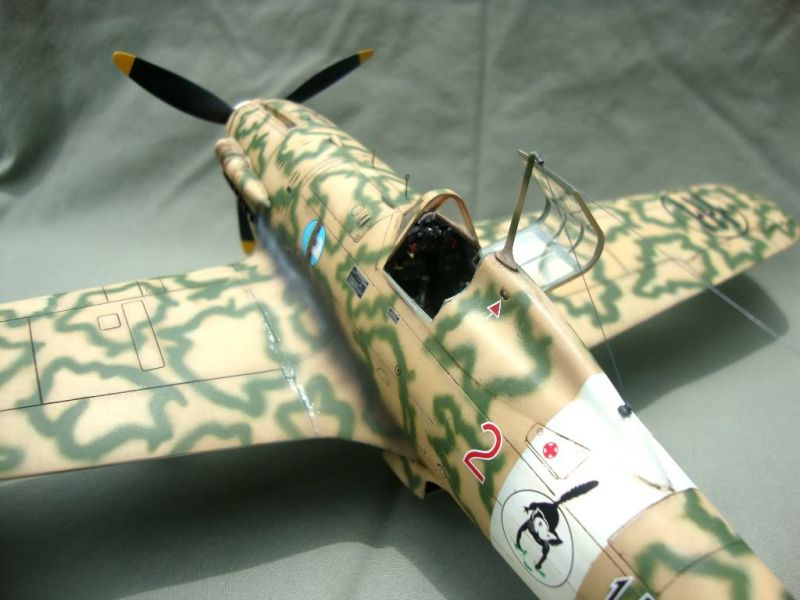
Paint and Markings
The model was painted with Model Master Enamels, thinned with lacquer thinner. I used a Paacshe VL airbrush with the paints thinned about 2:1 with thinner.
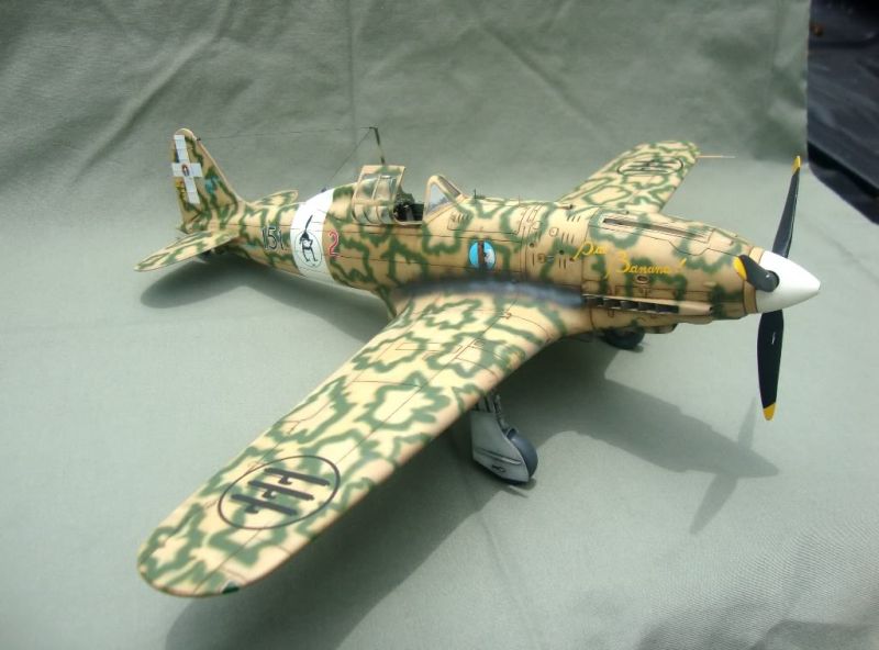
I began by priming the model with Model Master Gunship Grey. I then airbrushed the white fuselage band, and masked it when dry- A word of warning here- I should have also painted the Italian cross on the vertical tail, as the decals are translucent. More on this later.
I then used MM Aircraft Grey to apply a mottle to all of the insides of the panels. I then followed up with a 50/50 mix of Italian Blue-grey mixed with white to “marble the panels some more. I tried to be a bit random here, as I wanted to weather and fade the finish somewhat. I then applied a “shader coat” of straight MM Italian Blue Grey, mixed 30/70 with thinner to blend it all together, and get closer to the final shade I was after. This coat was applied in streaks, one area at a time to seem random. In the end, I had a nicely fished, although not too heavily weathered underside.
The topside base coat was done in a similar way, with the Gunship Grey Primer used as a base for shading. I mottled all of the individual panels with MM Italian Sand, which, incidentally, is not a good match for the real color. I followed that with some more mottling of MM RLM 79 mixed 50/50 with white for even more contrast. I then applied a shader of MM Italian Sand and RLM 79 mixed to a more accurate shade for the base color of the Macchi 202’s. This mix was thinned 30/70 with thinner, and sprayed randomly to blend everything in. The beauty of using the shaders is that blending comes slowly, so you have plenty of time to “tweak” the finish how you like.
I began spraying the smoke rings with Model Master Italian Olive. Unfortunately, the color was way wrong. I ended up using RAF Dark Green, which seems to mimic the real color better. I used a very thin mix, and very low pressure to achieve a smooth demarcation. I used photos as a guide to the positioning and sizing of the rings. Tarantola’s aircraft was photographed a lot, so most areas were done following the photos.
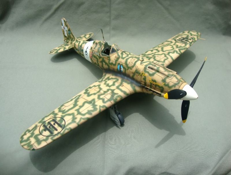
Once the base painting was complete, I coated the model with two coats of Future Floor Polish applied with a wide soft brush. This settled down beautifully, and I let the model dry for 48 hours.
Once done I applied the kit decals according to the instructions. They appear to be printed by Cartograf, having good coloring and register. However, I found that while applying them, they did not seem to like to be adjusted once they hit the model’s surface. I found that applying them to the model’s surface, heavily wet seemed to be the trick. Everything snuggled down with a bit of Micro-Set and Micro–Sol.
Once dry, I over coated the model with Future again, and once cured, started the weathering. I applied a wash of Raw Umber oil paint, thinned with Testor’s Brush Cleaner to all panel lines. I wiped the excess off in the direction of airflow. By using the brush cleaner, it allowed me to remove the excess without disturbing the Future coat. Exhaust staining was applied using a mix of brown, black and grey enamels applied with the airbrush.
The last step was to install of the fiddly bits, including the gear and doors, antenna, and canopy.
Conclusion
After five years off and on again work, I was glad to complete this model. Not sure why it took so long, but it did. Life has a funny way of getting in the way sometimes. The kit is a tough build, but is currently the only available choice for those fans of the Folgore. If you manage to avoid some of the pitfalls with the build you will be rewarded with a nice representation of the Folgore. Hopefully this article will help some who have been avoiding this kit.
Happy Modeling!
Brian “Thor” Thoresen 2011
This article was published on Saturday, November 19 2011; Last modified on Saturday, May 14 2016