
One Man Model | 1:32 Hawker Siddeley HS780 Andover C.Mk 1
Reviewed by Iain Ogilvie
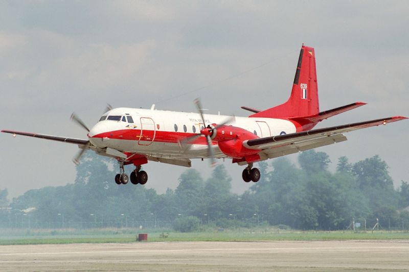
Hawker Siddeley HS 780 Andover
At the start of the 1960s the Royal Air Force (RAF) issued a requirement for a medium tactical freighter and Avro started work on a military variant of the Rolls-Royce Dart-powered twin-engined Avro 748 airliner. Handley Page also proposed a variant of the Handley Page Herald and both types were tested by the Air Force in February 1962 at Martlesham Heath in Suffolk. A prototype Avro 748 Srs 2 was used for the trials.
The RAF decided to order a military variant of the 748, designated the Avro 780; and the original Avro 748 prototype was modified with an upswept rear fuselage and rear loading ramp as the Avro 748MF, to test the military version. It had more powerful Dart Mk 301s engines and a unique kneeling landing gear. In April 1963, the RAF ordered 31 aircraft as the Andover C.1 by the RAF. The 748MF first flew from Woodford Aerodrome on 21 December 1963. The aircraft had larger four-bladed propellers than the 748, which required a greater distance between the engines and the fuselage, although the wingtips were reduced by 18 inches to maintain the same wingspan as the 748. A dihedral tailplane was also fitted to keep it clear of the propeller slipstream.
The first production Andover C.1 flew from Woodford on 9 July 1965 and the first four aircraft were used for trials and tests with Hawker Siddeley and the Aeroplane and Armament Experimental Establishment at Boscombe Down. Following a release to service in May 1966, the fifth production aircraft was delivered to No. 46 Squadron RAF at RAF Abingdon in June 1966. Subsequent RAF types are the Andover CC.2 VIP transport and Andover E.3 electronic calibration aircraft.
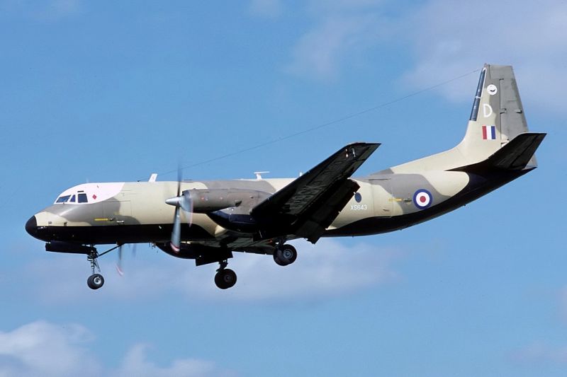
The Andover C.1 was flown for the first time on 9 July 1965 and the first four examples were flown to RAF Boscombe Down for acceptance trials that year. The full contract of 31 aircraft were delivered to squadrons in Transport Command. These were No. 46 Squadron RAF at RAF Abingdon and later RAF Thorney Island, No. 52 Squadron RAF at RAF Seletar (Far East) and No. 84 Squadron RAF at RAF Sharjah (Middle East).
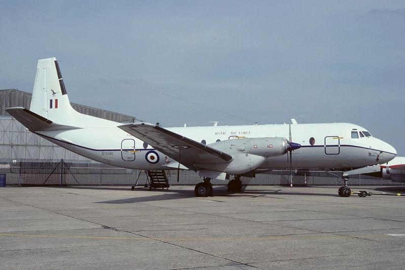
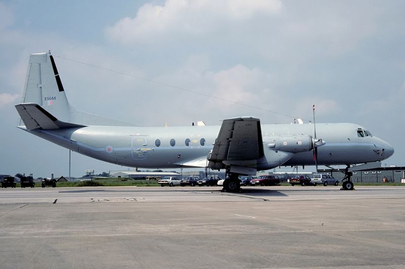
Three of the RAF Andovers continued to fly into the second decade of the 21st century, a C.1 with the Empire Test Pilots' School and one C.1 with the Heavy Aircraft Test Squadron of the Joint Test and Evaluation Group. The remaining aircraft was a modified C.1 converted for photo-reconnaissance, the Andover C.1(PR), serial number XS596; the UK-named aircraft under the Treaty on Open Skies; all three were based at RAF Boscombe Down.
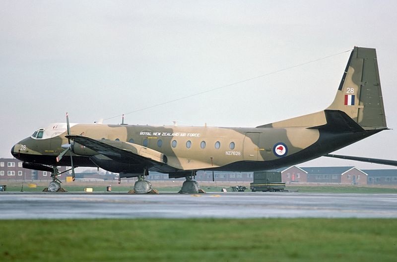
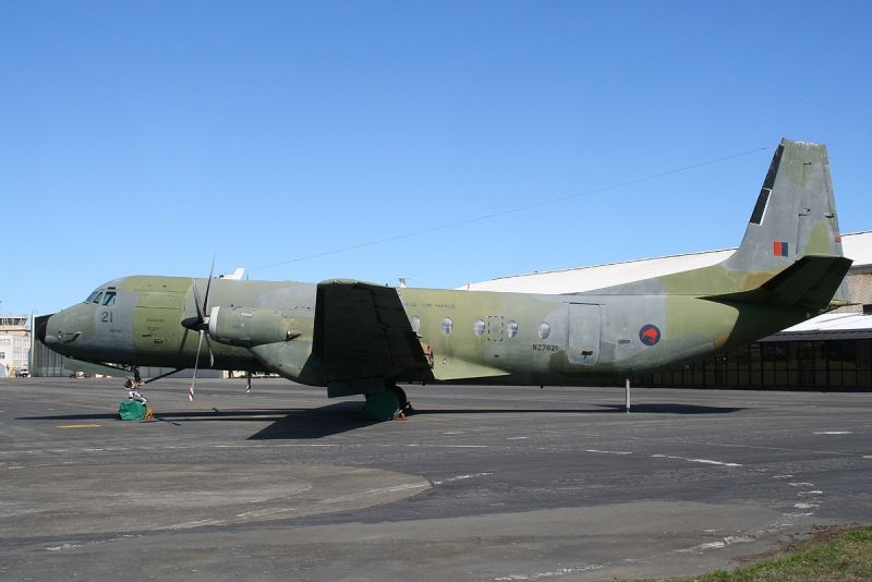
The Royal New Zealand Air Force operated ten aircraft from 1976, acquired from the RAF while still relatively new. These saw service with UN missions to Somalia and on the Iran-Iraq border and in disaster-relief work in the Pacific. The type was retired from service in 1998. The main difficulty with the Andover's service in New Zealand was its limited range—1,000 nmi (1,900 km) of Pacific Ocean separates New Zealand from its nearest neighbours.
- Andover C.1 - First production series for RAF, 31 aircraft built.
- Andover C.1(PR) - Two C1 aircraft was converted for Photographic Reconnaissance duties.
- Andover CC.2 - Not a variant of the cargo/transport Andover but a VIP transport version of the HS 748.
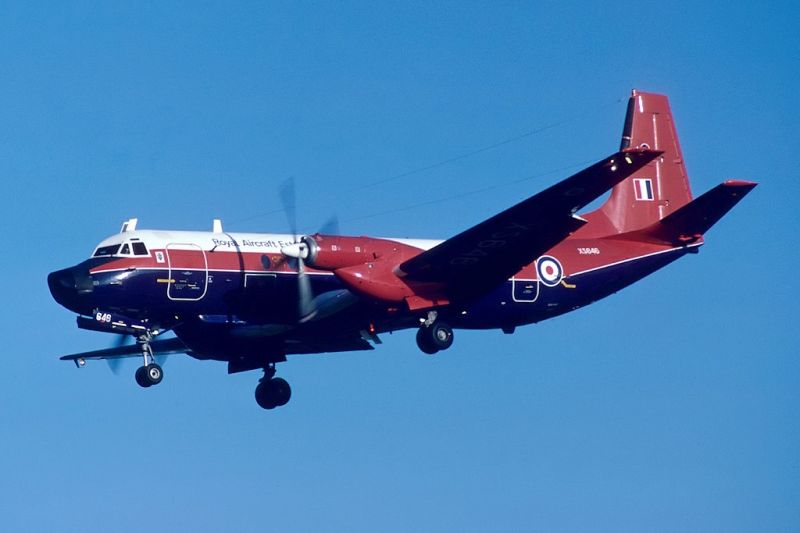
- Andover E.3 / E.3A -Seven C.1 aircraft were converted for radio and airport nav aid calibration. Four aircraft were equipped with an inertial referenced flight inspection system (IRFIS) and were designated E3. The other three aircraft didn't have this equipment installed, and were designated E3A.
One Man Model
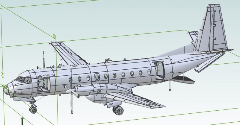
One Man Model is a small, one-man-band, based in Miyaga, Japan. The man behind it, Toshihiko Shimizu, is a very talented 3D Modeller who creates the designs in a 3D Modelling package on computer and then prints them for sale using FDM printers. (Fused Deposition Modeling). So far he's produced aircraft 'kits' in 1:72 and 1:48, but this is his first foray into 1:32 and Large Scale Planes.
So, who wants a 1:32 Andover?
Very occasionally you log on to the Interweb and spot something that immediatedly shouts 'what the...' Well, this was one of those moments. And it proceeded to create a 'disturbance in the force' - or at least my model building plans.
Forum member Anthony Galbraith had spotted that Toshihiko, of 'One Man Model', was drawing up the Hawker Siddeley HS780 Andover C.Mk 1 with a view to 3D printing in 1:72 and 1:48 scales. Anthony asked if this could be printed in 1:32 and the intial answer was a no. However, a few weeks later the answer came back as a yes - and Anthony posted on the LSP forums asking if anyone else would be interested in a 1:32 print of the Andover. Two immediate positive responses - and a slightly delayed yes from me - subsequently followed up by a fifth - and the project was on!
I'll be posting 'in-progress' photos of my build on the forums here.
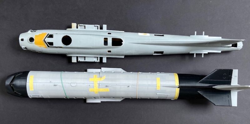
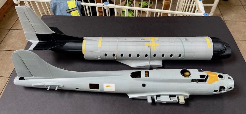
Oh, and beware, it's a fair size - here are the fuselage parts, taped together, compared to HK Models 1:32 B-17:
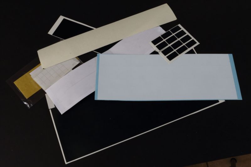
Parts
I considered a few options for going through the kit components, but given the unusual nature of it I thought I'd just post images of what's included, with the caveat that I've upped the contrast to show the details/shapes better, but this also makes the surface finish look worse than it actually is...
The FDM print process leaves a surface texture on pretty well everything that will need sanding with wet and dry papers before assembly. However, an initial 5 minute prep on the surface of a spare outer wing yealded good results, so this may take less time than I had envisaged.
All parts are printed using ABS (Acrylonitrile Butadiene Styrene) plastic - so you'll need bonding agents that work with this plastic type.
Many of the parts may prove to be un-useable in the final build, but anyone that's ever scratch built will know that having the basic shapes and dimensions to work from saves an awful lot of time and I'm confident that, where components don't pass muster, they will form excellent patterns for scratchbuilding alternatives.
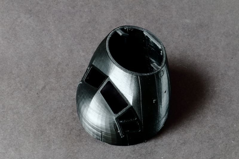
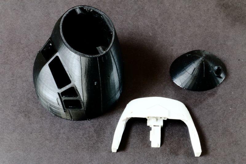
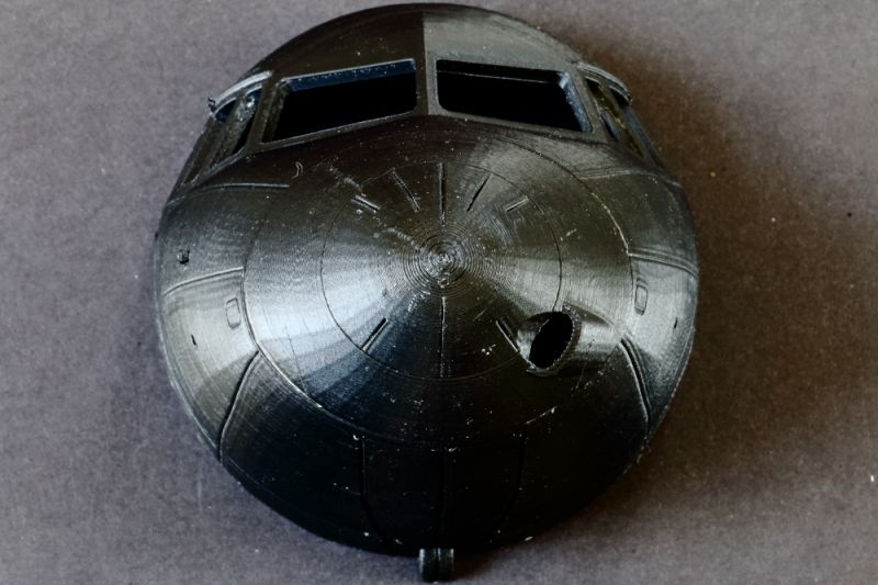
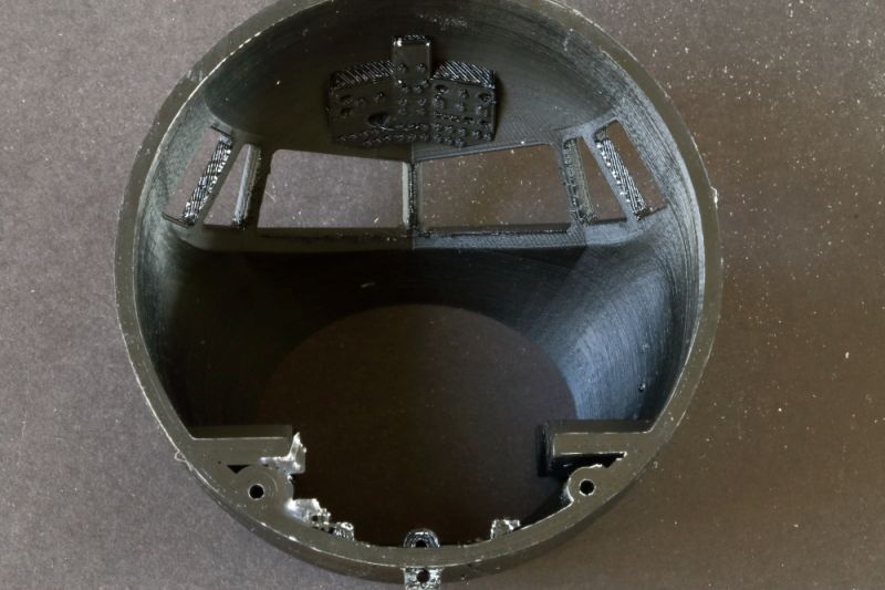
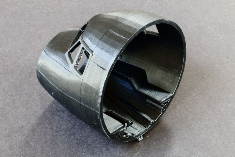
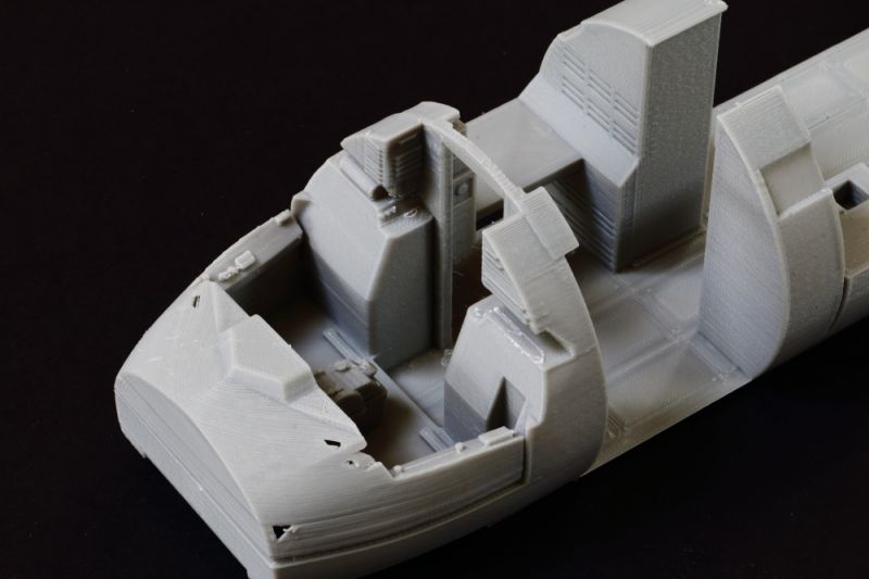
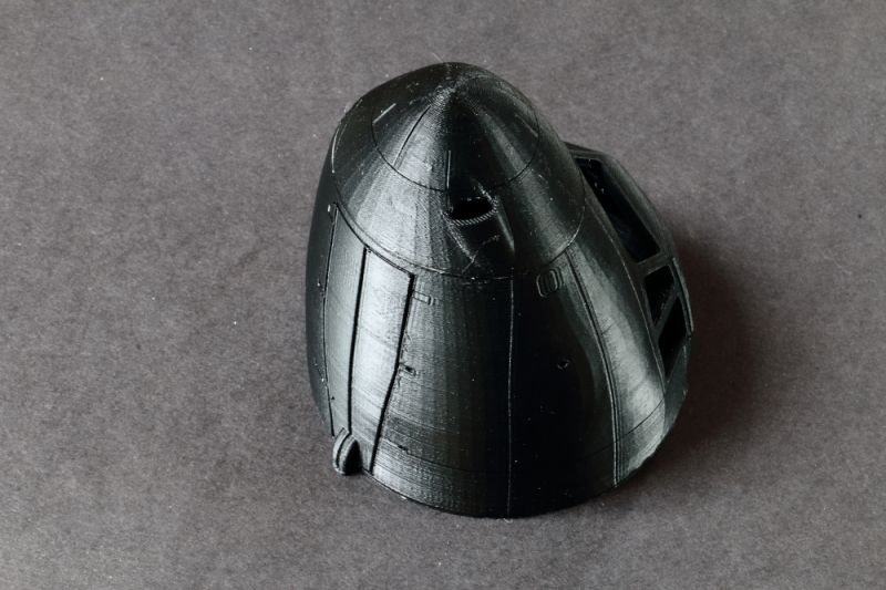
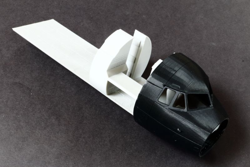
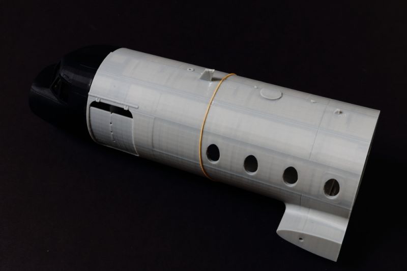
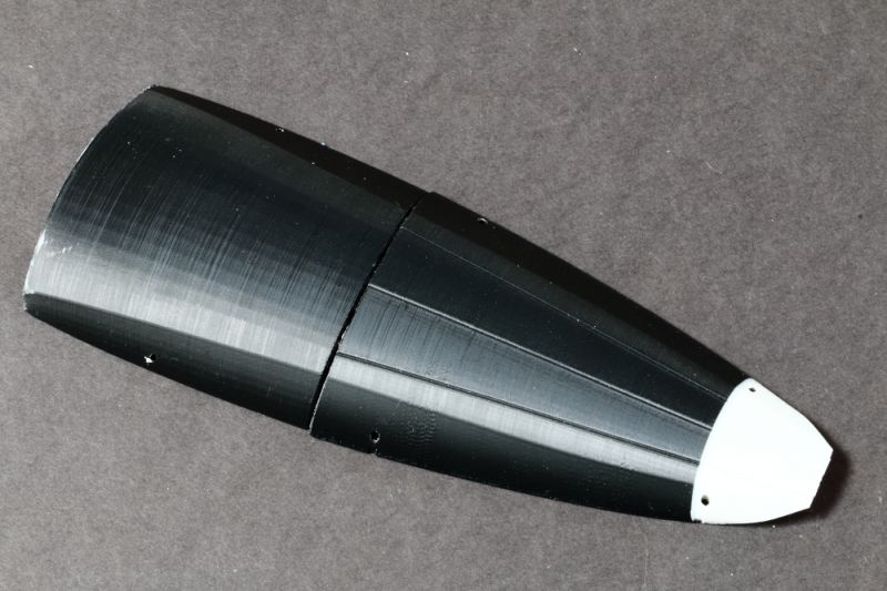
Nose
Not often you see an airliner type nose in 1:32!
Shapes look pretty good - although the cross section where the nose cap fits is a little too oval/too fat in plan view. I think there's enough wall thickness in the plastic to sand the worst of this out and re-profile. The 'eyebrow' windows above the side windows are printed solid - so I'll open those up and glaze accordingly. The roof instrument panel is printed in situ. The kit includes digitally cut clear sections to glaze this area with.
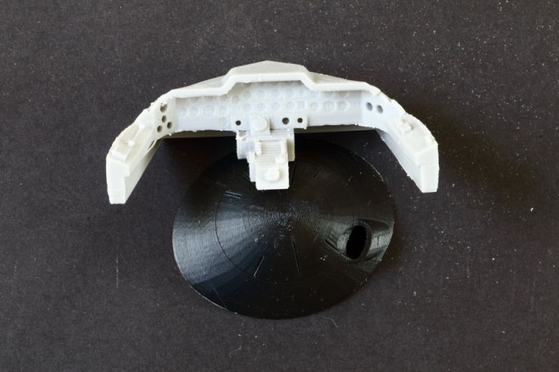
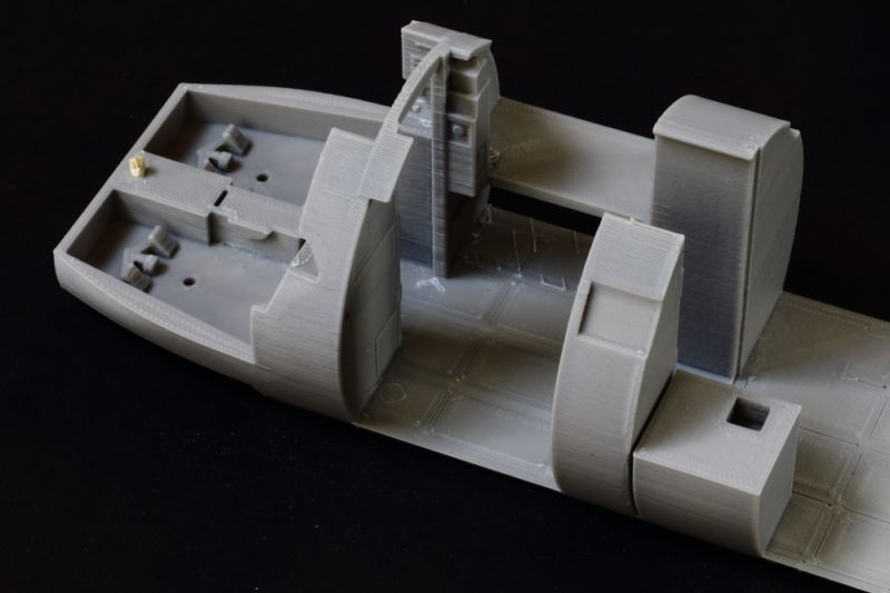
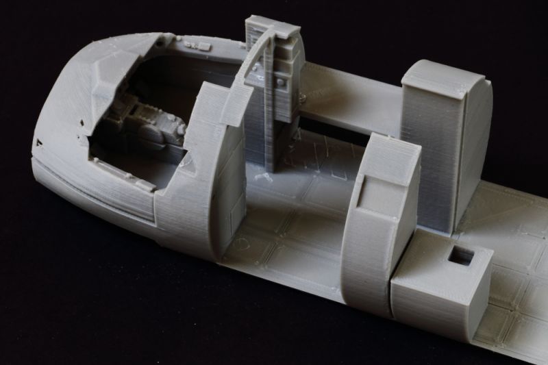
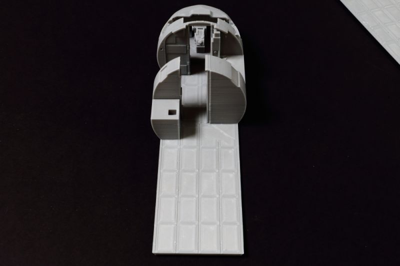
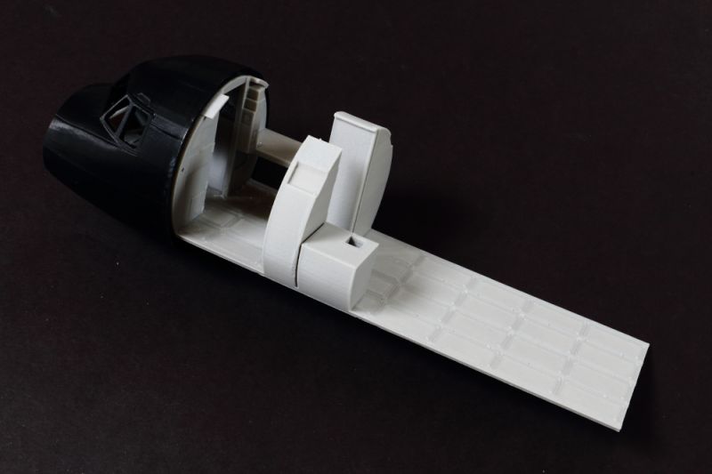
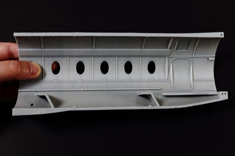
Full Interior!
Yup - it's pretty well all there and, although it will need surfaces cleaning up and additional detailing added, this will give the builder a huge head start. As part of the design process we were able to supply interior details and photographs - and Toshihiko has done an amazing job of incorporating as much as he could.
The parts provided even include the toilet!
Remember - with an open tail ramp and side doors - you'll be able to see an awful lot of the interior!
My plan is to prep and assemble the middle fuselage 'tube' section and build the interior section separately, then mate to the nose and tail sections when they are ready. The interior just slides in and sits on printed 'ledges' in the fuselage sections - so there will be a lot of bonded surface and resultant strength.
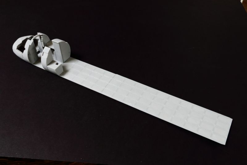
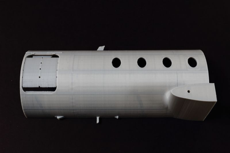
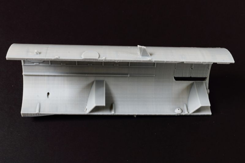
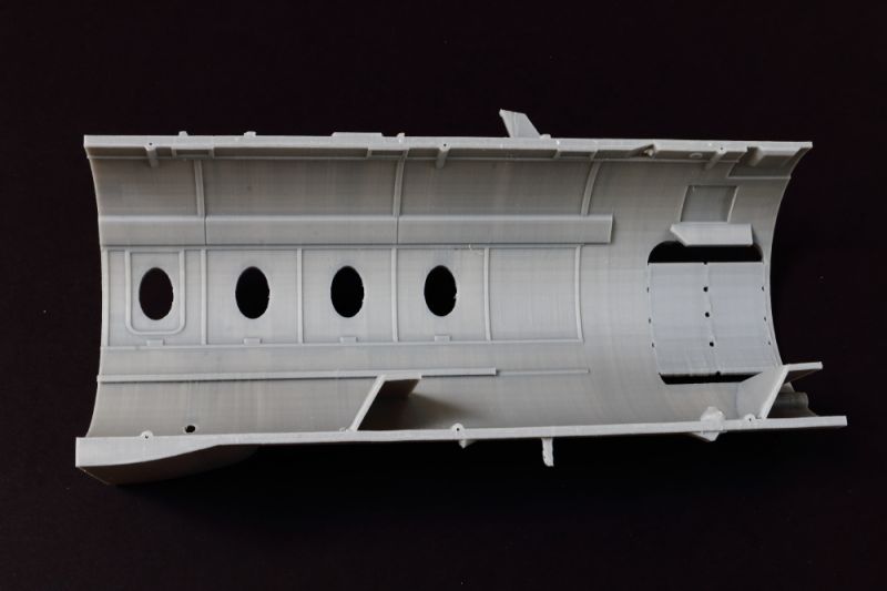
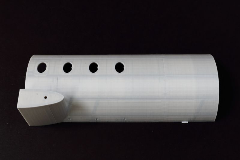
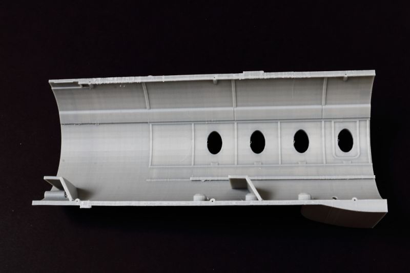
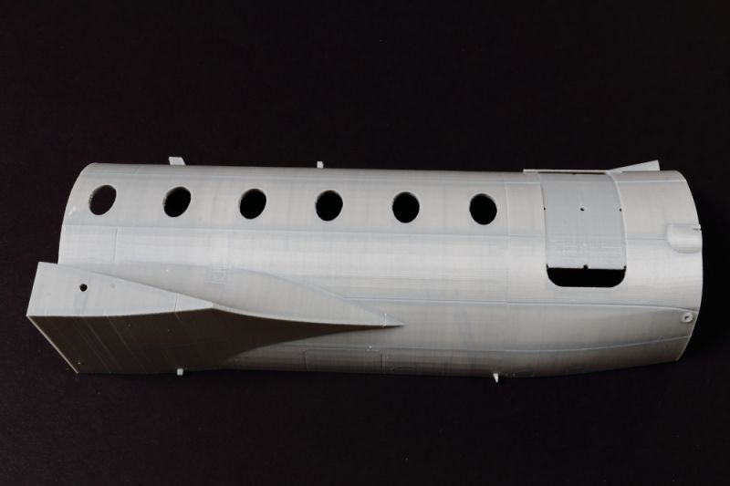
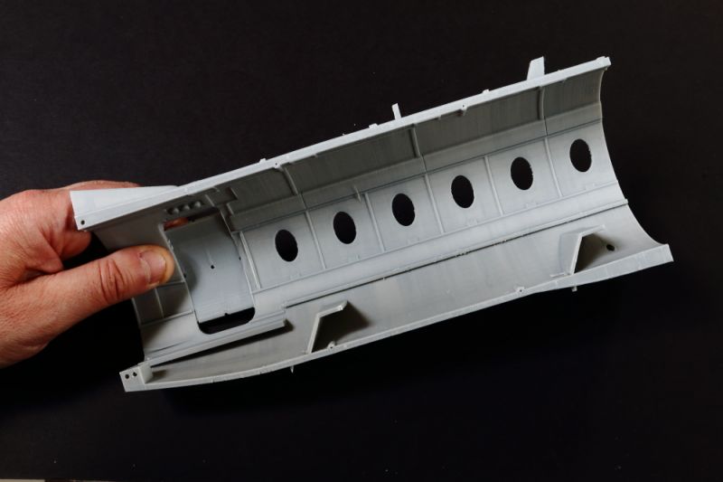
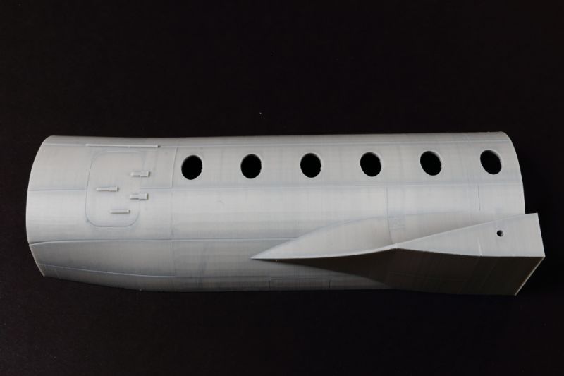
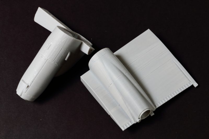
Fuselage Shells
These are impressive chunks of ABS plastic, split fore and aft to fit in the printer, and slightly off centre to provide an internal join along the edge of details, minimising clean-up required after assembly.
Both port side doors are designed to be opened: the openings in the printed parts are partially filled to provide support during the print process, but the areas are clearly deliniated to facilitate easy removal.
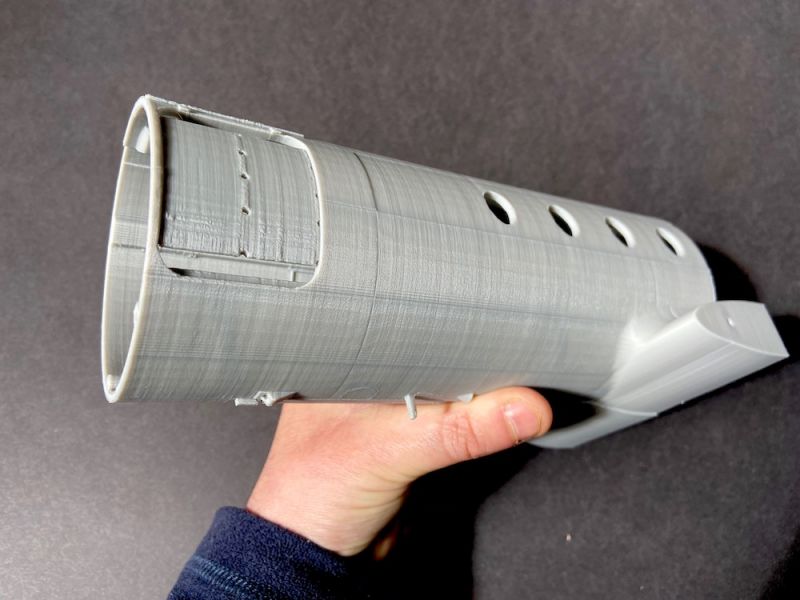
I'll let the photo's 'talk':
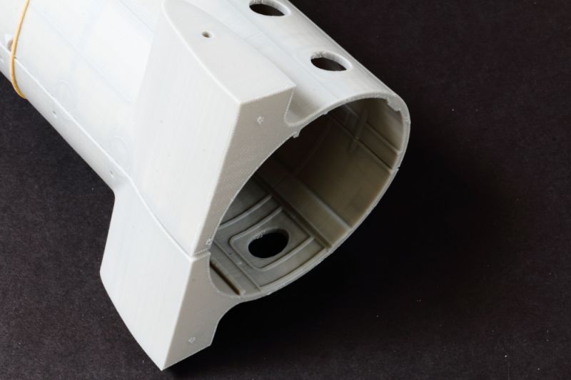
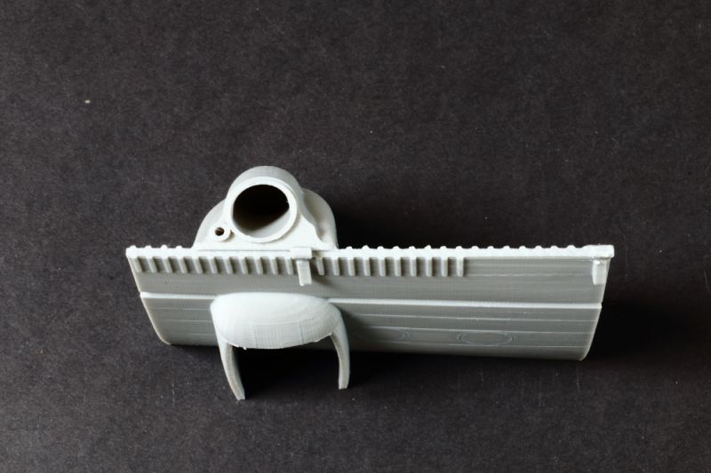
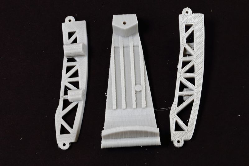
Tail Section
This is impressive - with structural detail on the inside! Not sure how well this will clean up - but it will be an early area to look at in the build.
The trailing edges are a little thick and will need thinning, but that's a function of the print process and to be expected.
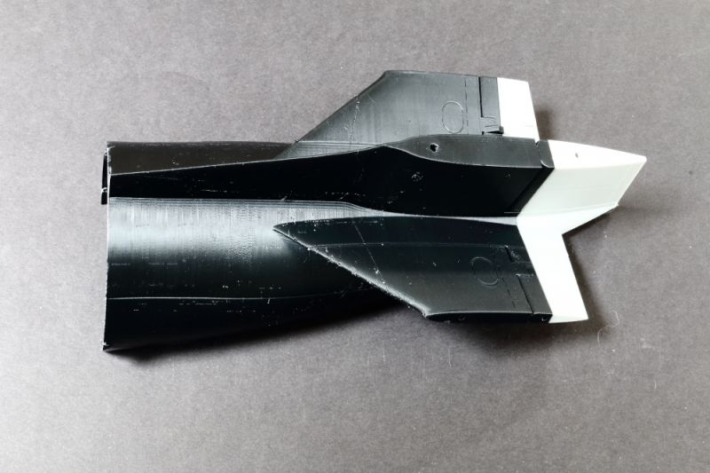
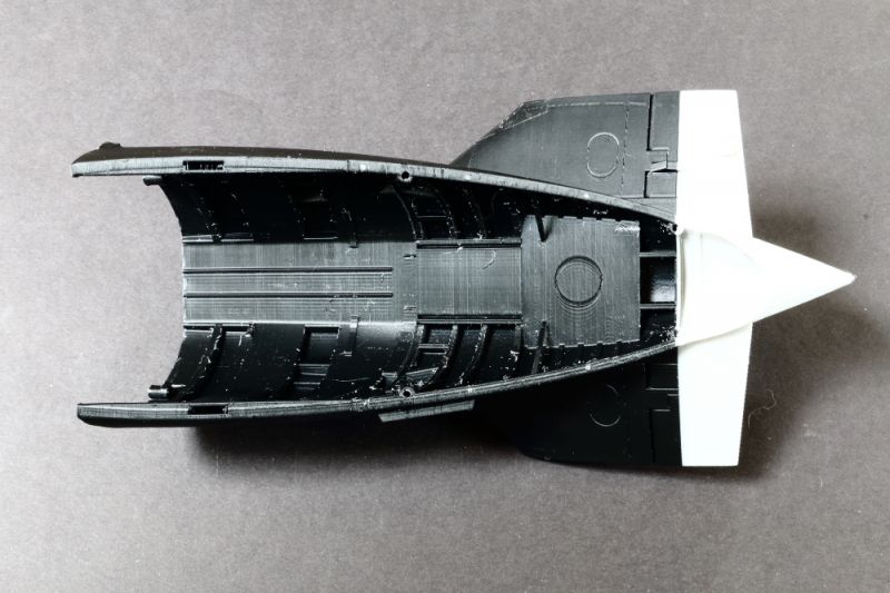
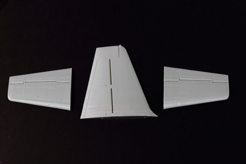
The way the tailplanes join the fuselage isn't quite correct, the sections inboard of the elevators should be horizontal - as printed they follow the dihedral of the rest of the tailplane. I'm thinking through a fix now but on the look out for any photos/drawings detailing the upper-surface tailpane root area - along with the vortex generators added ahead of the elevators (not included in the kit)...
IMPORTANT UPDATE: The 3D Model has been updated to vastly improve this area.
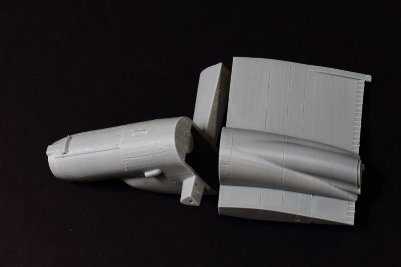
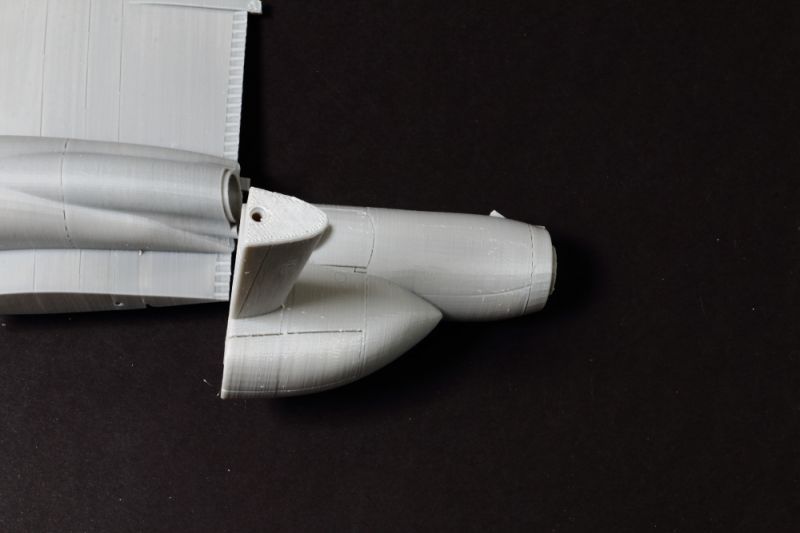
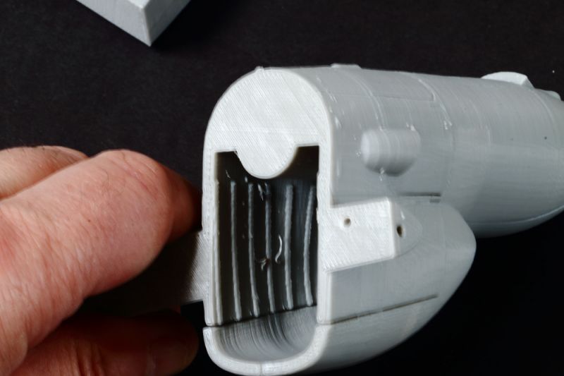
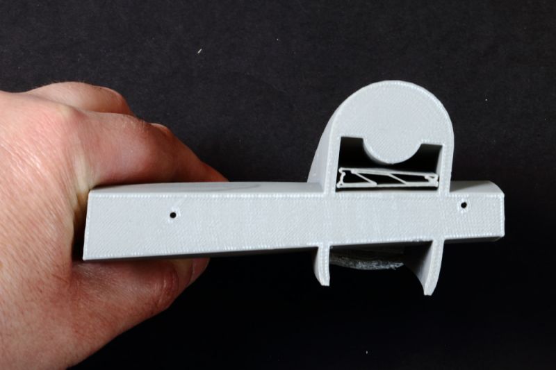
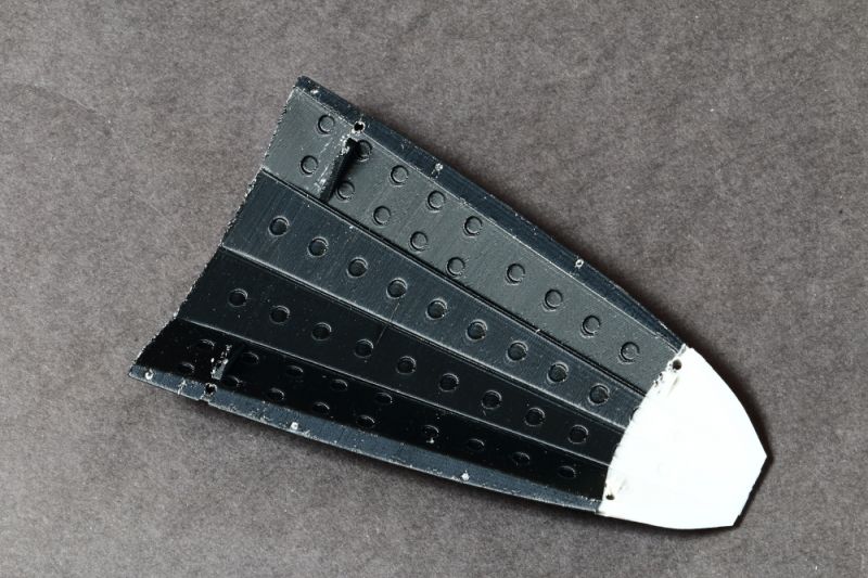
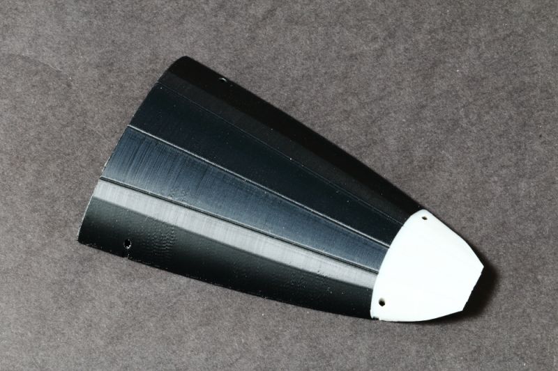
Engines and Inner Wings
These are quite chunky and will need finessing, but the basic shapes are there. The engine fronts on those Rolls Royce Darts aren't too good and I'll probably replace those. Some shape improvements could be made and the trailing edges thinned.
The gear bays are hollowed out and will provide a good space in which to add detail.
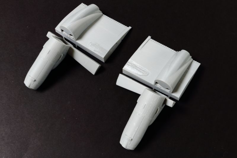
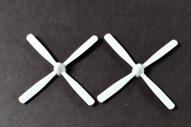
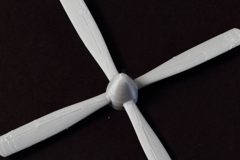
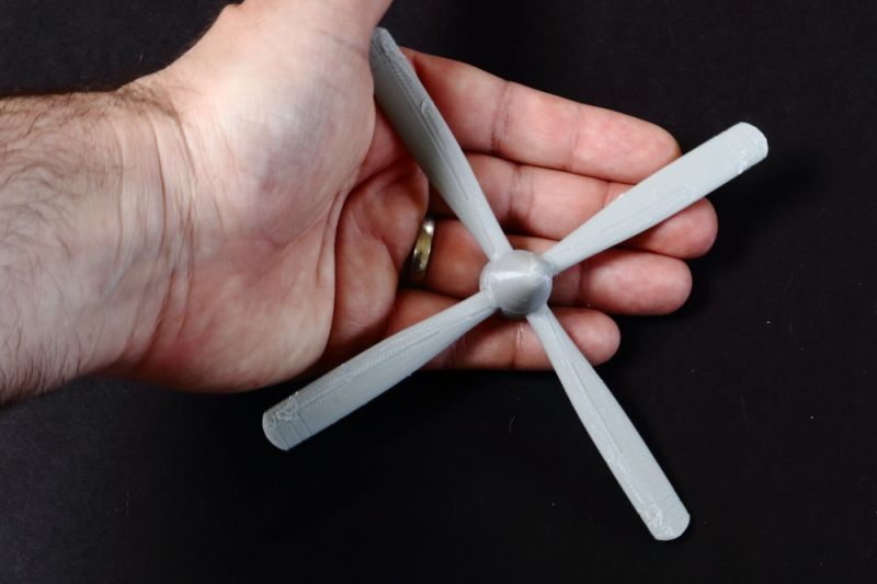
Propellers
I wasn't expecting these to print too well. I may try splitting from the spinner (slightly wrong shape) and sanding to see what the end result is going to be, but strongly suspect I will replace these.
They're not small!
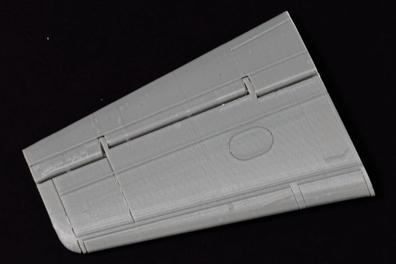
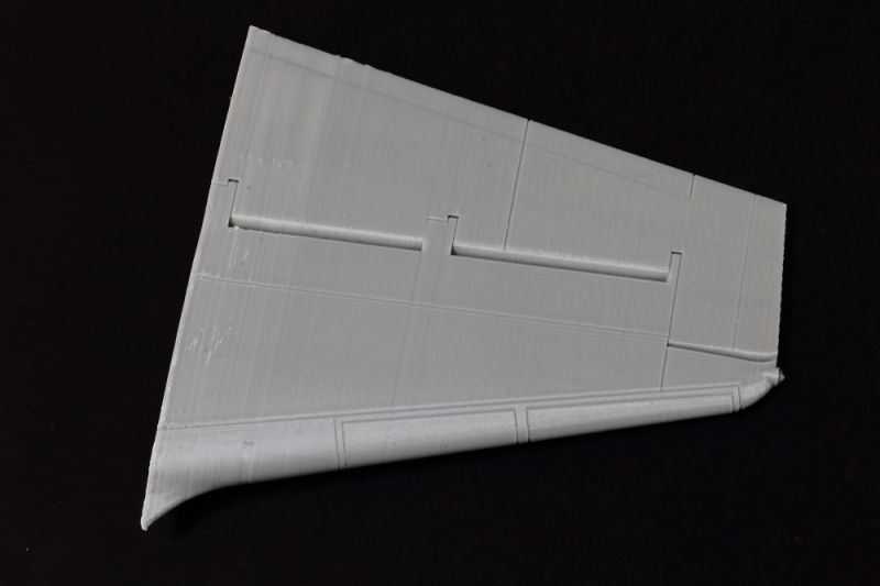
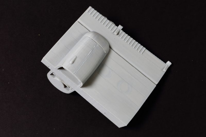
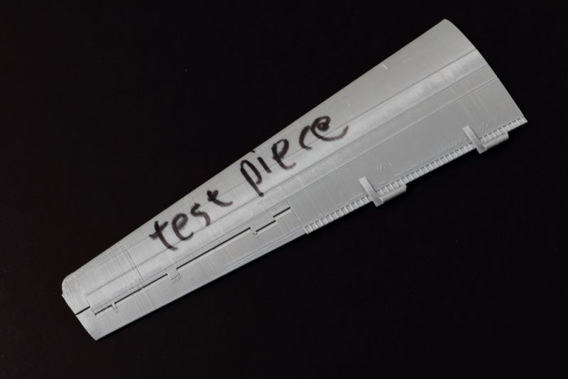
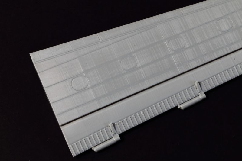
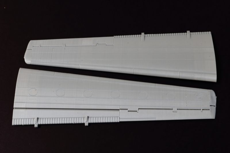
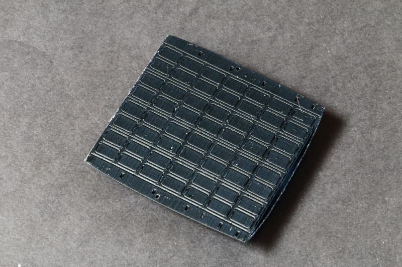
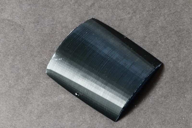
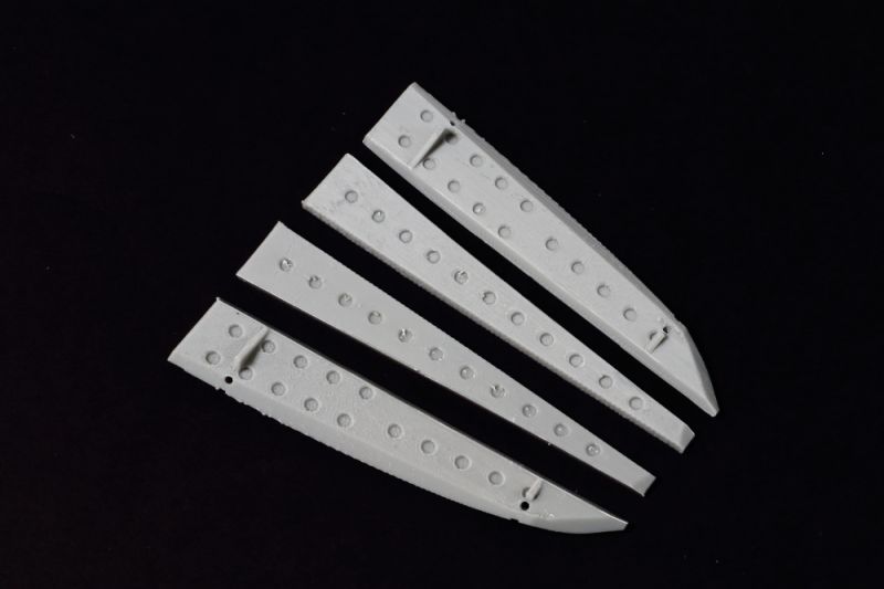
Wings
Great planks they are, but nice, light ones at that!
They are printed hollow and it looks like it will be a straightforward process to split off the ailerons to aid with thinning the trailing edges.
The thinning regime will also need applying to the flaps - and the stiffeners are portrayed as rectangular (in cross section) blocks where they should be triangular - so all of that can go during the thinning process...
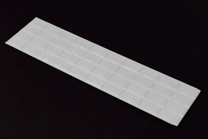
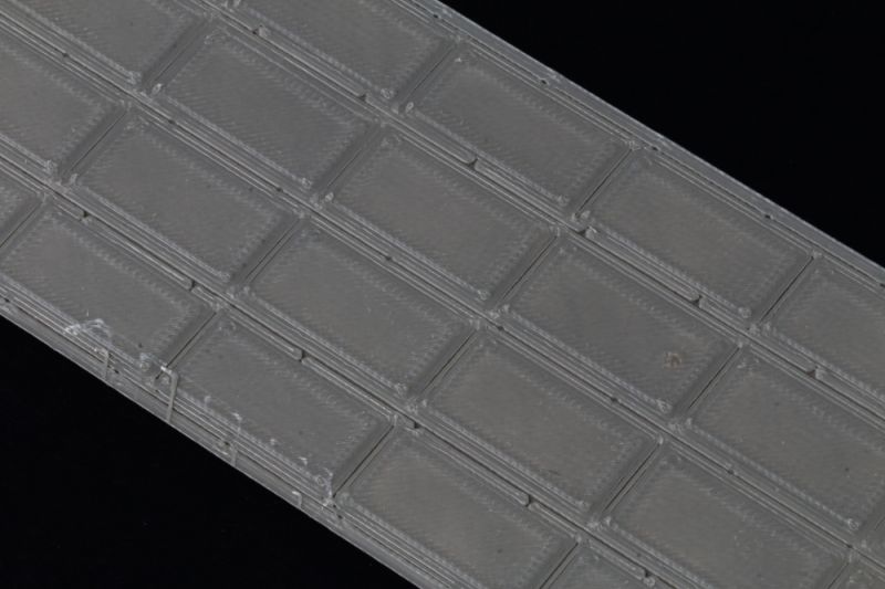
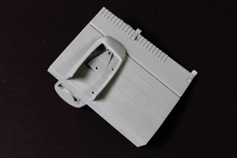
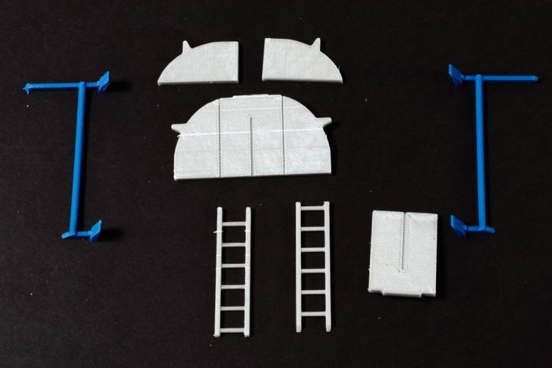
Rear Loading Ramp and Doors
Both open and closed options are provided - and should provide an excellent basis for further work.
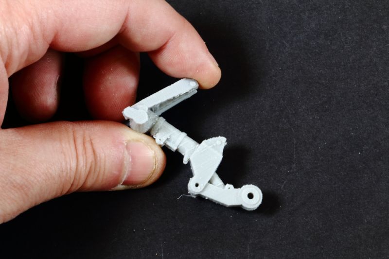
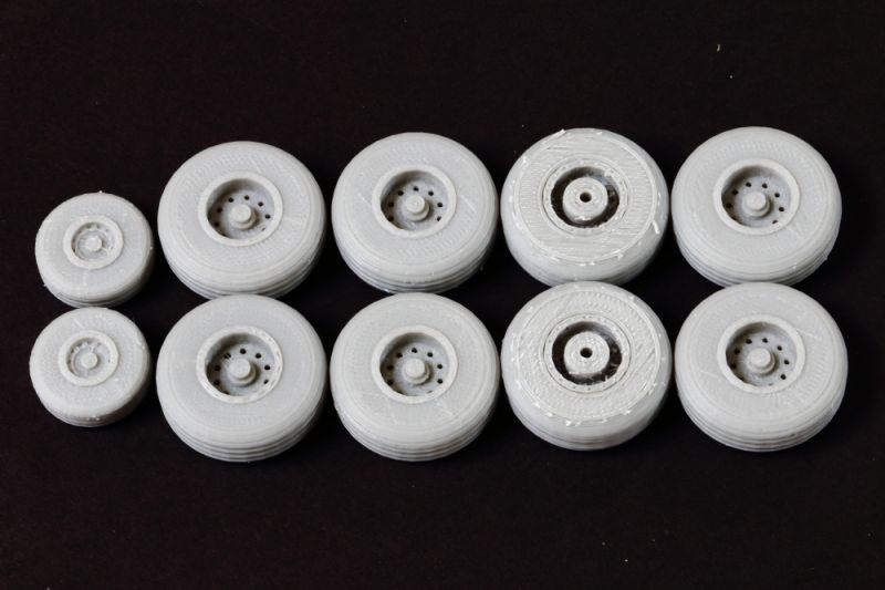
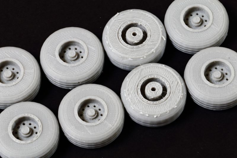
Undercarriage
Both standard and kneeling positions of undercarriage leg are provided - and enough wheels for both options, so you could assemble and later swap over on the model as your mood takes you.
Legs are probably a good base for further detailing and the wheels are better than I expected!
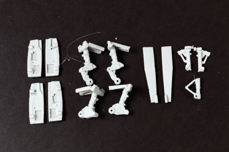
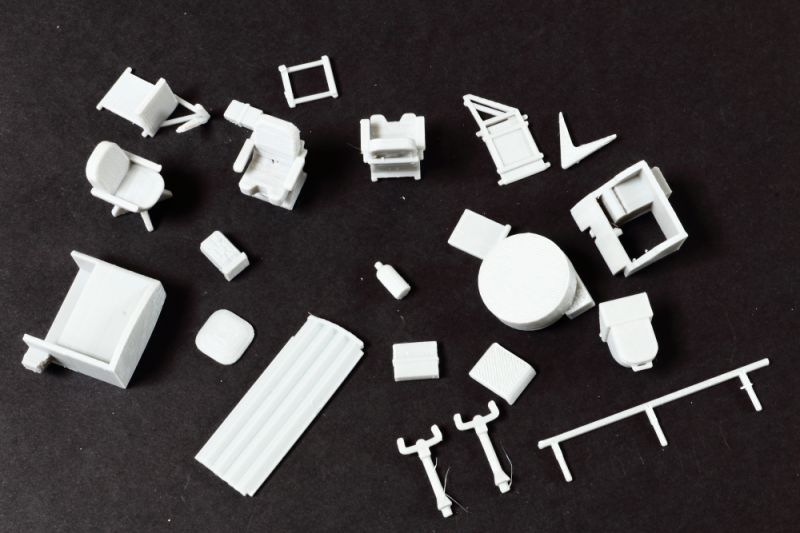
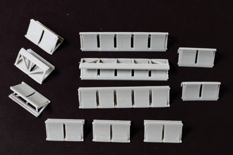
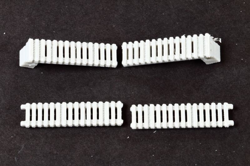
Miscellaneous Parts
Quite a few of them - from para seats, to ramps and further interior details. The parts even include the aircraft toilet!
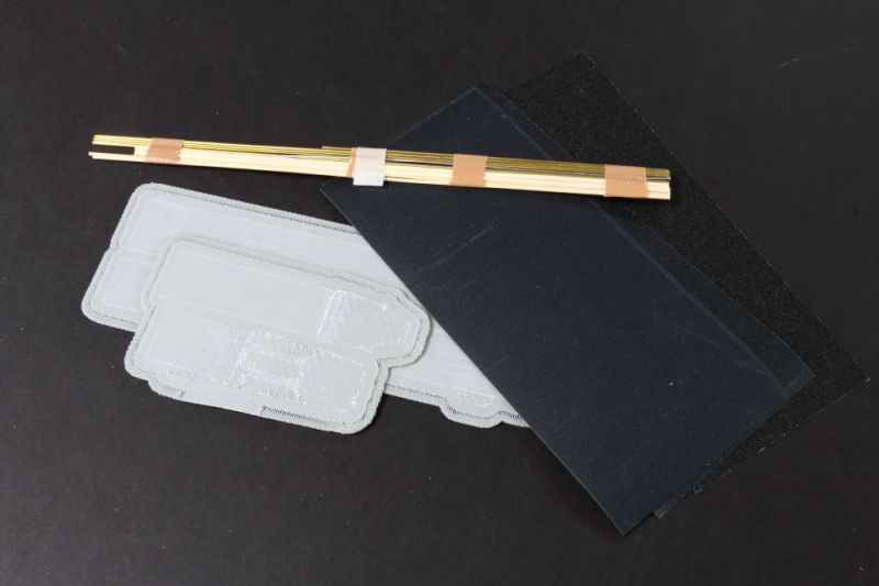
Additional Items
Toshihiko includes some additional items with his kits - 3D Printed ABS 'plate', Bamboo and Brass for joints and a number of digitally cut parts (instrument panels), windows in clear material and 'markings' that can be used for paint stencils.
Initial Thoughts/Findings
All surfaces will need smoothing using sanding sticks and wet and dry paper - all to be expected given this is an FDM type print - but less than I expected.
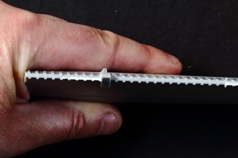
Trailing edges are quite thick - 2.29mm on sections between the flap stiffeners - again, to be expected given the process.
Flap stiffeners are overscale - and are a rectangular cross section when they should be triangular - straightforward fix.
Nose appears to be too fat in width were cap fits - resulting in too oval a cross section - I *think* there's enough meat on the plastic to re-profile - but may be need to fill inside with Milliput first. Anyway - fixable - and, actually - doesn't look too bad at all with the nose cap in place...
Tailplane to rear fuselage interface is wrong - the sections inboard of the elevators should be horizontal - as printed they follow the dihedral of the rest of the tailplane. This tailplane/fuselage interface area is actually a complex shape. I think I may have to resort to hacking the tailplanes off completely and re-doing. This will take the most work to fix.
IMPORTANT UPDATE: The 3D Model has been updated to vastly improve this area.
Front section of cowling - where the access doors are - look out in side profile - too much of a curve on underside. Should be a relatively easy fix - especially if adding engines!
Outboard flap actuators in wrong position - easy fix when thinning wing anyway...
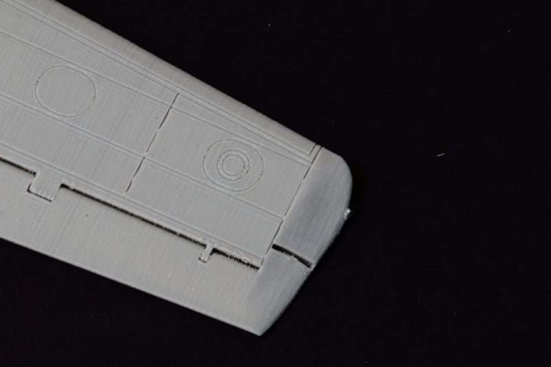
Wing tips will need filling and re-profiling - and slight change in plan where it curves around outside edge of aileron. Easy fix.
Conclusion
I was expecting a really basic canvas - so what arrived in the box from Japan exceeded my expectations.
It appears that it will, indeed, be a great canvas - and a whole lot quicker and easier than a traditional vacuum formed kit.
Given the structures as printed - and the light weight of the parts - I suspect it will be a faster build than a complete resin kit too.
But you'll have to approach it with the right mindset: it's a basic canvas where most of the shapes are ready to go, subject to clean-up. It will need a lot of work and some scratchbuilding to produce a built model to a high standard, but to me that's part of the fun. And, where else are you going to find a 1:32 Andover?
Recommended!
Availability
A search for onemanmodel on Ebay should result in a list of of currently available prints, but you can also find him on Facebook and via email.
Credits
My thanks to forum stalwart Anthony Galbraith, in New Zealand, for thinking way outside the box and asking if it could be done, and then sharing the opportunity with others. And thank you to Toshihiko for doing the CAD design work and agreeing to print in 1:32 - who'd have thought we'd ever see an Andover in 1:32 scale!
Review courtesy of my wallet.
Iain
© Iain Ogilvie 2020
This review was published on Sunday, May 17 2020; Last modified on Wednesday, September 02 2020