
Cyber-Hobby/DML | Cyber-Hobby/DML Bf 109E-4
Reviewed by Ray Peterson
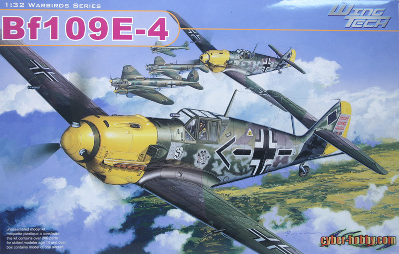
The latest in the 1/32nd Warbirds Series "Wing Tech" line by the Cyber-hobby/DML group is kit #3204, the Messerschmitt Bf109E-4. An interesting choice, given the 109Es already produced by Eduard and Trumpeter; and Hasegawa and Matchbox before them. My plan is to review the DML kit on its own, then follow up with a comparison review of all 5 manufacturer´s kits.
The kit comes in an attractive, sturdy box, with a painting of Galland´s 109E-4/N from the Battle of Britain era on the boxtop. It contains:
- 6 newly tooled sprues in grey plastic
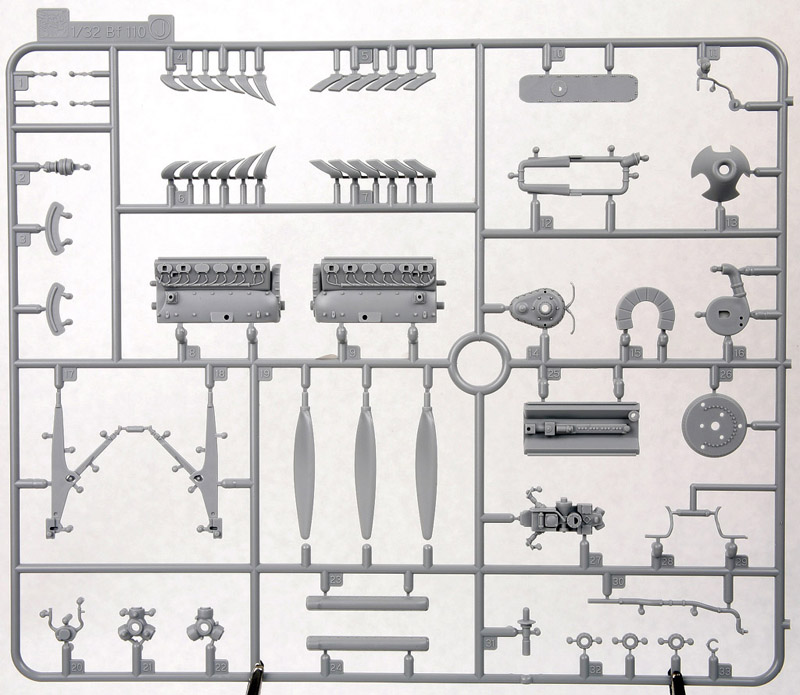
- 1 sprue from the Bf110 kit (the engine)
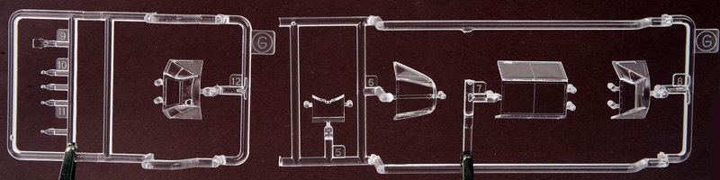
- 1 sprue in two parts of clear plastic
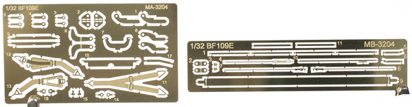
- 2 small PE frets
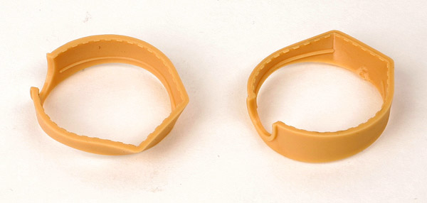
- 2 parts in "DS" (Dragon Styrene), a flexible plastic glueable with standard cements
- 2 small sheets of decals
- 10 page accordion-folded Instruction Sheet
Sprue and Part Pics
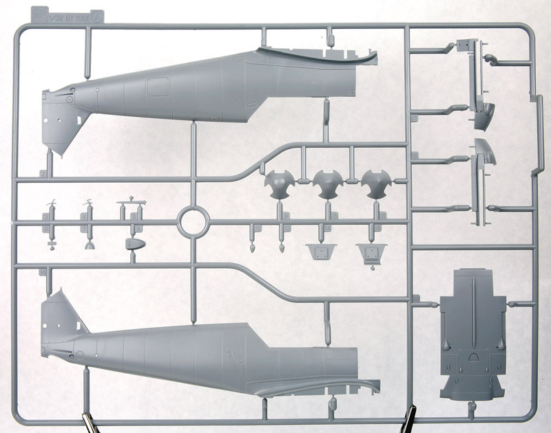
Overall the kit seems accurate in outline and major details. I mainly used the drawings from the Model Art and Aero Detail books on the Bf 109E-4; both books use the same drawings. My main reason is the drawings are to scale and are dimensioned, which match listed numbers, especially the 8800mm and 9900mm overall length and wingspan. With these drawings printed out to scale, the DML kit matches very well, with everything matching up within a single mm in plan and profile. Maybe these are some of the drawings they used to design the kit? I am still trying to determine how accurate the drawings are...
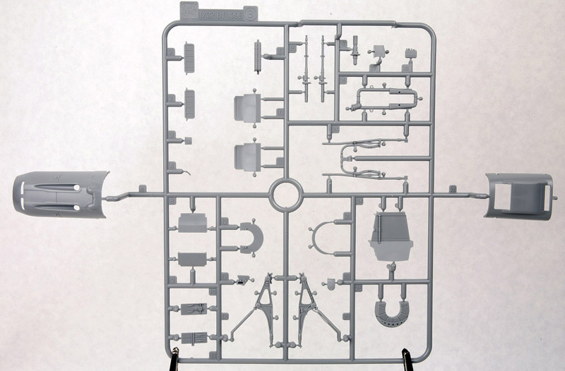
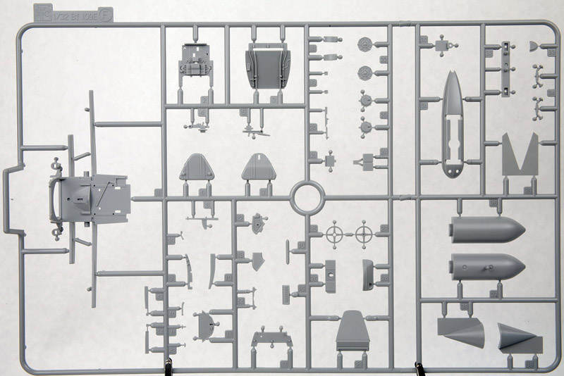
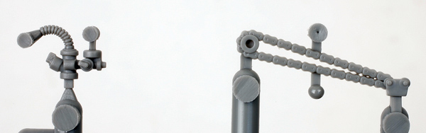
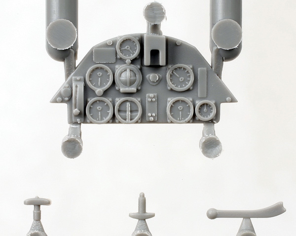
The kit construction begins with the first four steps as usual with the cockpit, with the addition of the MG17 gun tray. It is well detailed, especially considering there is very little PE used. A total of about 44 parts make up this assembly. The detail is quite good, although some parts would be more in scale if they were in PE. A first is the separately molded chains for the trim wheels, very nicely done if a little thick. The oxygen regulator is also in the picture.
The instrument panel has sharply raised detail. Although some small placards are provided as decals, you are expected to paint the dials which some may not like. Decals might have a hard time going over the detail, though. Some of the provided handles are shown in the picture, too. Please note part F-30 is the bomb selector panel that I believe should only be in the E-4/B fighter bomber cockpit. It is also a mirror image of the real one! So if you are doing a standard E-4 or E-4/N, don´t use it.
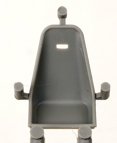
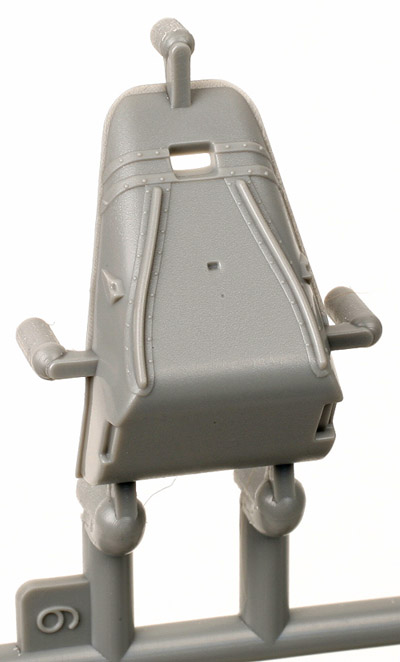
The seat appears a little narrow at the top, although I am looking for more info on the early 109 seat. The only good photos I have seen are in the Modellers Datafile book, "The Messerschmitt Bf 109: A Comprehensive Guide for the Modeler; Part 1: Prototype to ´E´ Variants." The pictures on page 128 make it appear the DML seat is really not that far off. The detail on the back side of the seat matches the pictures of the actual seat well, too. An additional part, F-14, adds to the detail as the prominent horizontal reinforcing member.
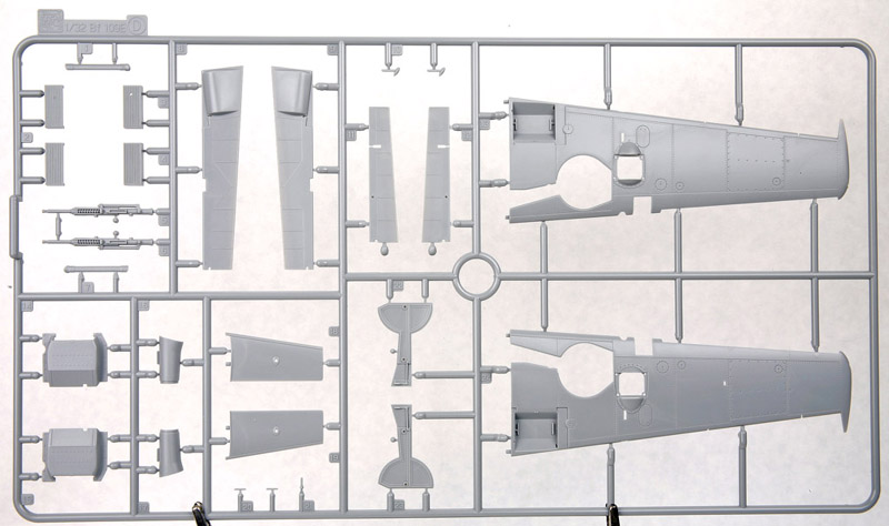
The cockpit construction finishes with it being trapped between the fuselage halves in step 4. DML has you build this kit similar to how Tamiya has you build the Spitfire IX: the power egg is built and added separately from the rest of the fuselage and wings. Note in step four the fuselage half already shows parts A-12 and A-13 in place. They are tear-drop shaped fairings that go over the wing spar connection bolts on the real aircraft. I assume DML decided to provide them separately to help the modeler with any joint filling, but no one apparently told the CAD operator drawing up the instructions!
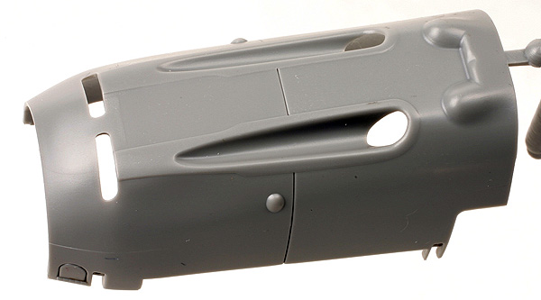
Steps 5 through 7 are for engine assembly. It is the same nicely detailed engine from the Bf110 kit, with new parts necessary for the single-seat 109. The whole power egg is very nicely done with petite detail, consisting of about 37 parts, not counting the propeller. Of course, more could be done especially regarding wiring. The chin oil cooler can be built with or without the center splitter. Check out the detail on the engine bearer, as well as the separate cover for under the nose:
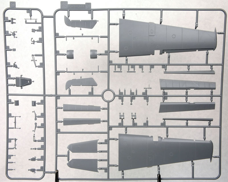
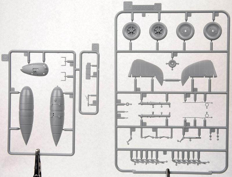
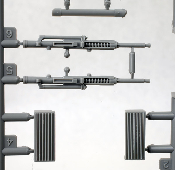
Next up, steps 8 through 14 is for the wings. All moving surfaces are separate, and PE hinges are provided that allow the surfaces to move. Unlike similar attempts by other manufactures, these hinges are meant to be in the same locations as on the real aircraft, and are about as close to scale as they can get, with some miniscule pins and PE parts. I suppose you could attachment points, too, where they can´t be seen if you are worried about them staying put. Detail on the wings is very good, including cannon and ammo drums for the MG FF´s in the wing and even tiny eyebolts for the wing tie-downs. The slats are separate, and appear to be the correct size. They are a little thick, though. A separate cover is also provided for the bulge over the ammo drums. The radiator faces and a brace for the tail plane are also shown in the picture.
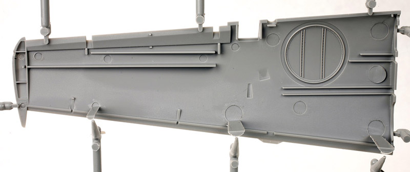
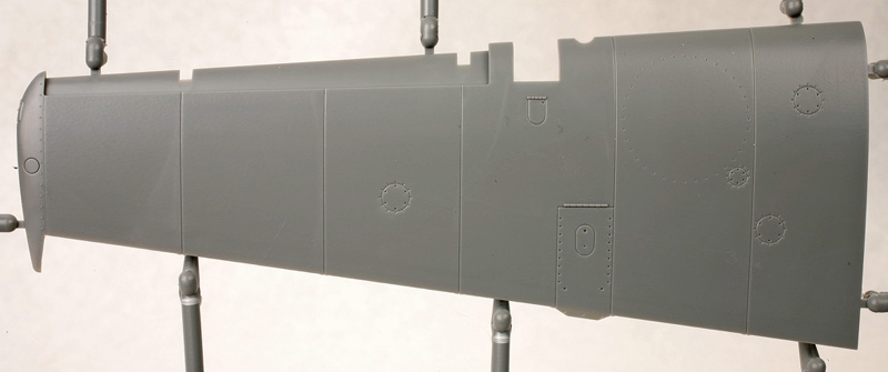
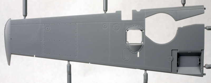
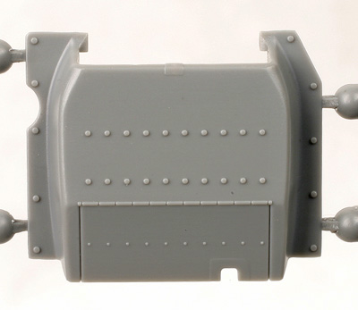
Flexible plastic is used for the canvas covers around the wheel wells. It should be easier to place than PE since it gives a bit. The interior framing in the wells is molded on the upper wing half. Also of mention is the way they designed the sprue attachment points. All gates are inside or on the glue surface of the wings, no burrs on the exposed face. Note only major fasteners are included; this kit does not have the full rivet treatment. There are a lot more fasteners provided on the lower wingsurfaces, though.
The radiators are made up of 5 parts, including separate radiator covers, although the rear flap is not a separate part. Don´t forget part D-20, the brace at the front of the radiator, it is not shown well in the instructions.
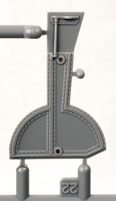
Steps 15 through 17 are for the tail plane and tail wheel. The tail wheel bay isn´t all that well detailed, though not much can be seen with the wheel in place. It is nice to see that the tail wheel is provided as a separate part sandwiched between the two tail forks, instead of a single part. The rudder is also hinged similarly to the other moveable surfaces, including 3 PE parts to make up the rudder control horns. It looks fiddly; care will be needed to keep from bending the long thin PE wires. You might want to replace those with small gage steel wire. You might even be able to make it work! One note: from drawings, it appears DML put the trim tabs on the elevators one panel too far to the outside. They should be at the 3rd panel from the rudder, not the 4th.
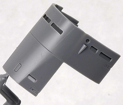
Steps 18 through 20 complete the model. The power egg is attached, and the cowls are added around it. Note the cowl fasteners are spindly little things on the lower cowl halves, don´t break them off! They fit over the half-filled slots on the upper cowl. Note also the gun cowl is one piece, a pretty nice piece of injection molding! Unfortunately, no rivet detail on the cowlings, just the fasteners.
The prop is assembled in this step, too. There are actually 4 types of spinners provided. Only two options are given in the kit, the standard spinner with the center opening and the blunt tipped spinner as used on Galland´s aircraft. However, two of the more pointed spinners are provided, one probably intended for a future E-1 kit, but the other could be used for some E-4´s if your references call for it.
The canopy is one of the last things added. Two versions of the windscreen are provided, the standard one and Galland´s special one with the telescope through it. There is also a separate armored glass section provided and marked not for use, but you may find some E-4´s call for it. Also two types of rear armor are provided, one with and one without the curved armor to help protect the back of the pilot´s head. PE parts are provided for the canopy stay.
Lastly, the option of a drop tank or bomb is provided along with the appropriate carrier, although I am not sure any of the decal options call for them? We are not given any clue whether they do or not. At least you have the option. The bomb looks a little big; according to my references only the SC250 could be carried, the 500 did not allow enough ground clearance. I haven´t found a good reference to tell me which bomb it is yet. Don´t forget, if you do build an E-4/B fighter bomber from the kit, you do need the bomb arming panel part F-30.
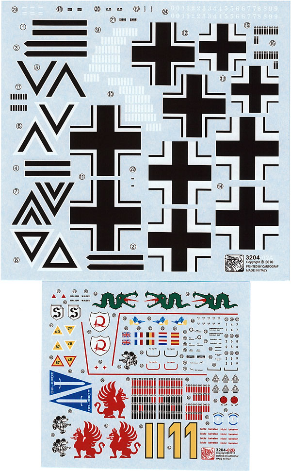
Five marking options are provided, including Oberst Galland´s E-4/N of JG 26; Hauptmann Rolf Pingel of I./JG 26; Hauptmann Gunther Lutzow of I./JG 26; Oberleutnant Gerhard Schopfel of 9./JG 26 and Major Helmut Wick of JG2, all 5 located in France in 1940. All appear fairly accurate, with good stencil data, including the correct C3 designator for Galland´s aircraft. They are printed by Cartograf and appear thin and in good register. They do have a flat coating, however, which I for one don´t favor.
In summary, a very nicely done kit. I only wish they had provided some fine rivet surface detail similar to the Eduard kit. But more on that with the 5-way comparison to follow! It is definitely a job well done, a nice follow up to the Bf 110!
Highly recommended
© Ray Peterson
This review was published on Saturday, July 02 2011; Last modified on Sunday, February 04 2018