
Rolls-Royce Merlin 23
Photos By Max Otten
Photos were taken at the RAF Museum, Hendon (London, England), in 2008.
This type of Merlin is still the single-stage supercharged engine but there are numerous detail differences with the earlier (Battle of Britain) Merlin III. As far as I recall the museum text states it is two-stage but that would be wrong; they probably meant two-speed as the two-stage superchargers only were from the Merlin 60 series onwards, with the prominent cubical unit at the top/back which houses the intercooler. Since most people have difficulty with Roman numbers larger than XX (20), the later marks were denoted with normal numbers. This type of Merlin is similar to that installed in Spitfire Marks V as well as Mosquitos. I used it as a reference for superdetailing and - a lot of - correcting the engine of the Trumpeter 1:24 Spitfire Floatplane. In the comments I will pay special attention to the difference with the Merlin III. The engine on display is positioned with its starboard side against a wall, so almost no photos from that side. Fortunately it is a side that did not change between the marks so one size fits all (look for other Merlin marks walkarounds).
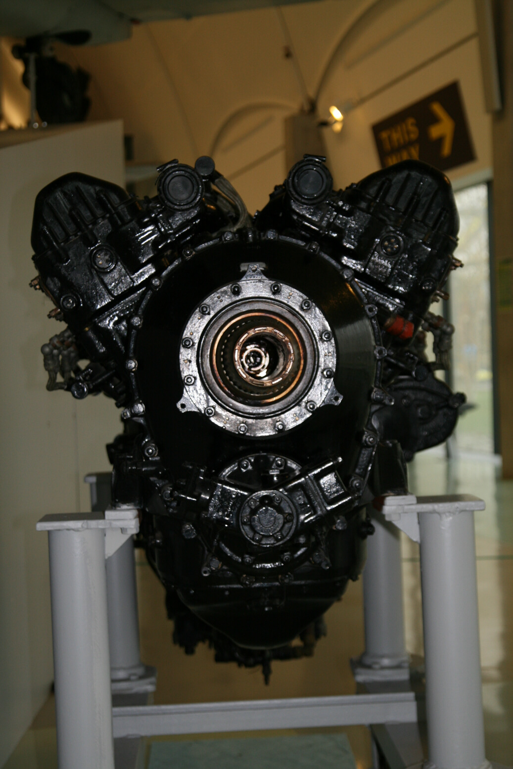
Photo 1 shows a front view of the engine. Note the tilt of the starboard and port cylinder banks, which is close to +/- 30° (far more than the Trumpeter engine with its +/- 15°, requiring a major correction). The (oval) front part is the air screw reduction gear. The two circular plates above it cover the outlets of the cooling system where it is connected to the (absent) coolant header tank.
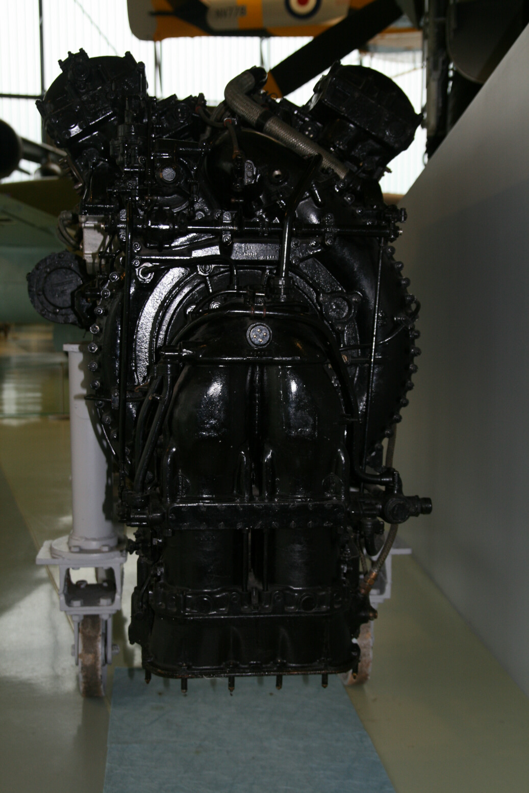
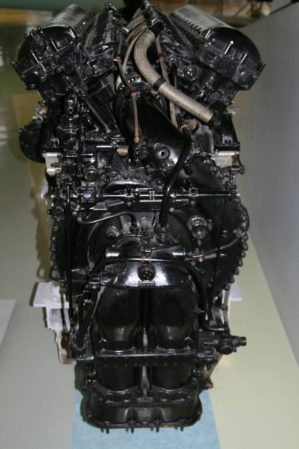
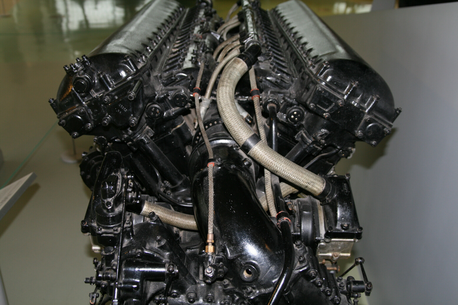
Photos 2 and 3 show the back of the engine. This is the place where there are numerous differences with the Merlin III. First of all, the ignition wiring for the inner spark plugs (on top of the engine) is asymmetrically laid out, in a single thick braided wire displaced towards the starboard side of the engine. The back side of the supercharger air intake is also quite different in the details. Another difference is in the carburettor, with the control rod from the engine control lay shaft displaced to the far starboard side. And finally, the compressor (absent on this engine) has far more cooling plates than the one on the Merlin III (see the Science Museum engine).
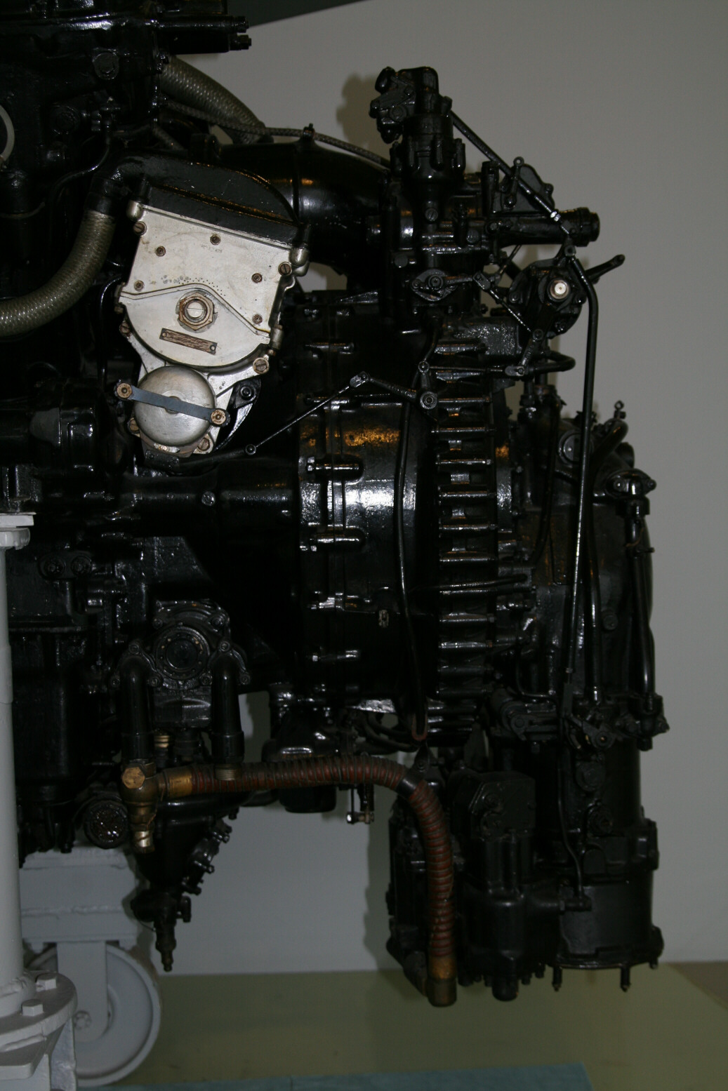
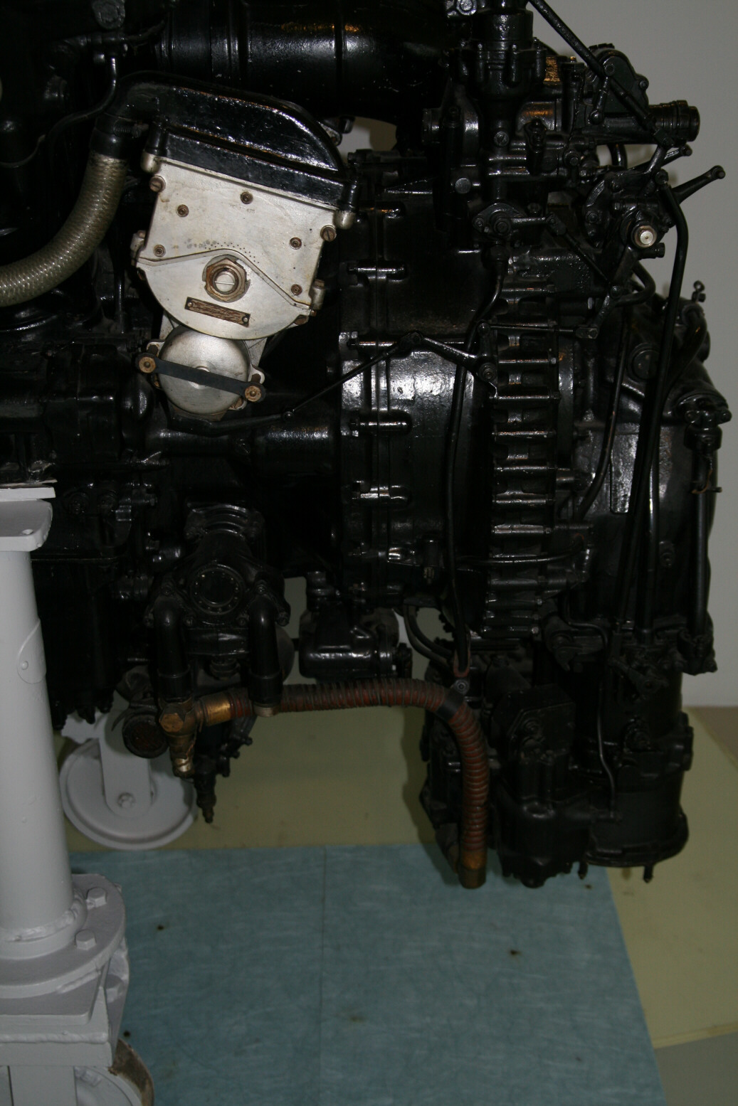
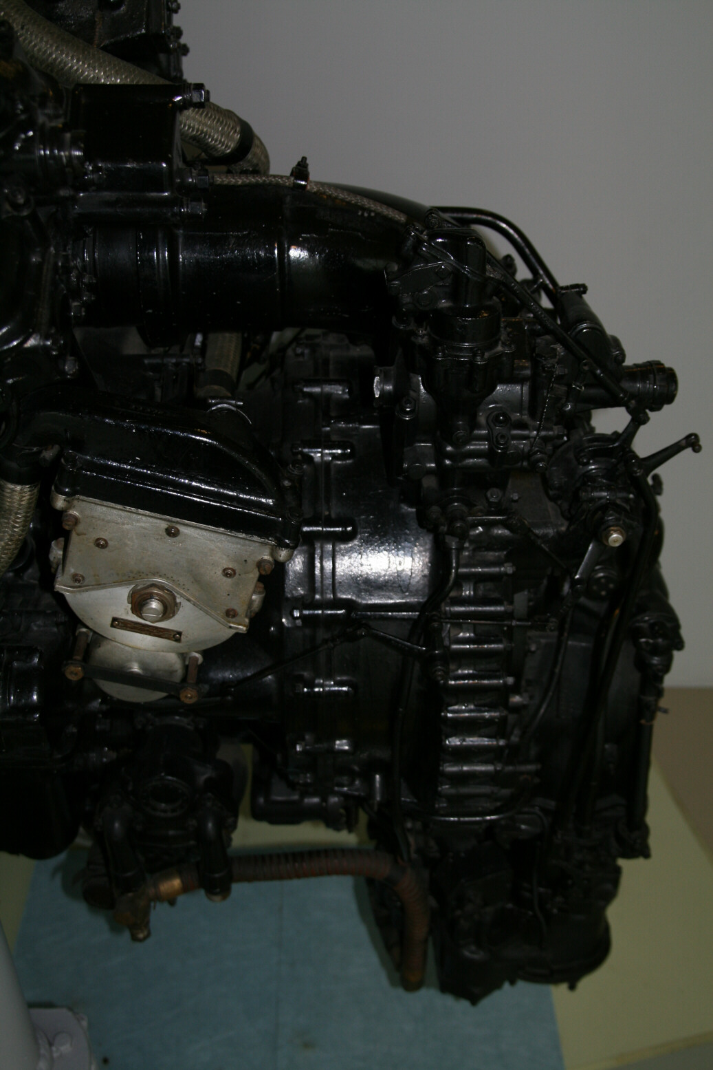
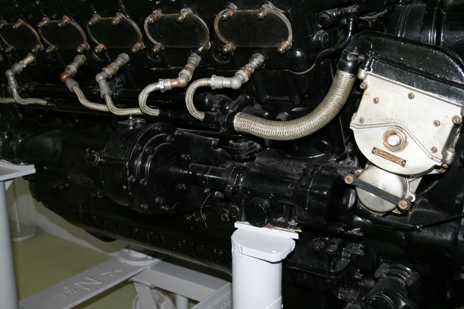
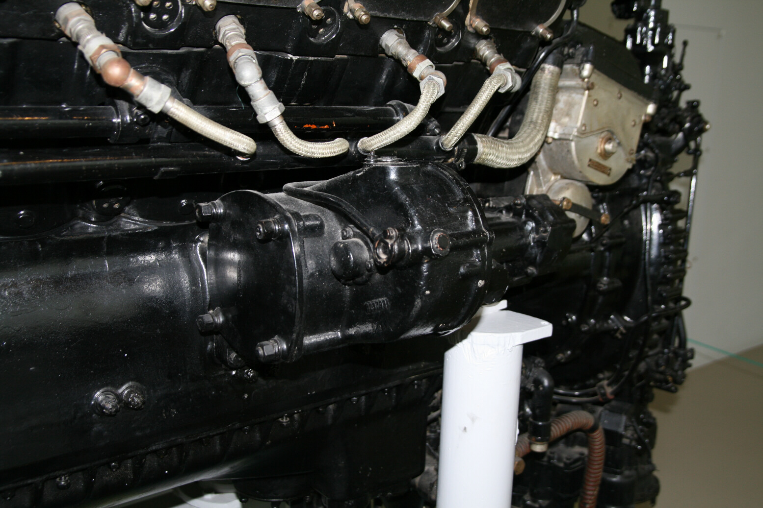
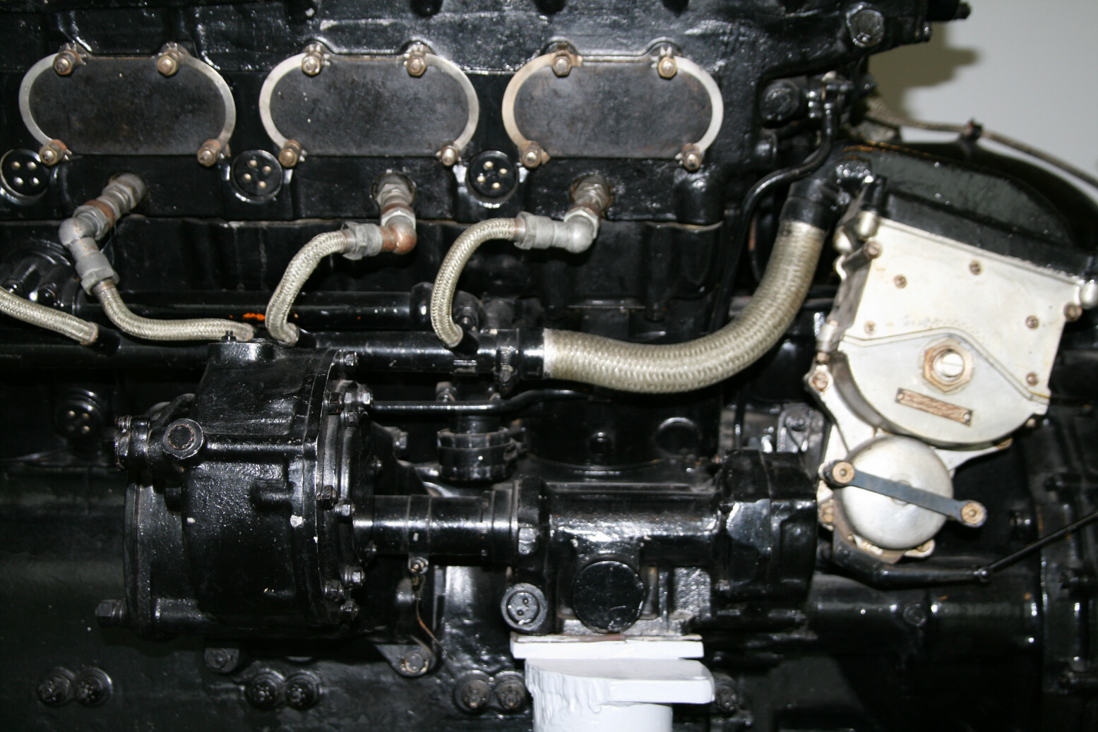
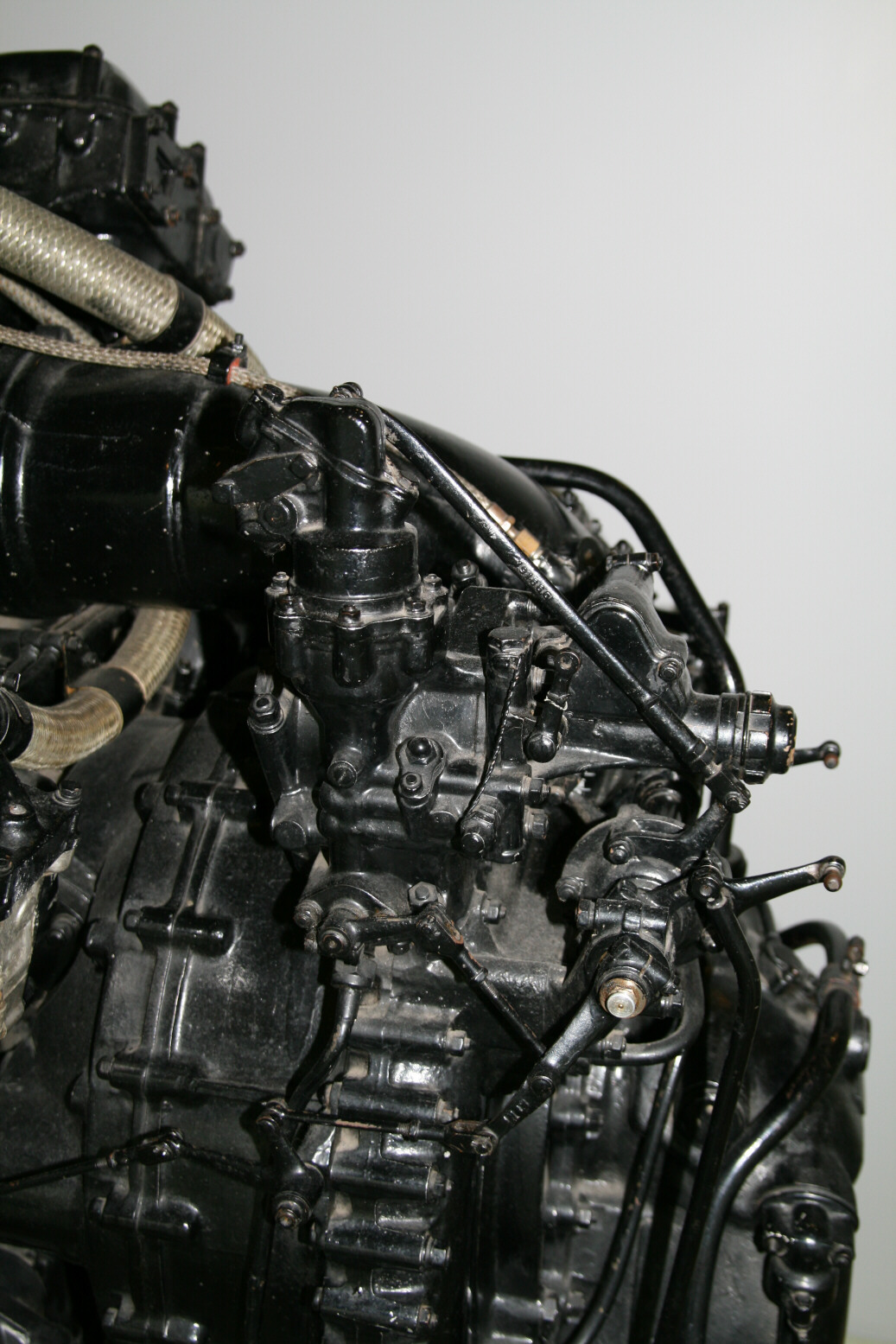
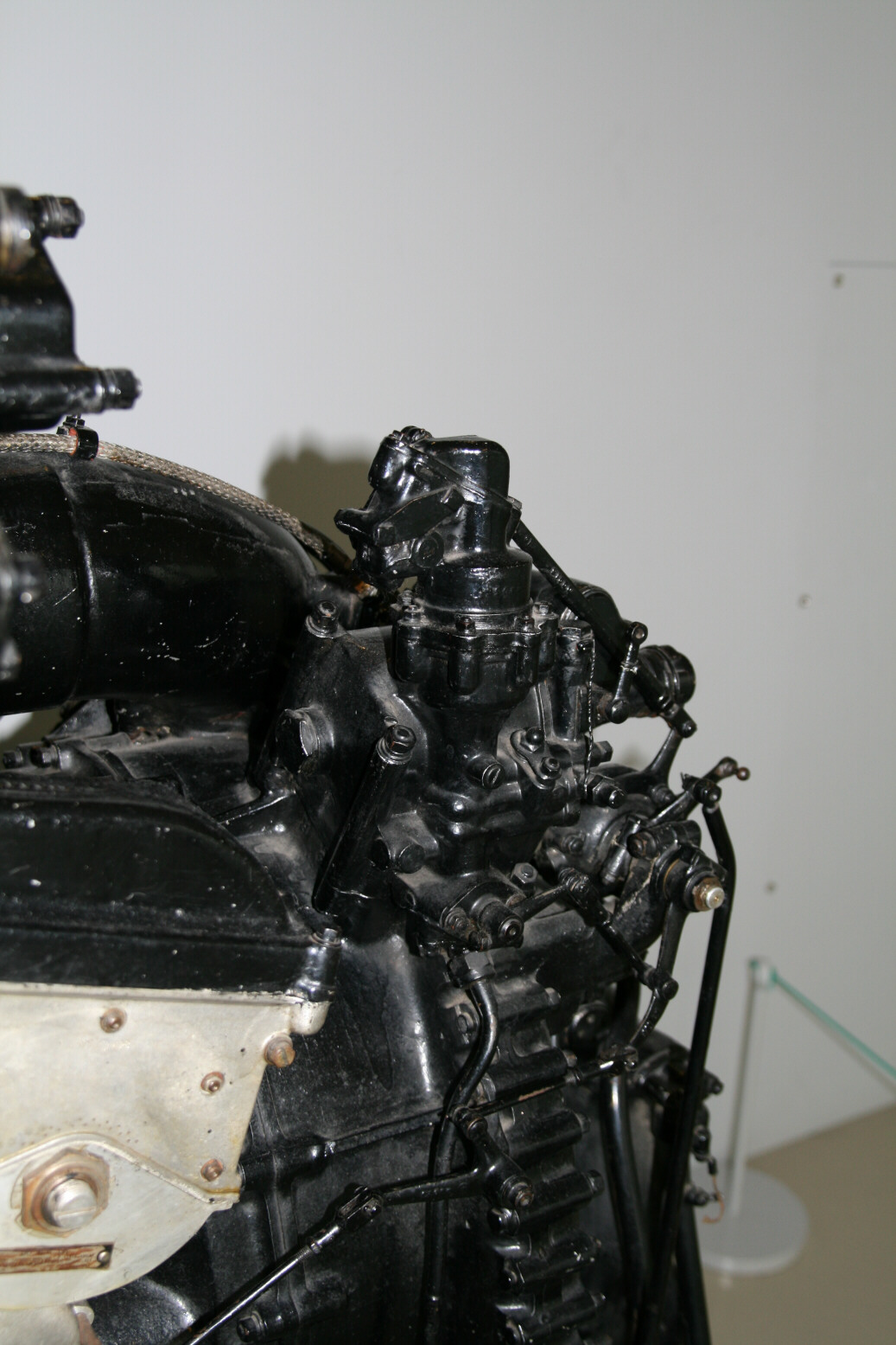
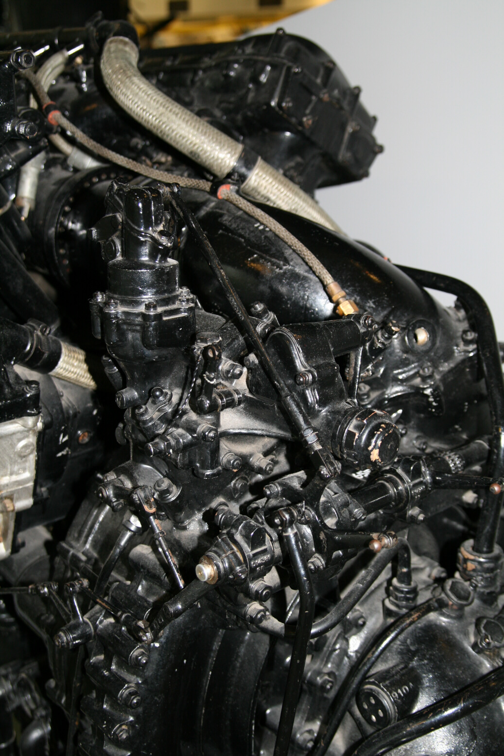
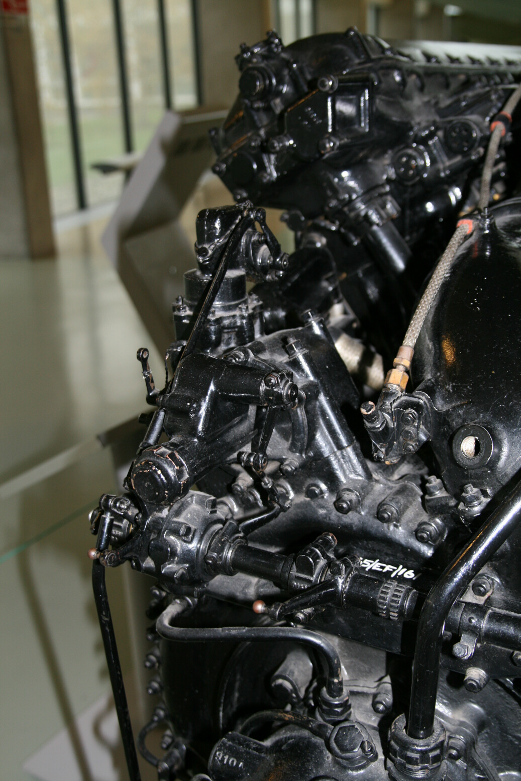
Photos 4 through 6 show the port side of the supercharger at various angles. On top of the supercharger is the automatic boost control unit, connected by rods to the control lay shaft. Below that is the main spiral of the supercharger. The air intake is towards the bottom and back. Below the main spiral is the carburettor (the unit to where the ribbed fuel pipe goes. This part is completely different from that of the Merlin III. The carburettor with the dual butterfly throttles is directly behind the ribbed fuel line, with an additional unit a bit right towards the viewer. There is another unit underneath the wider supercharger ring (the one with smaller diameter and fewer bolts) whose purpose is unknown to me.
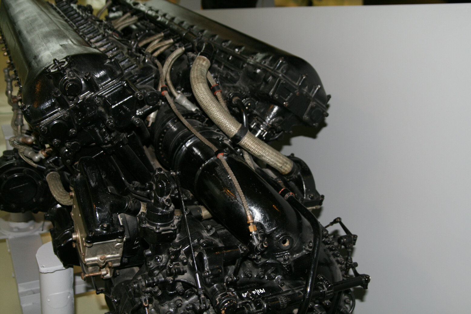
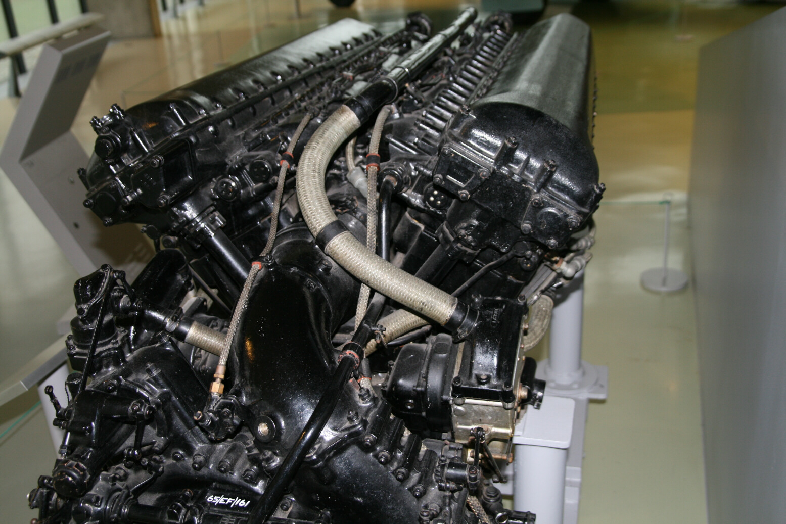
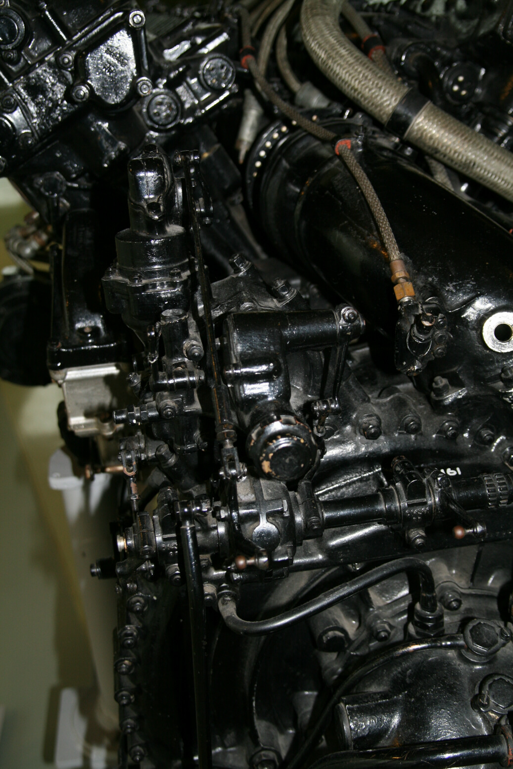
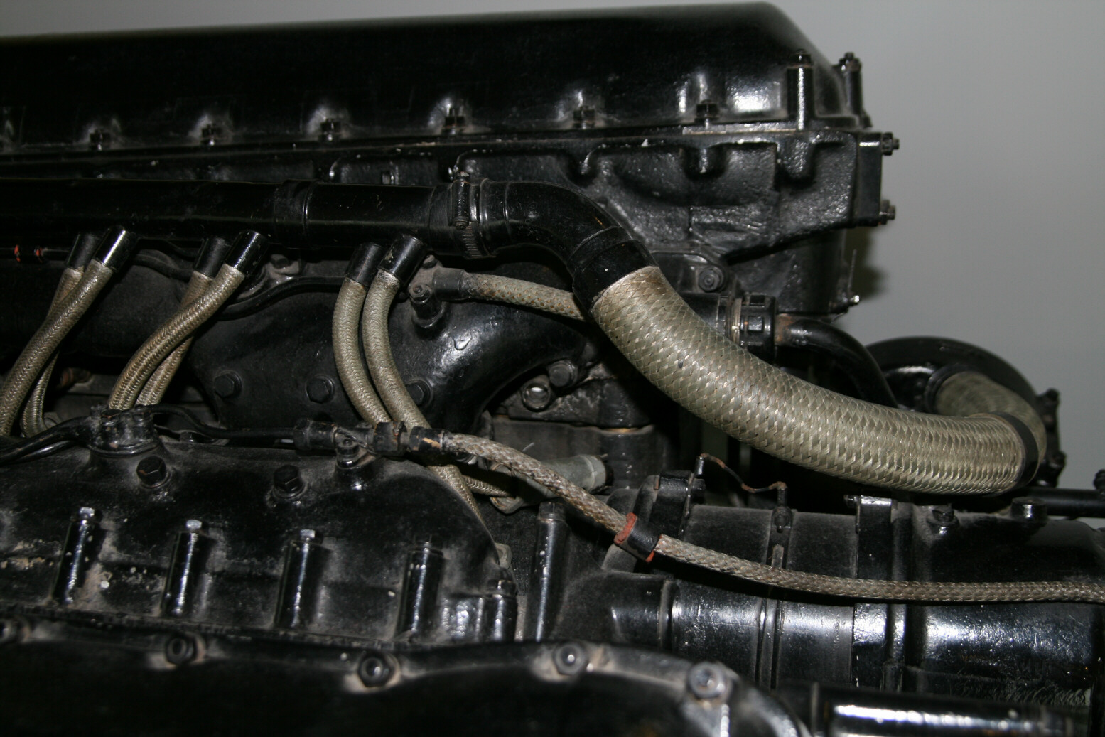
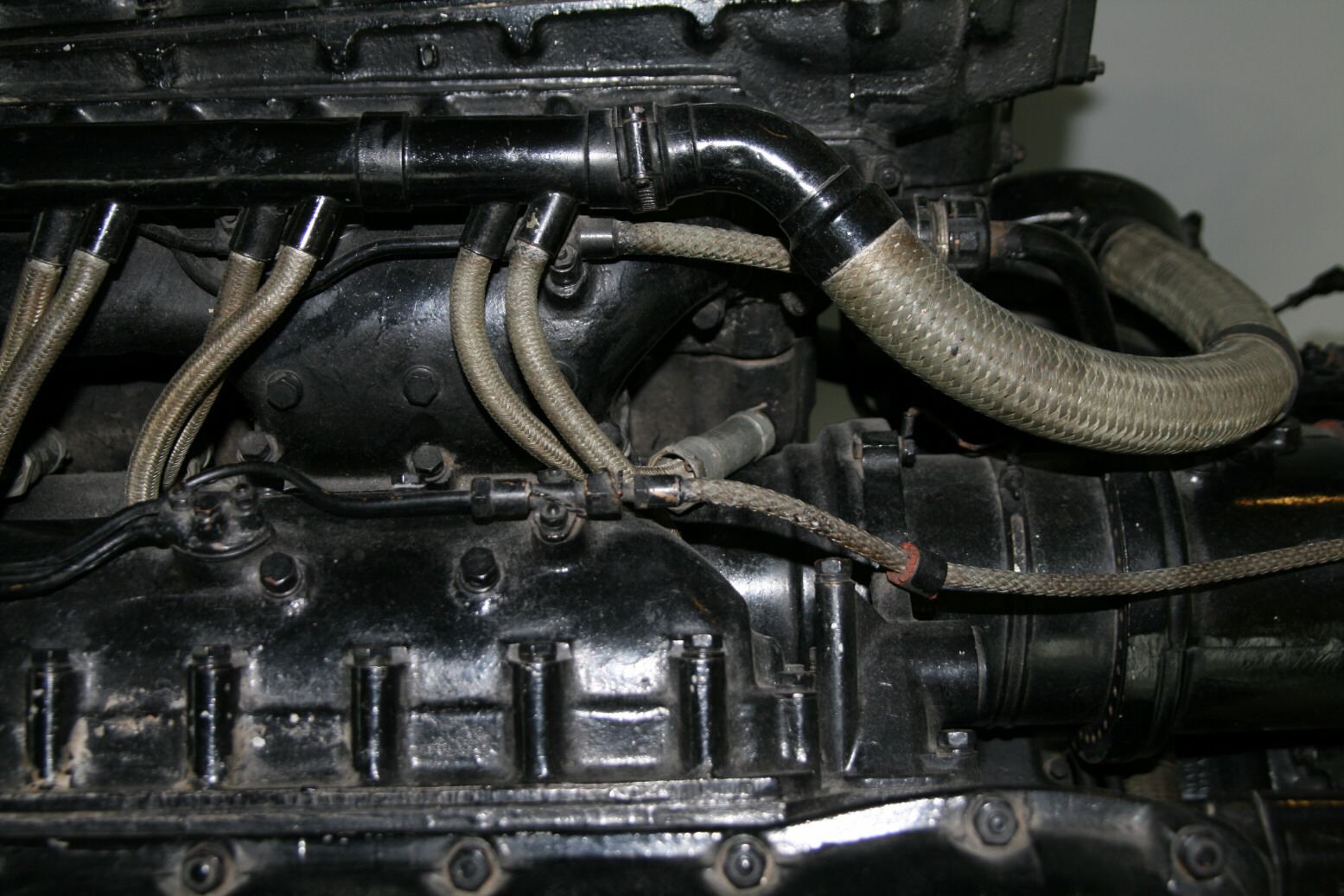
Photos 7 through 9 show the top of the back of the engine from various angles. Well visible are the big pipe from the supercharger, the ignition wiring from the starboard magneto to the inner spark plugs, and the cam shaft drives coming up from below to the end of the cam shaft unit.
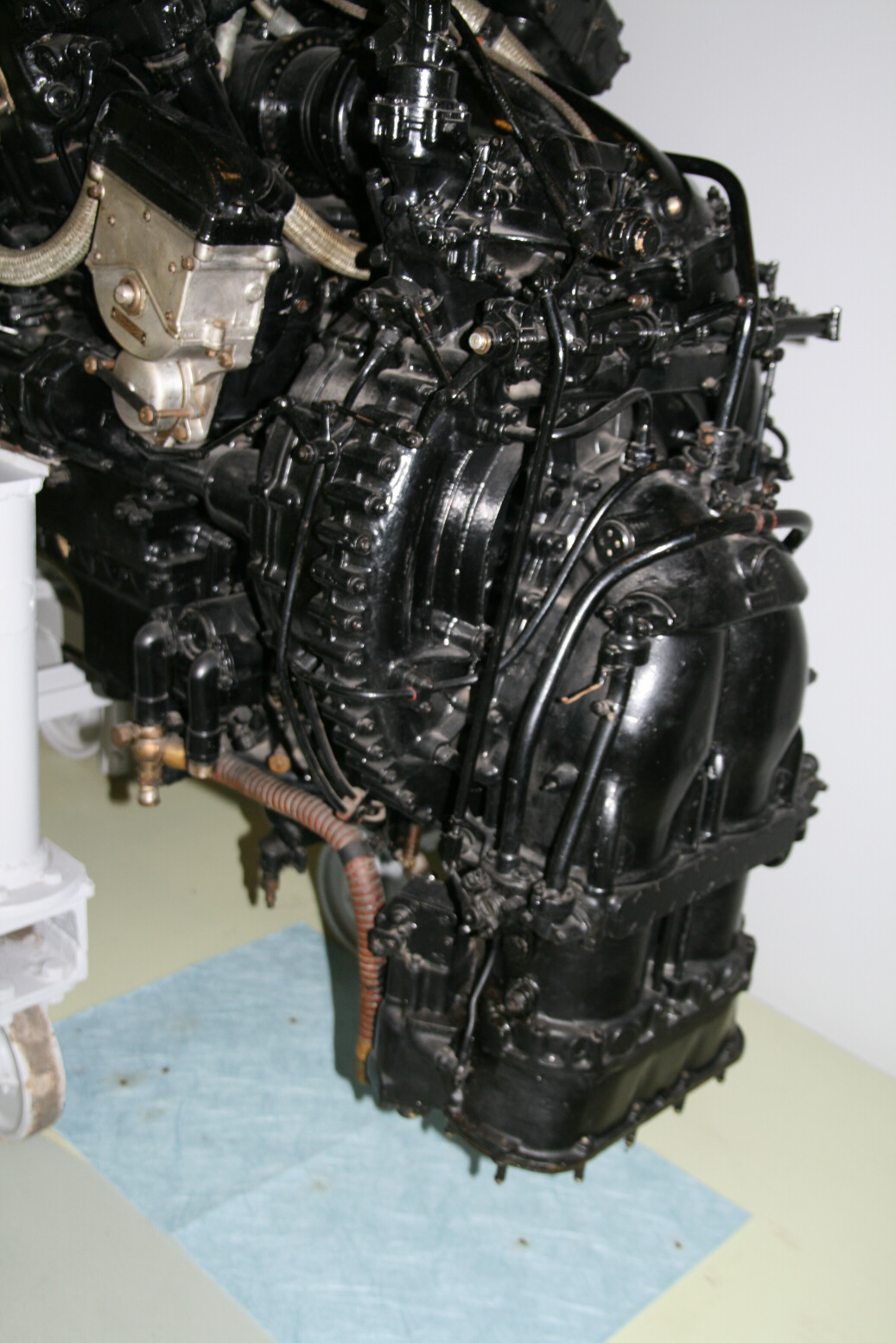
Photo 10 gives a view of the supercharger from the left. The cap on the two vertical pipes of the air intake is a cooling unit (absent on Merlin III). Note the control rod going down from the engine control lay shaft to the unit mounted on the side of the carburettor (the left-most of the three vertical pipes in the photo center - though this one isn't a pipe).
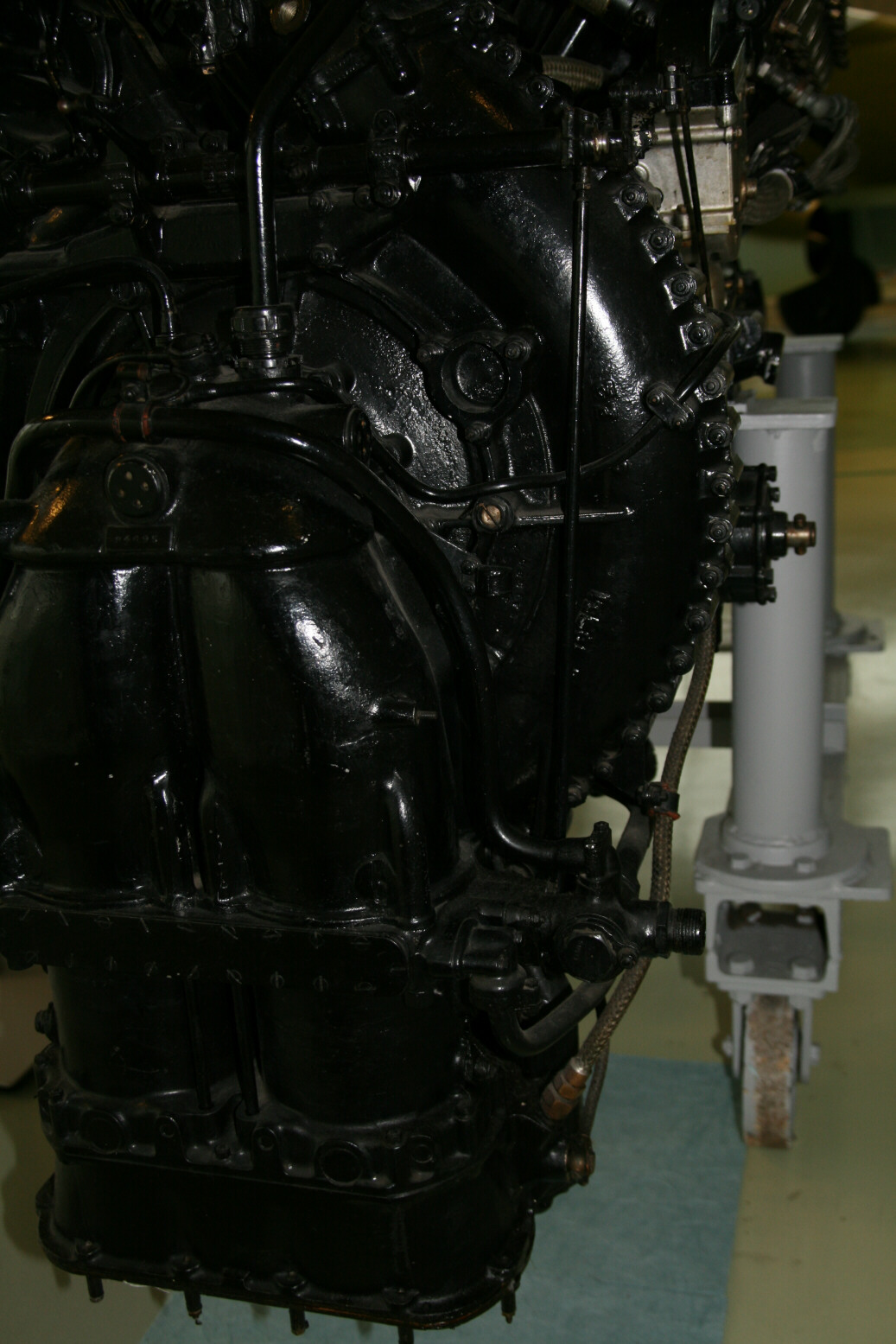
Photo 11 shows the bottom back of the supercharger on the starboard side. The pipes here are all cooling (also the two vertical pipes almost merged with the mantle).
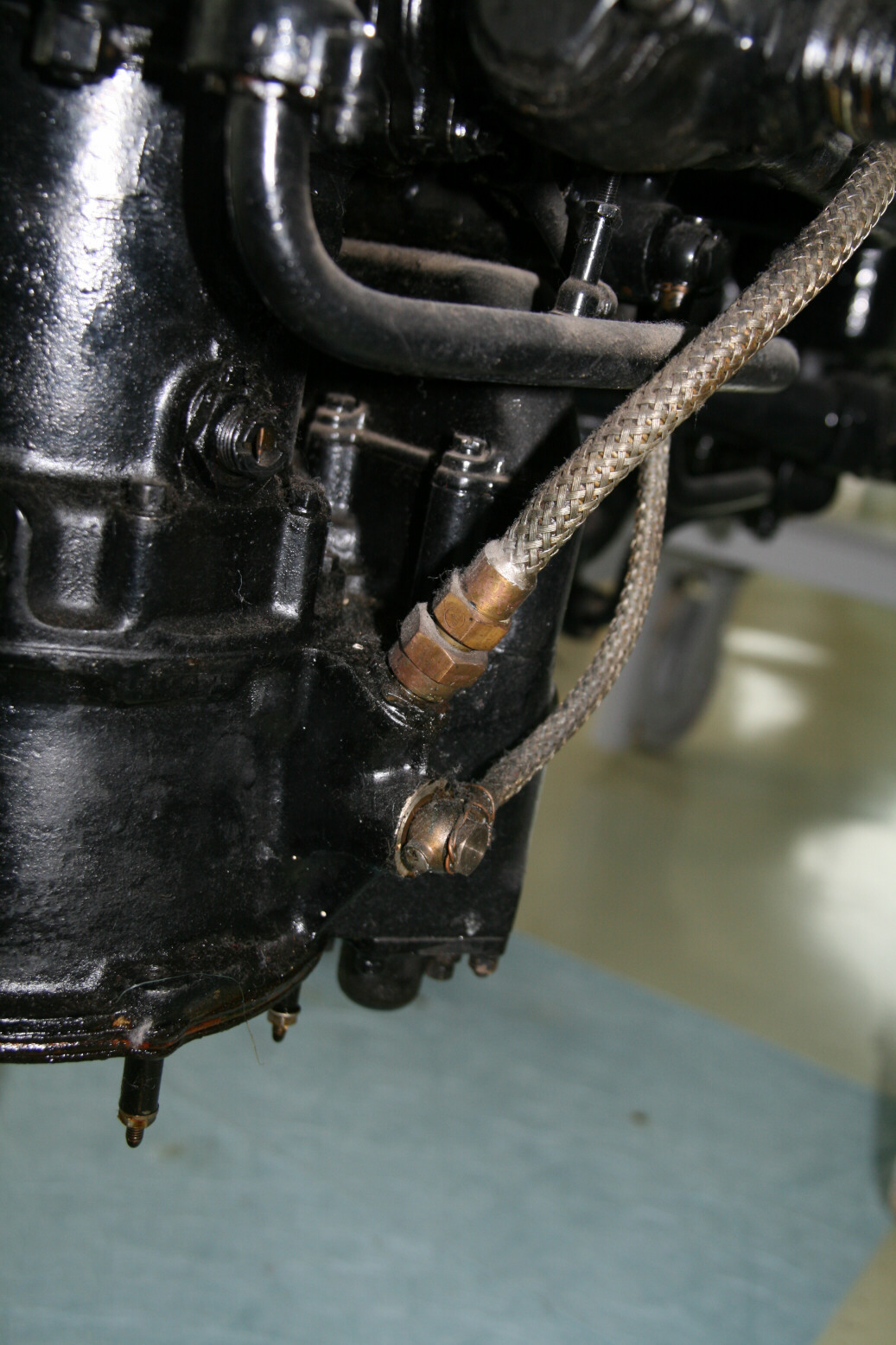
Photo 12 shows a detail from the bottom of photo 11.
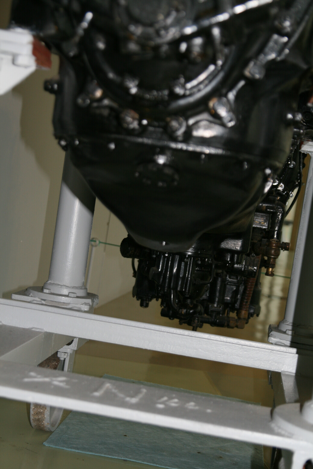
Photos 13 through 15 show the bottom of the engine. Photo 13 is from the front.
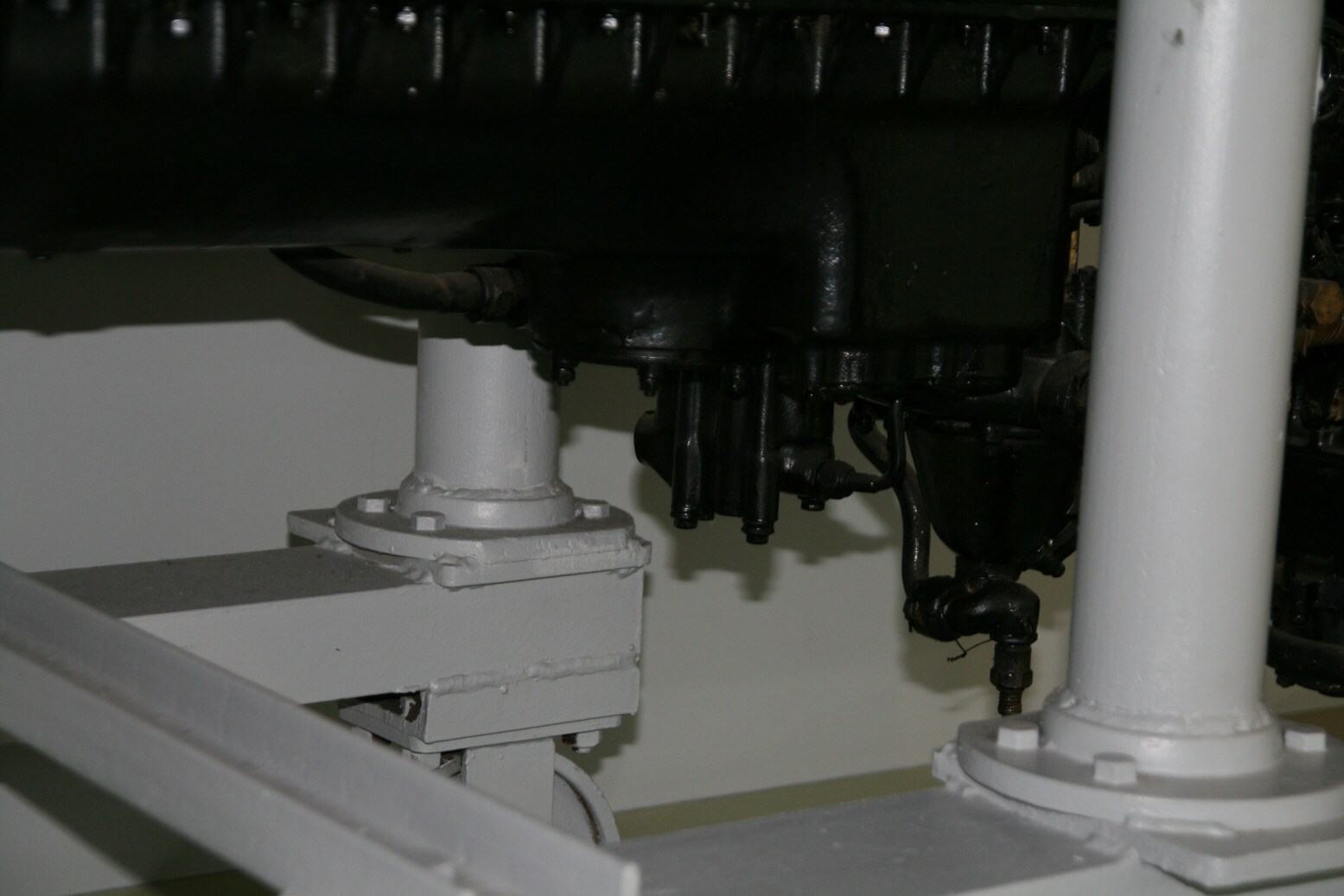
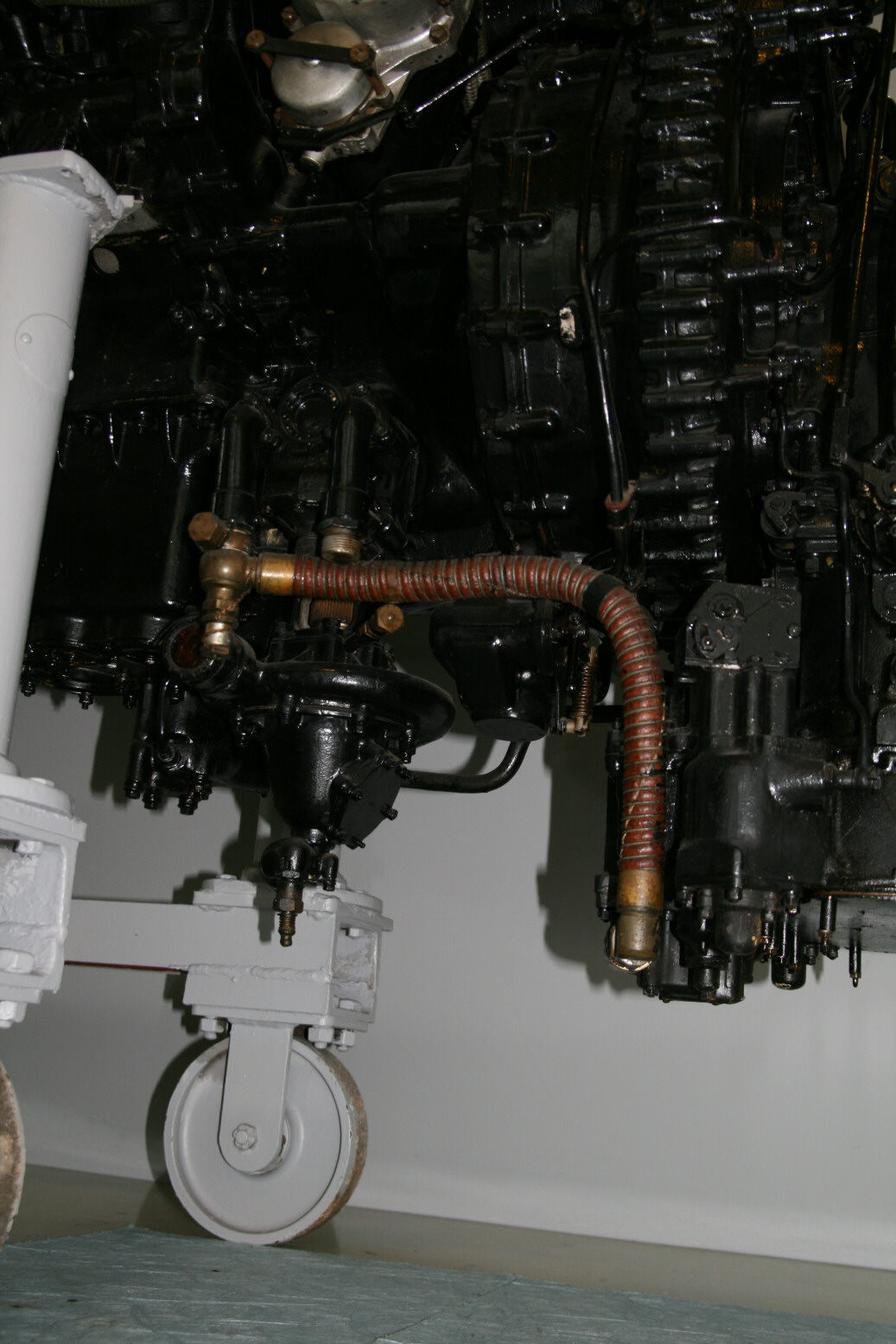
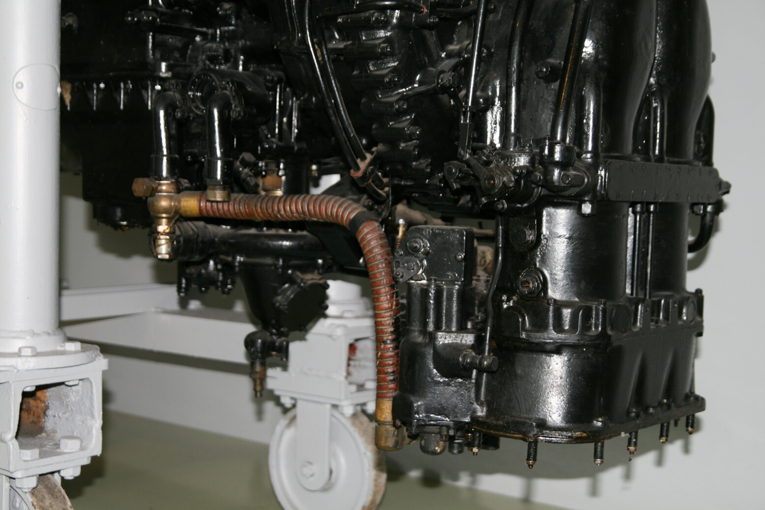
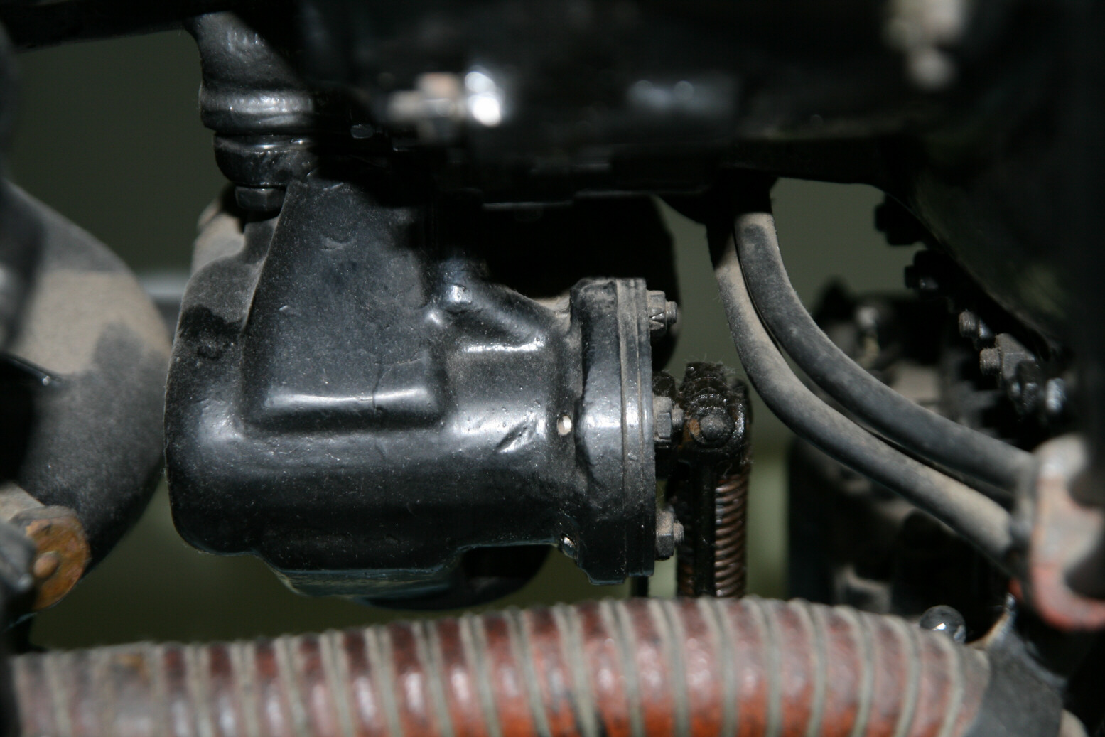
Photo 14 is from the port side and shows the oil pump in the center and the coolant pump (the conical unit) to the right.
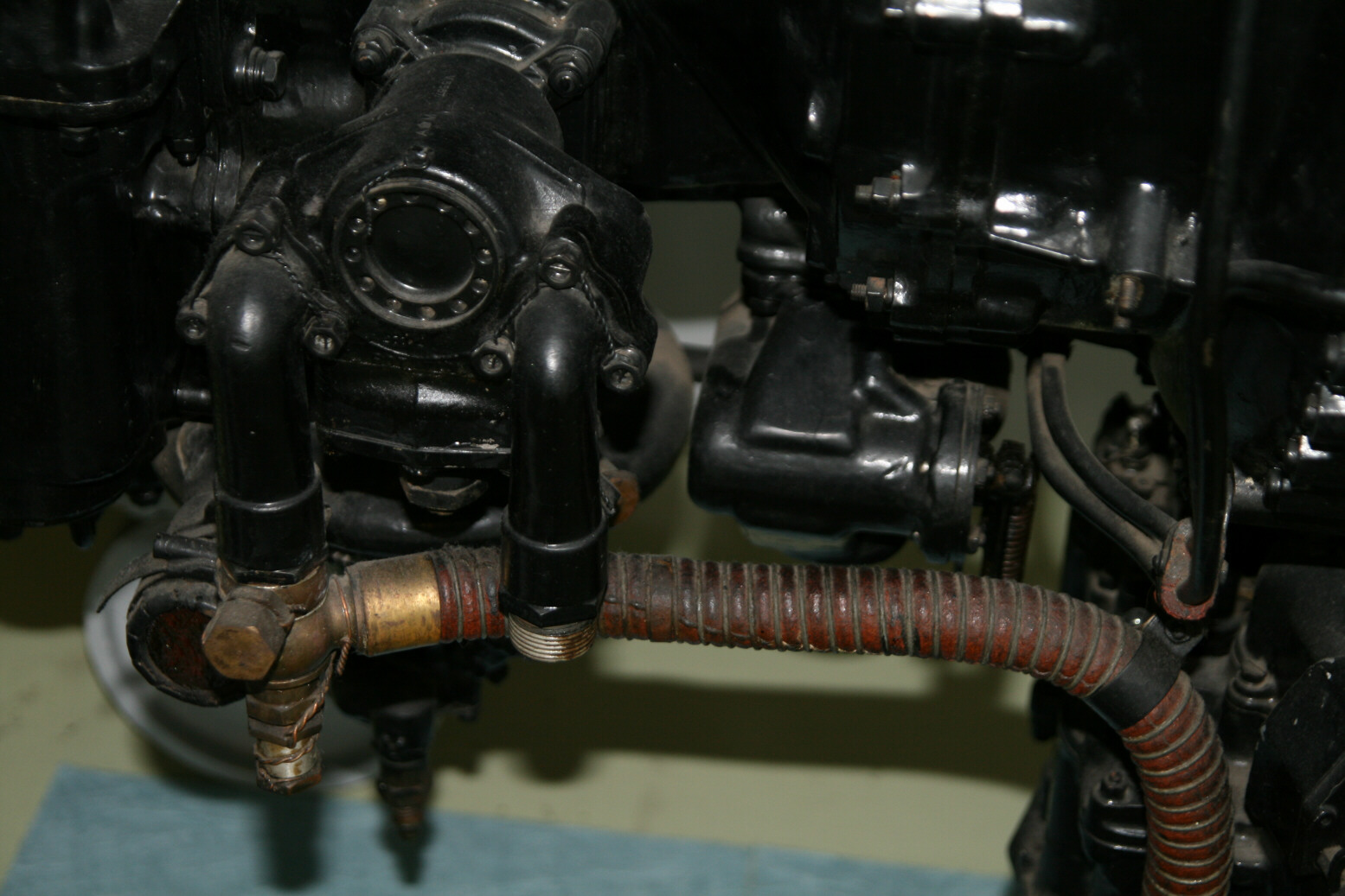
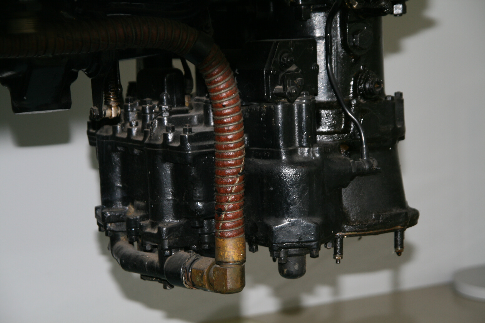
Photo 15 shows the coolant pump from the starboard side. The big flange is where the pipe from the radiator is connected. The curly pipe goes to the supercharger inlet. The intermediate-size pipe running horizontally is where the starboard coolant pipe for the cylinder bank is connected (absent on this engine but visible on other ones). A similar pipe connects to the port side.
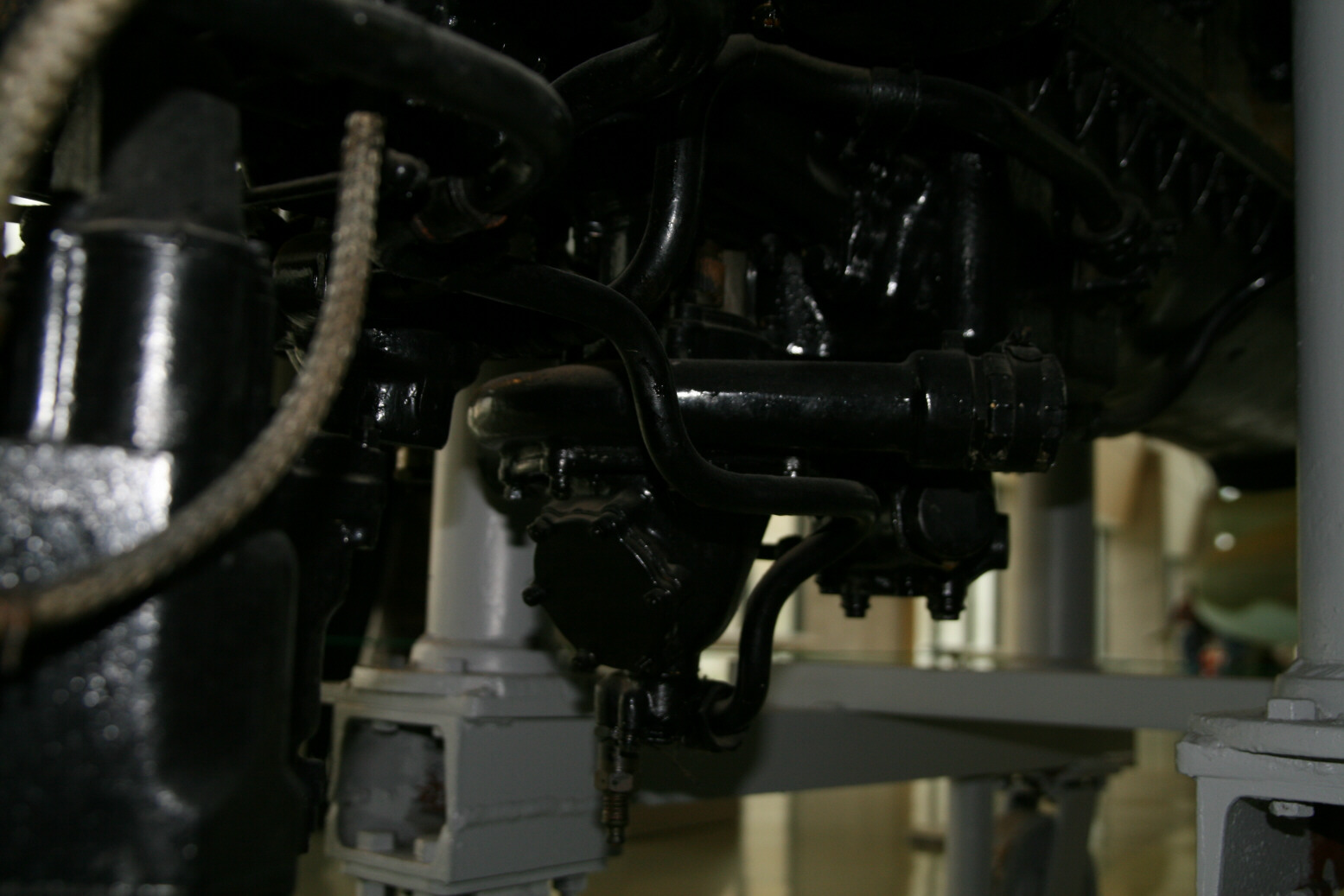
Photos 16 through 19 all show bottom detail from the port side.
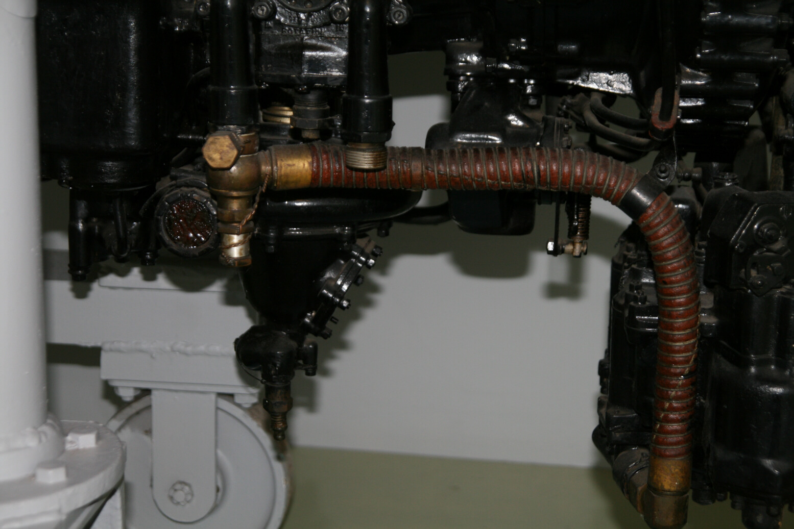
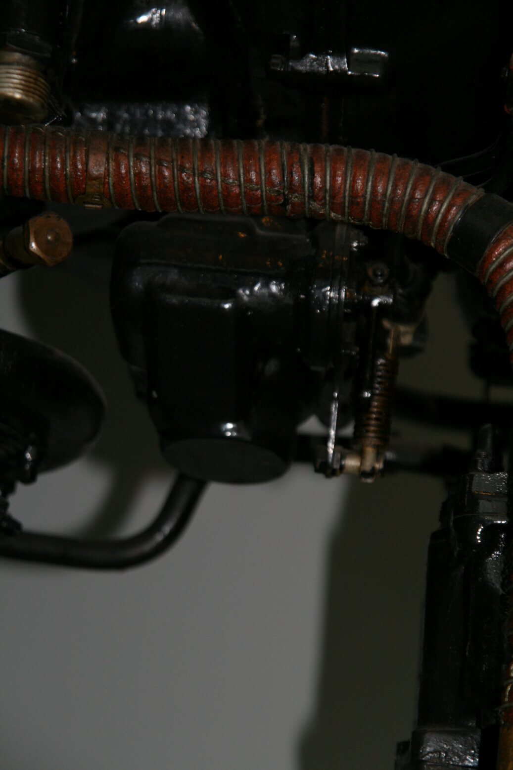
Photo 16 has the ribbed fuel line from the fuel pump (most of the fuel pump is outside the photo) to the carburettor in the center. Just to the left of the fuel line connection is the outlet for the port cylinder bank coolant pipe (the plug has a slightly brownish color) coming from the coolant pump. Left of that is again the oil pump. The unit with the spring, behind the fuel line, is of unknown purpose.
Photo 17 shows a better view of the fuel pump (roughly a 'horse-shoe' like shape) with the two vertical pipes, the right-hand where the fuel line from the fuel tanks connects, and the out pipe on the left.
Photo 18 shows a view of the carburettor on the front bottom of the air intake.
Photo 19 shows the whole area again.
Photos 20 through 22 give more detailed shots of the same area.
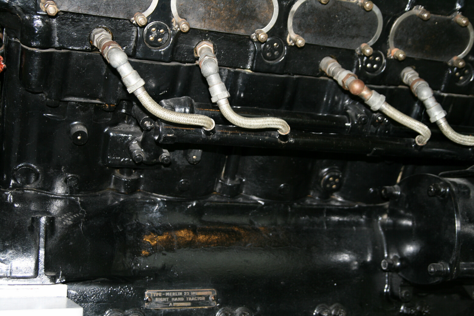
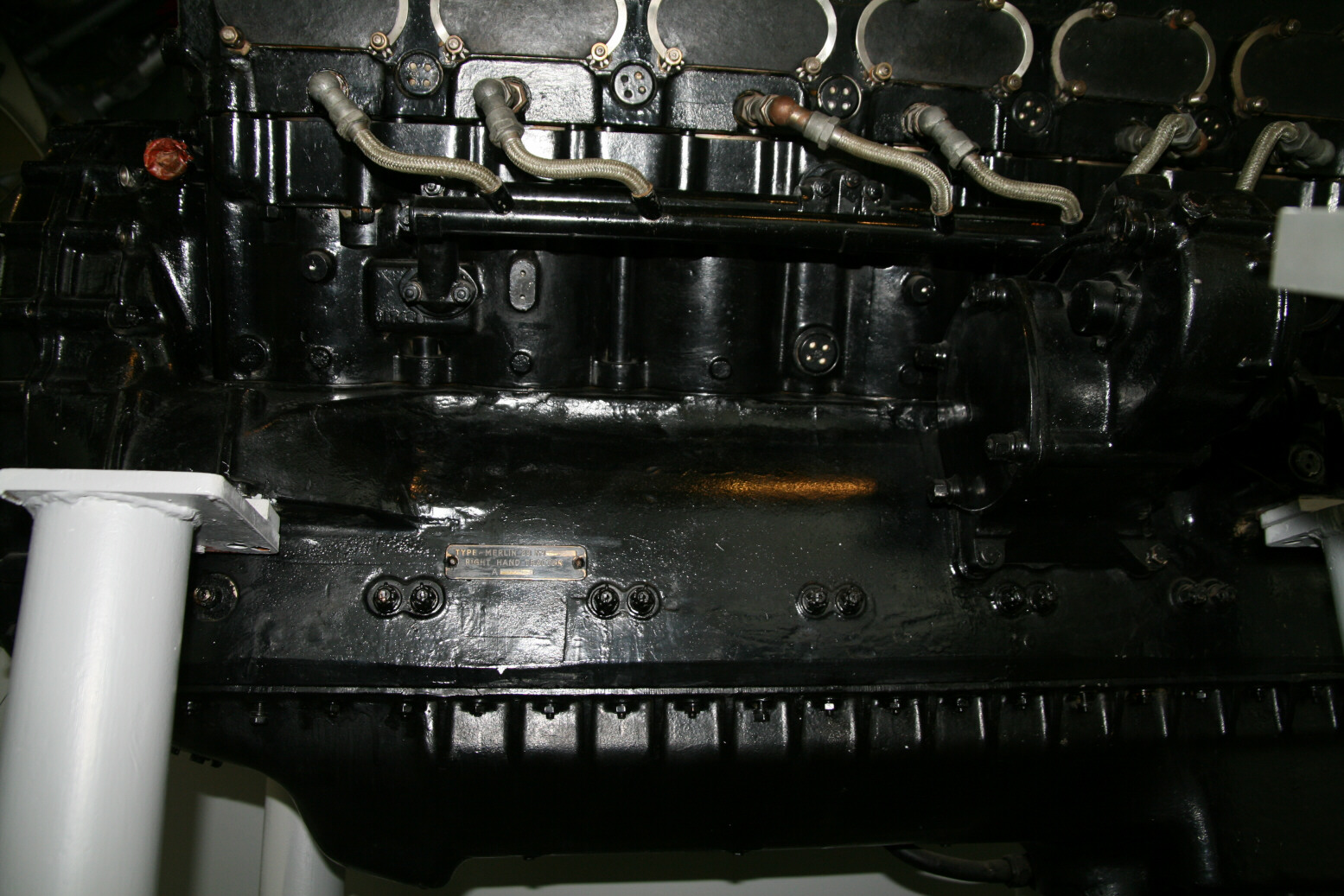
Photos 23 through 26 show views of the port cylinder side wall. In all photos the nearly elliptical metal plates cover the exhaust outlets.
In photo 23 the left-most spark plug visible is the frontmost one. The ignition wiring comes from a pipe that is positioned a bit away from the side wall. Behind it, running horizontally is a coolant pipe. This pipe runs from between cylinders 1 and 2 (front) with a small vertical pipe coming out of the end unit at the bottom. Between cylinders 2 and 3 there is another vertical pipe that splits off from the horizontal pipe (an, here invisible, T-connection). Between cylinders 3 and 4 is another unit and this is where the coolant pipe from the pump enters (from the bottom). Once again there is a small vertical pipe between the cylinders, here with a removable plug (the part with the four holes). The horizontal pipe runs further back.
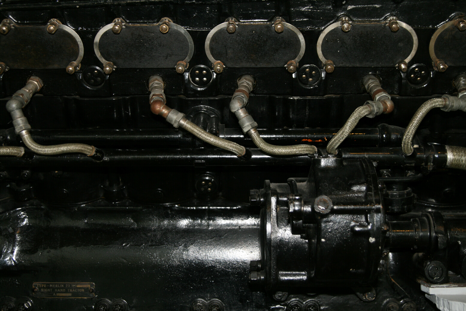
Photo 24 gives a view further to the back. The end of the horizontal pipe is seen bending down between cylinders 5 and 6. The prominent unit bottom right is the drive for the (missing) generator.
Photo 25 gives a view from below. The red tube plugs up a hole where a (? coolant) pipe should be. This pipe comes slanting down towards the back along the engine side at about 45°, then at about the level of the engine bottom part (where the numerous bolts are) goes horizontally towards the back.
Photo 26 shows a view from the back.
Photos 27 and 28 show the generator drive in more detail.
Photos 29 through 33 show the automatic boost control unit, which is hell to photograph (at some angles it fails to stand out against the background) and due to its complex shape, even more hellish to scratchbuild.
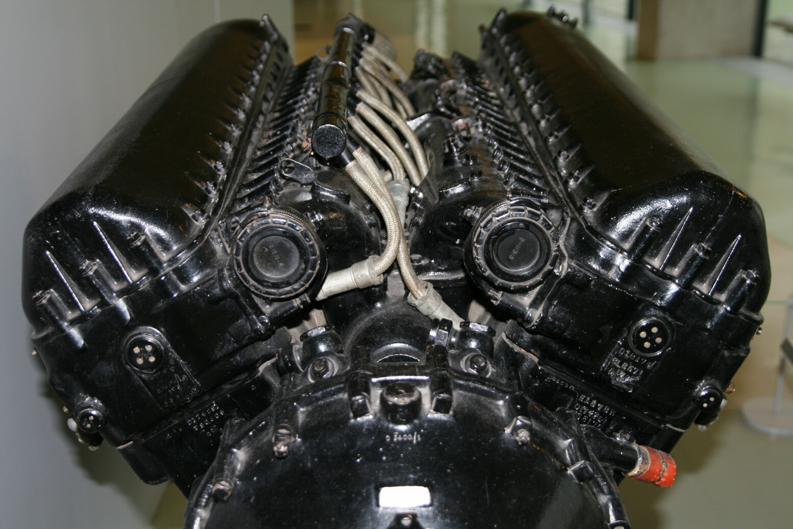
Photo 34 is a front view of the top of the engine. The asymmetrical position of the ignition wiring is obvious. The two round plugs on either side at the front are where the coolant pipes connect to the header tank.
Finally some photos of the top of the engine.
Photos 35 and 36 start at the back. The bulging parts between the cylinder banks (an area that obviously is not solid) form part of the fuel inlet system. The smaller braided lines are oil pipes that feed the thinner pipes further towards the front.
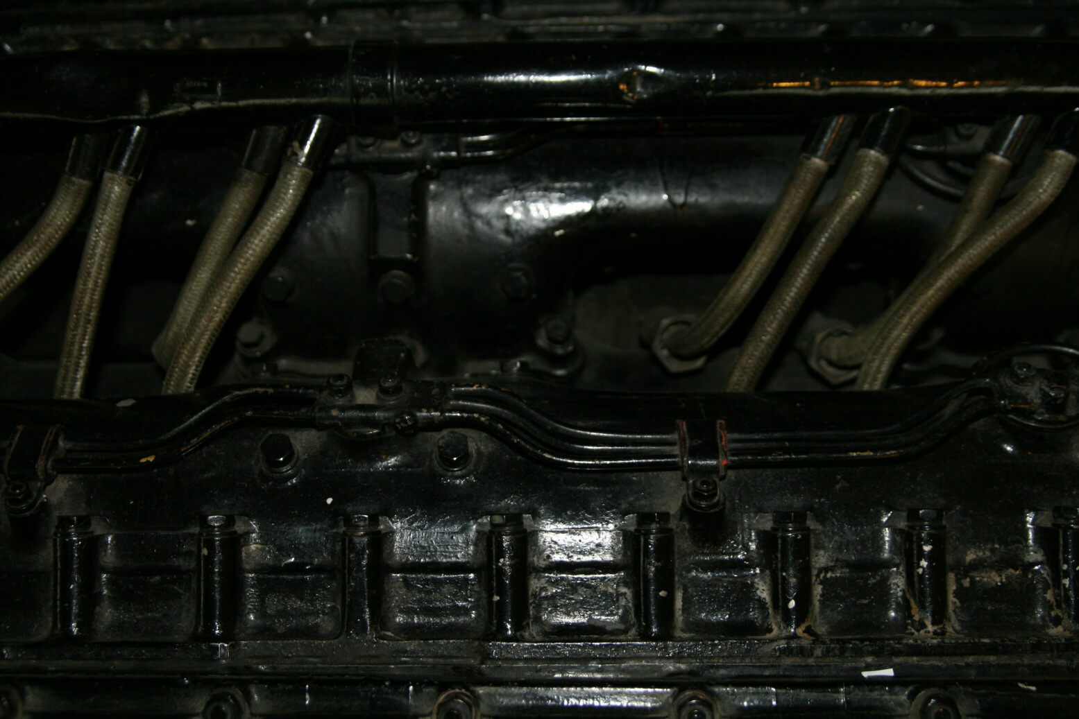
Photo 37 is further forward, with ignition wiring, spark plugs and oil lines.
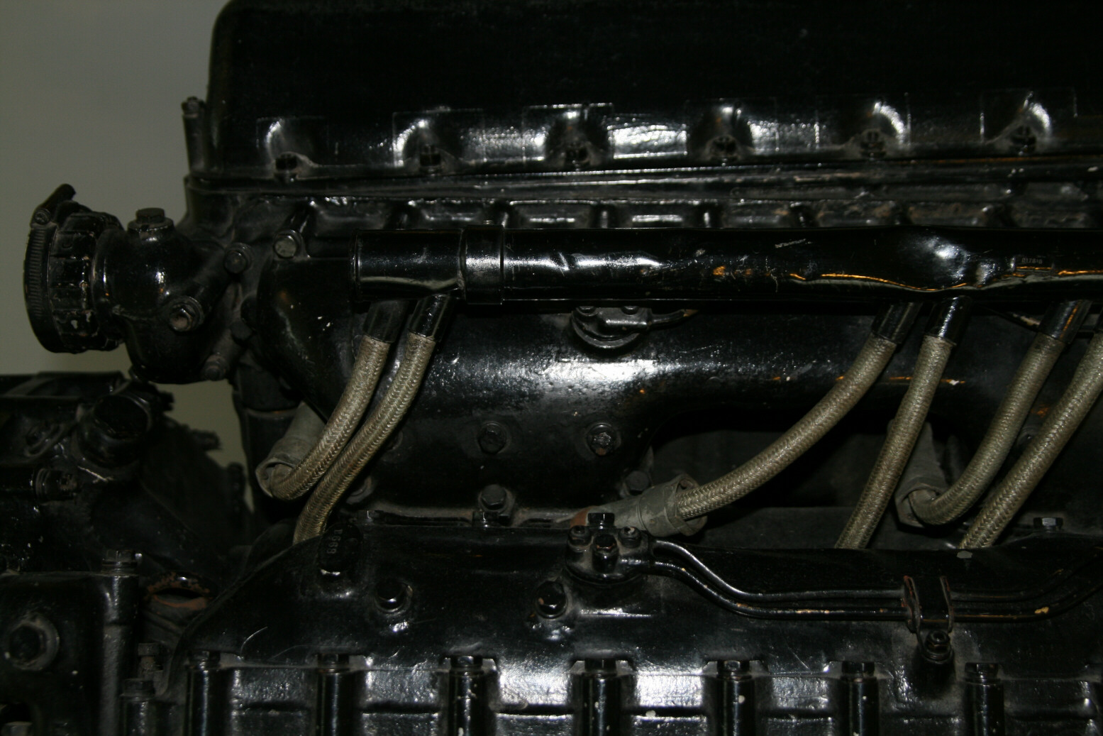
Photo 38, even more forward, shows again the bulges of the fuel inlet system with gaps where the ignition wiring goes to the spark plugs. The outlet to where the pipe to the header tank connects is well shown.
© Max Otten 2013
This article created on Sunday, January 05 2014; Last modified on Thursday, March 31 2016