
Rolls-Royce Merlin III
Photos By Max Otten
The Merlin III (Roman numeral 3, later on normal numbers were used for higher marks) was the engine that powered (amongst others) the Spitfire and Hurricane during the Battle of Britain. The pictures were taken at the RAF Museum at Hendon and the Science Museum (both in London, England). The pictures are from three different Merlin IIIs, two stand-alone and one that is part of the Hurricane wreck.
Merlin III, Science Museum
Photos were taken at the Science Museum, London, in 2011.
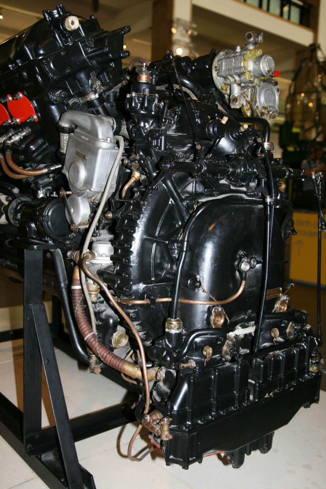
This particular engine is quite nice as it does have a coolant header tank, hydraulics pump, compressor and generator still in place. If some of the photos of the bottom look a bit grayish or hairy on top surfaces, that is because the engine needs a bit of cleaning. It is not a feature of the Merlin engine.
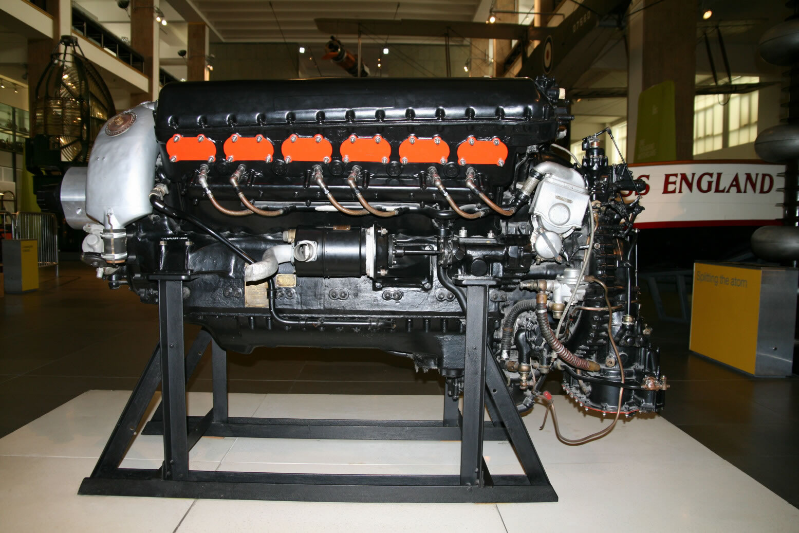
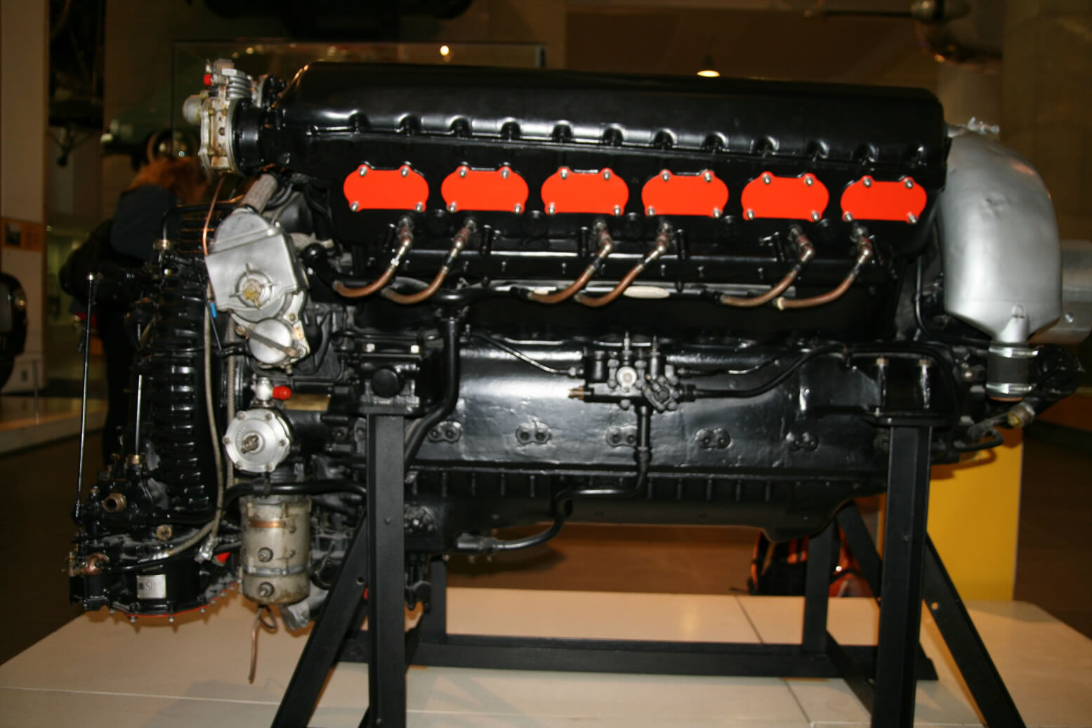
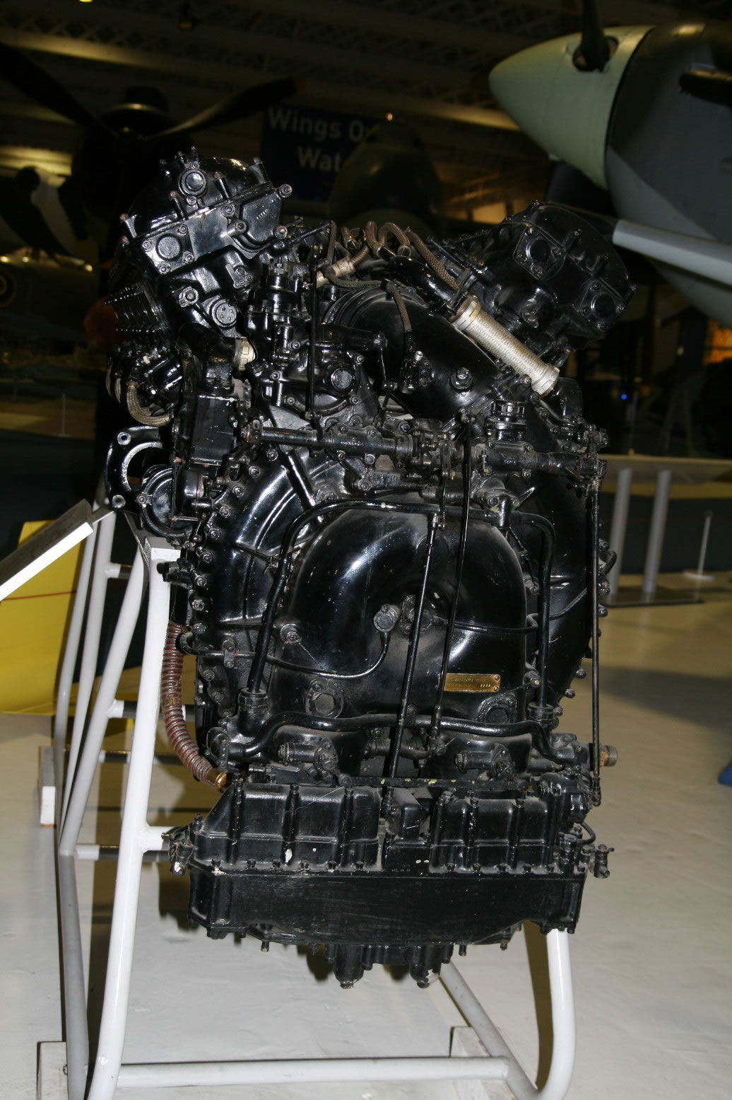
Photo 1 gives a good view of the whole engine, port side. The red plates cover the exhausts. Above that you see the camshaft cover, with a typical flat area where often times you will find the text ROLLS ROYCE in white or red letters. Difficult to see in this picture, but the cam shaft covers actually protrude further at the back than the cylinder banks and that is the location where the cam shaft drive comes up from below. Roughly in the center is the generator with its air intake (the bent pipe). From the generator an electrical line would run along the engine bearer towards the back and connect up to the suppressor (a box-like unit, not present on this engine).
The 'silver' unit towards top right is the port magneto which provides the ignition for the outer spark plugs (on either side of the engine), so one cable runs out from its top towards the front, the other is at the back, crosses over the supercharger and connects to the starboard side plugs. The 'silver' unit below the magneto is probably the carburettor. On later marks of the Merlin the carburettor is mounted against the front lower part of the air intake, but there appears to be no such unit here. The ribbed pipe that is closest to the viewer runs from this unit to the air intake part which is at the bottom of the supercharger (with a red blanking plate). The other ribbed pipe comes from the fuel pump.
At the back end is the supercharger from which you can see the numerous bolts on the main ring and behind that the complicated structure of the air intake.
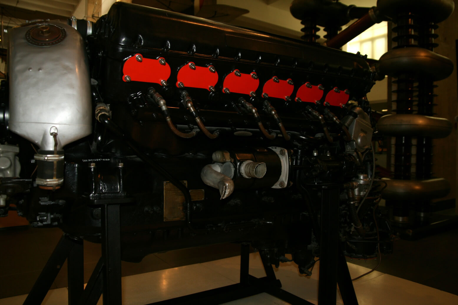
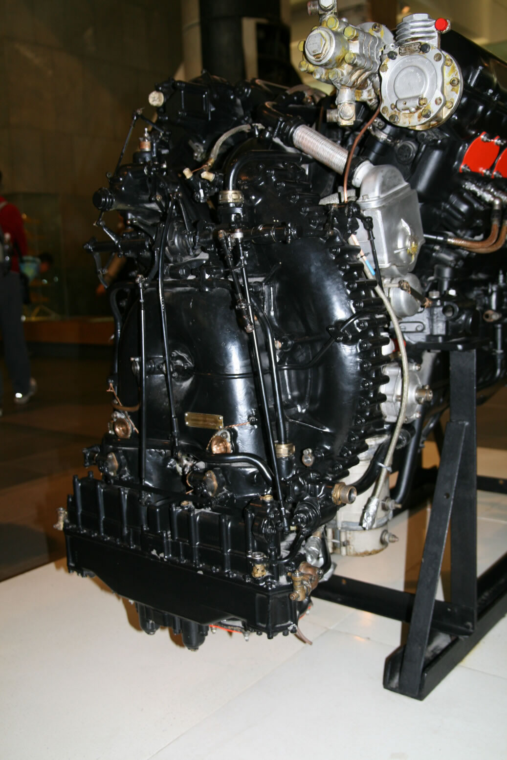
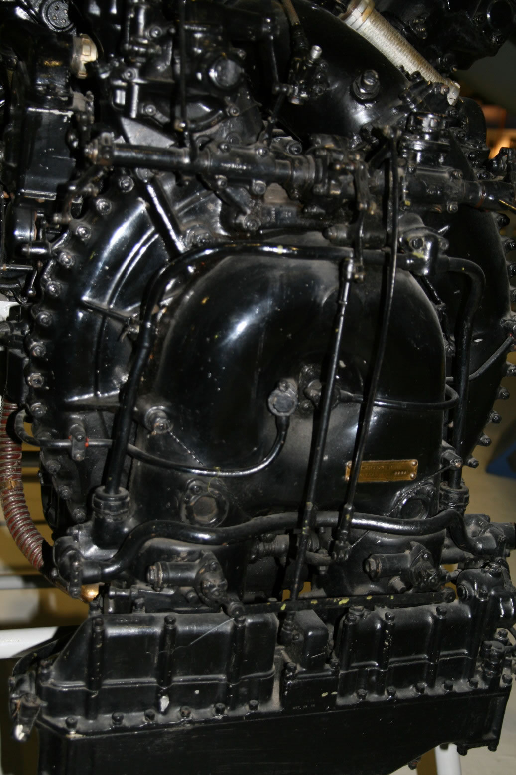
Photo 2 is from the same side, but looking more from the front. Well shown are the generator and the engine data plates.
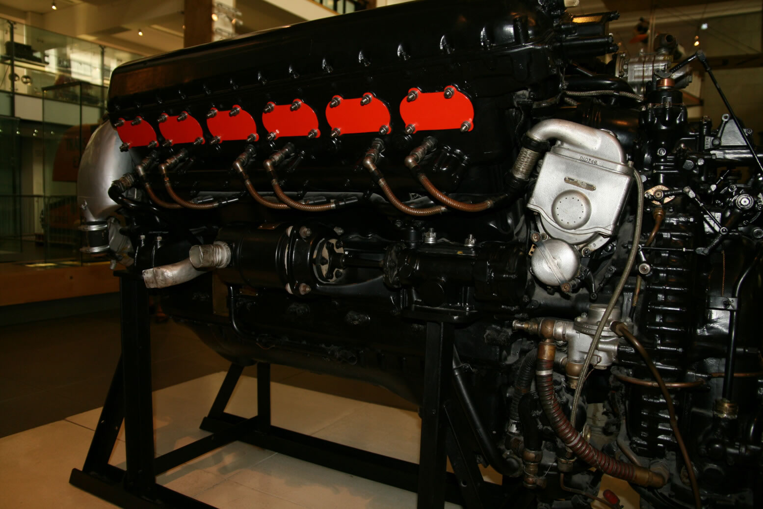
Photo 3 again the same area but looking more from the back.
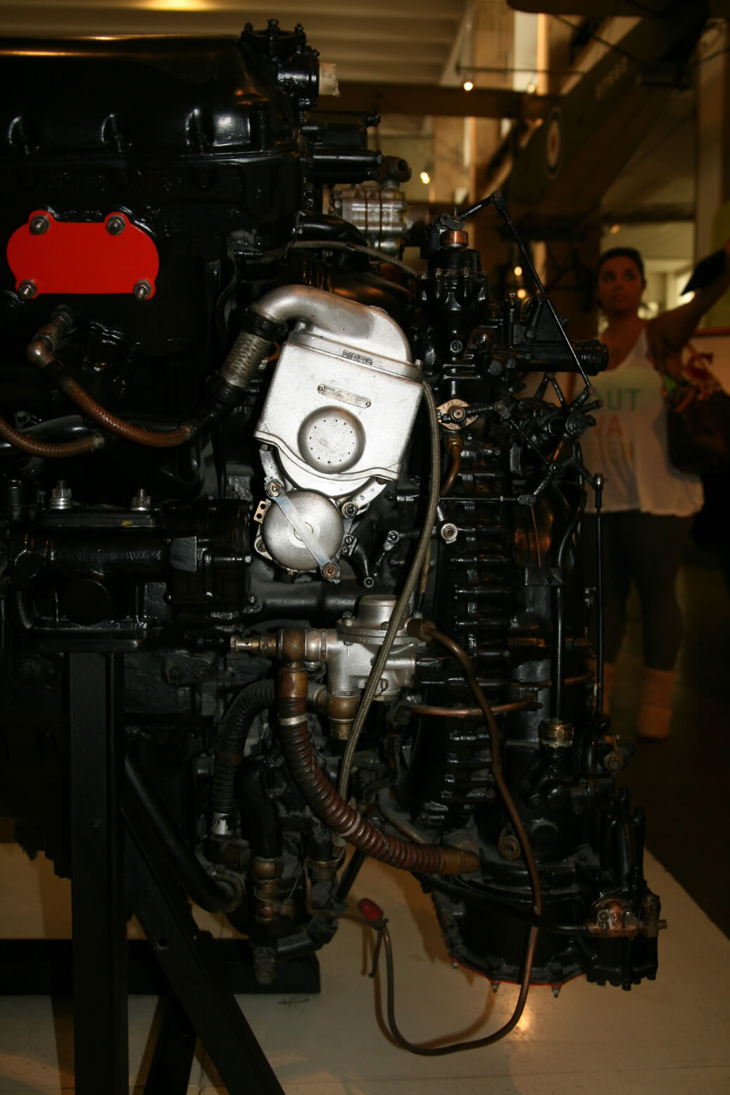
Photo 4 shows the port magneto. Note the very fine control rods for the advance (the circular unit of the bottom part of the magneto) coming from the main lay shaft at the back of the supercharger. The cable connection coming out of the magneto has two black rings with braided wire in between. If you look well, you will see that the cylinder bank terminates to the left of the lower ring, with the vertical cam shaft drive behind the solid part of the magneto connection.
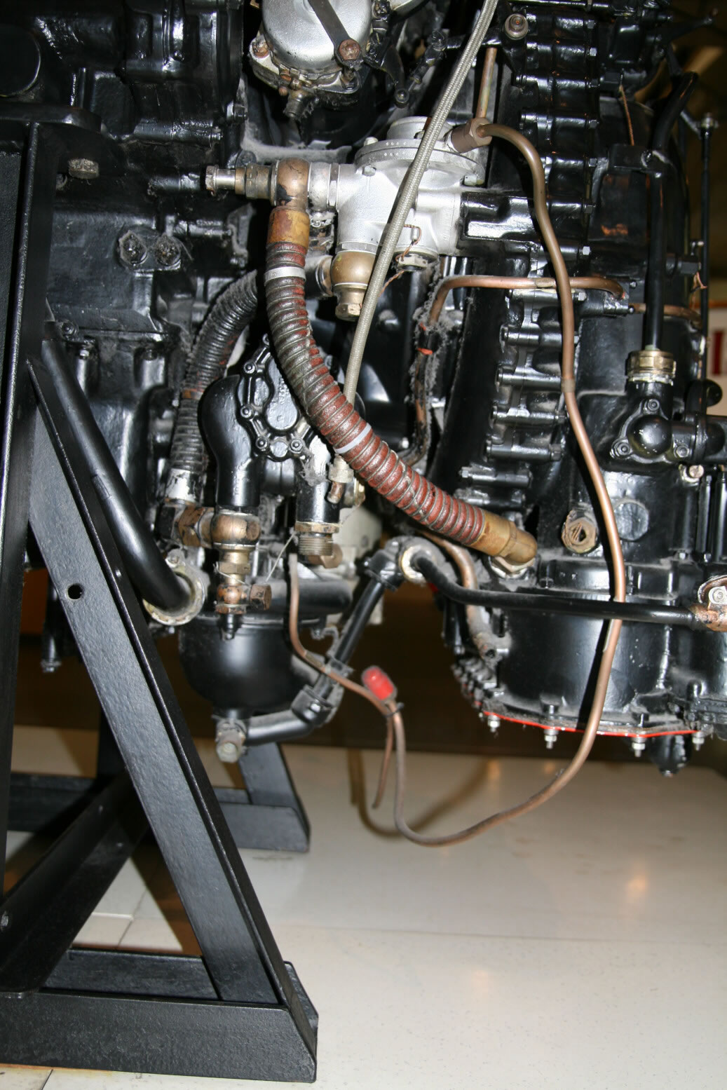
Photo 5 is roughly the bottom part of photo 4 but seen a bit from below. At the very bottom is the coolant pump, with the black pipe (following the engine support) coming from that. There is a similar pipe on the other side. The fuel pump and bottom of the carburettor are well visible.
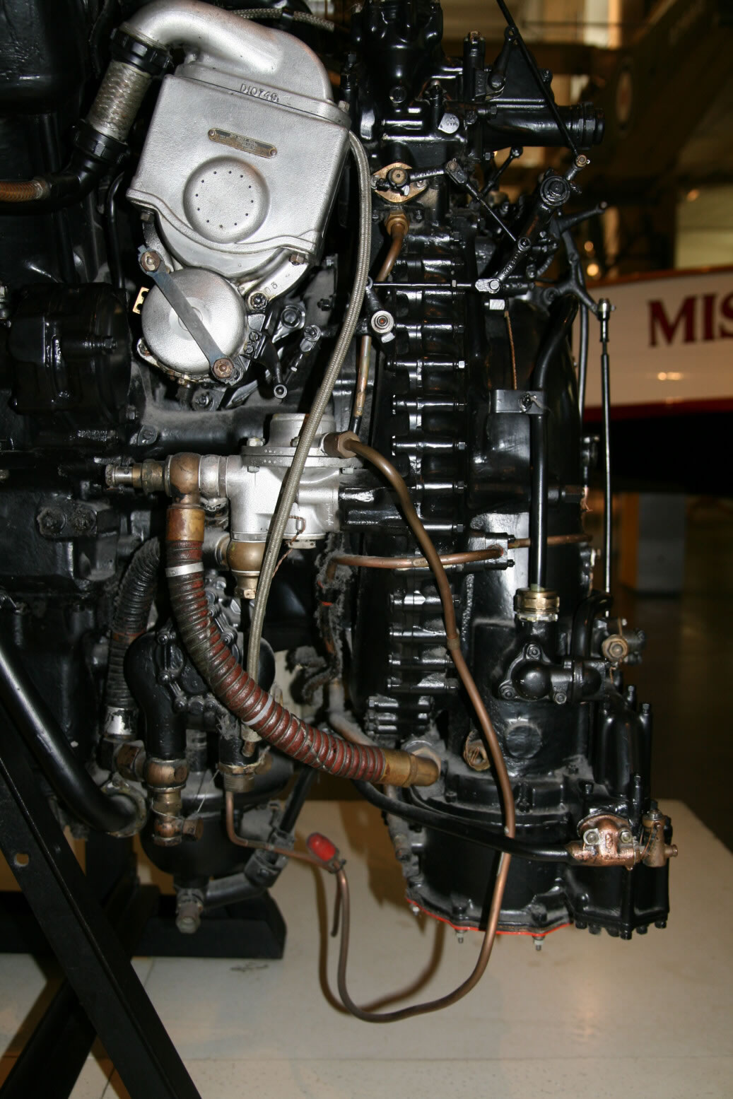
Photo 6 is another shot of the same area.
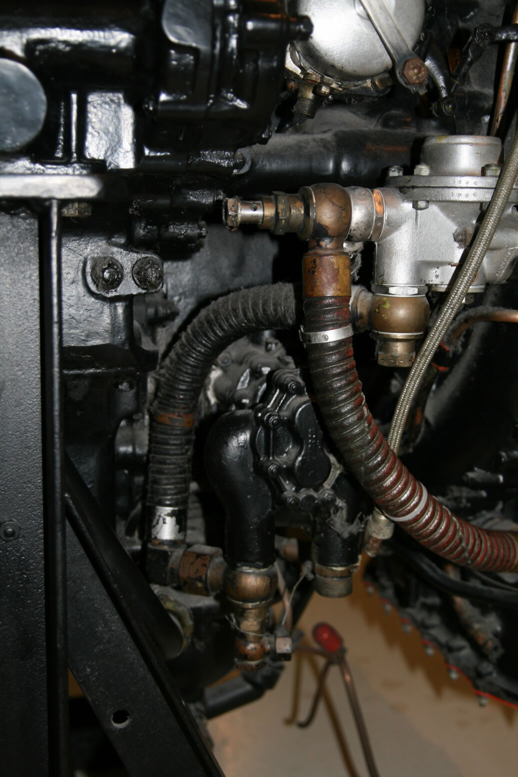
Photo 7 shows the fuel pump. The inlet pipe from the fuel tanks would enter on the right-hand bottom side, while the outlet is on the left.
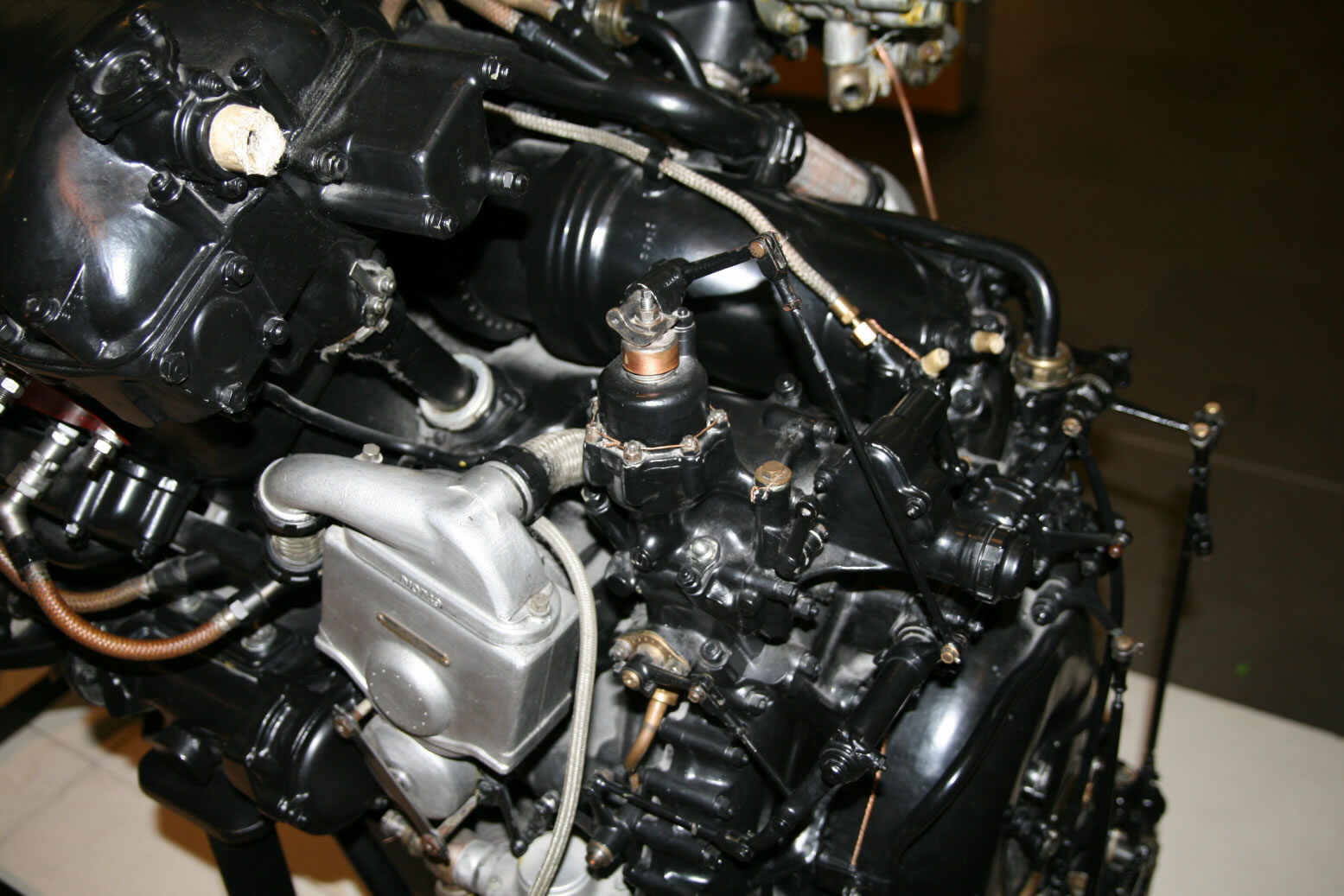
Photo 8 is shows the area above the port magneto from the top left. The unit in the center is the boost control. Note the rods connecting to the lay shaft. Also well visible is the cable connection of the magneto that runs to the starboard side, as well as the cam shaft drive housing going down from underneath the cam shaft cover. The big pipe directly behind the boost control unit is the outlet from the supercharger that goes between the two cylinder banks. The strange light-colored plug (paper, wood?) top left is where the engine tachometer drive Bowden cable would be connected. That cable enters the fire wall behind the engine just above the port top engine bearer and from there goes on to the instrument panel.
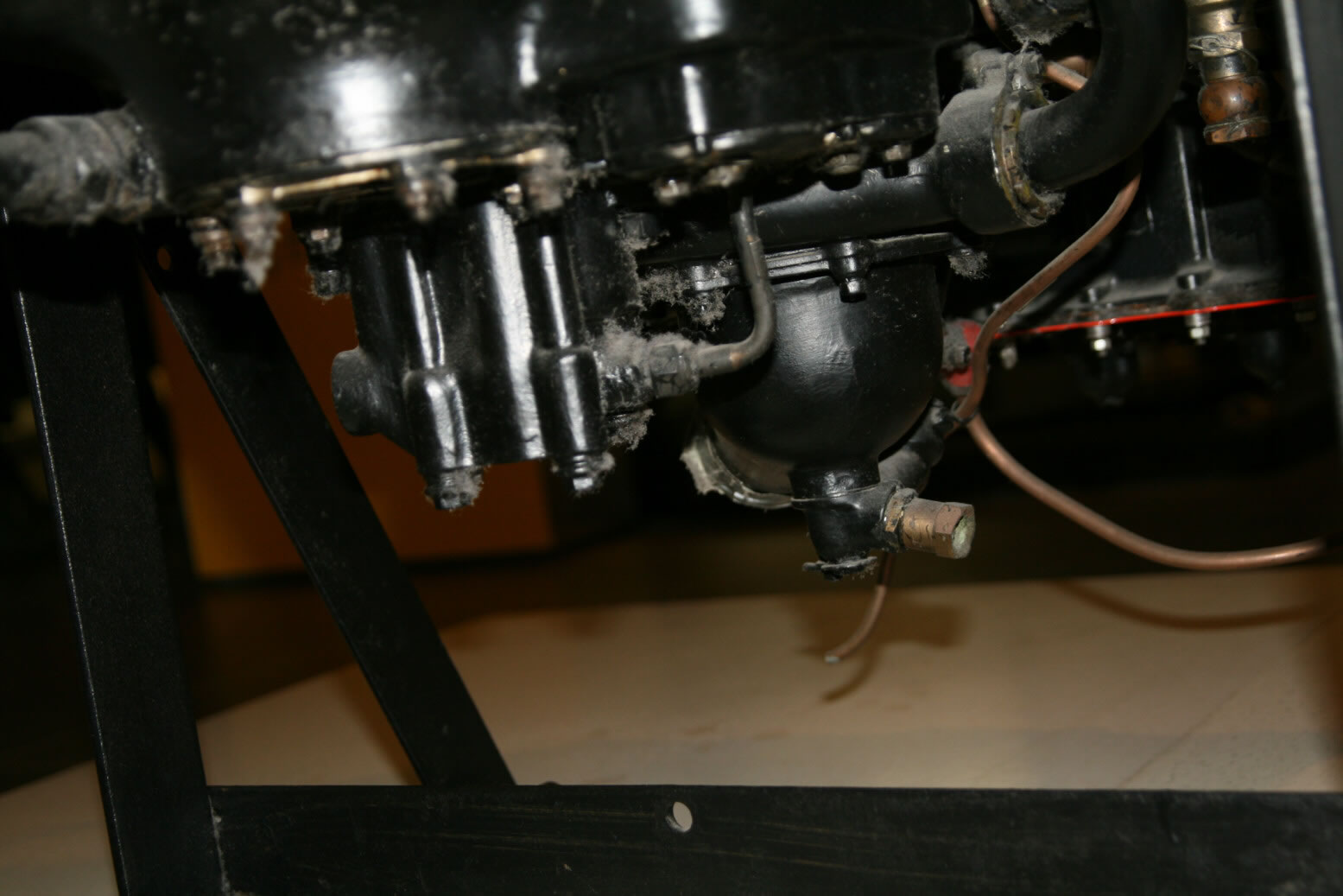
Photo 9 shows the bottom with the coolant pump on the right and the oil pump on the left.
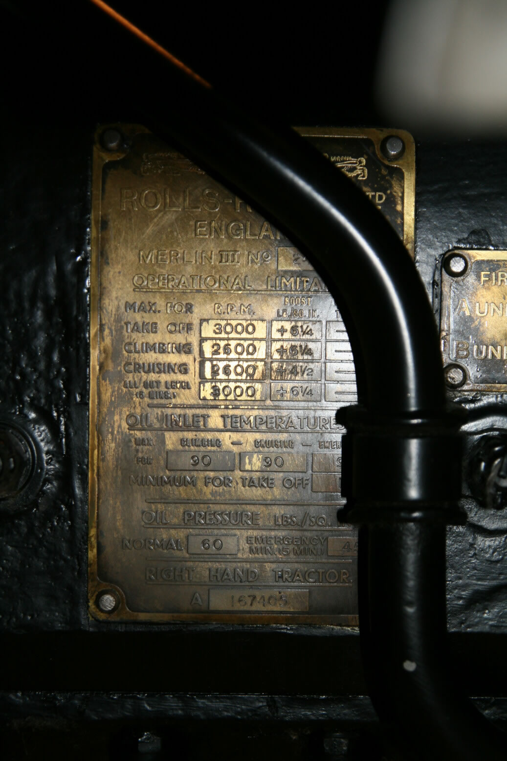
Photo 10 is a detail shot of the engine data plate.
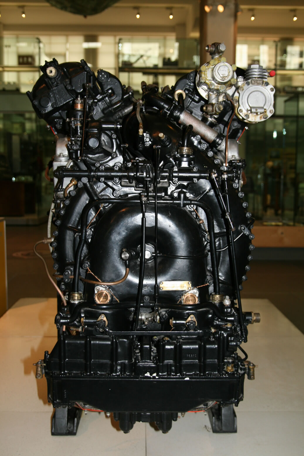
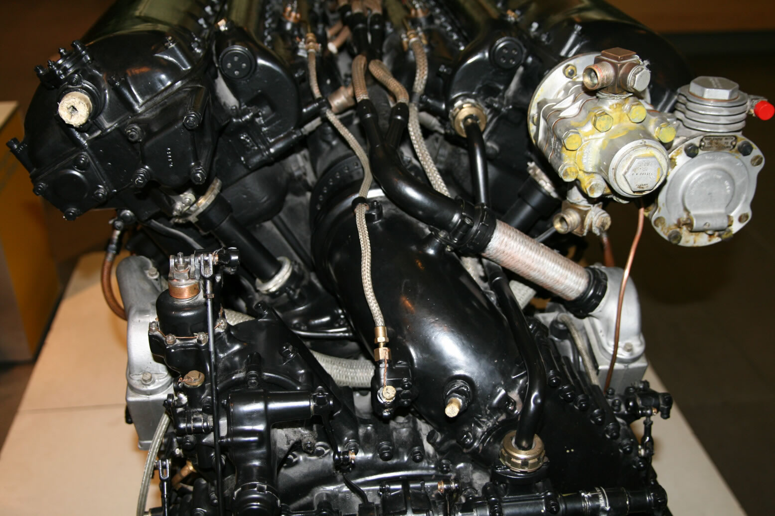
Photo 11 shows the back of the engine. At the top, on the back of the starboard cam shaft cover are the compressor (furthest to the right) and the hydraulics pump. The former is connected towards the fire wall at the back through a thin pipe with loops (to take the slack), while the hydraulics pump has its inlet/outlet at top and bottom, also connecting to the structures on the fire wall. The horizontal shaft is the engine control lay shaft. This is connected by rods to a similar shaft on the firewall. That shaft is again connected to the engine controls in the cockpit (throttle, etc.).
Photos 12 and 13 cover the same area, but from towards the right and left.
Photo 14 shows the area with the fuel pump and carburettor a bit from the back in more detail.
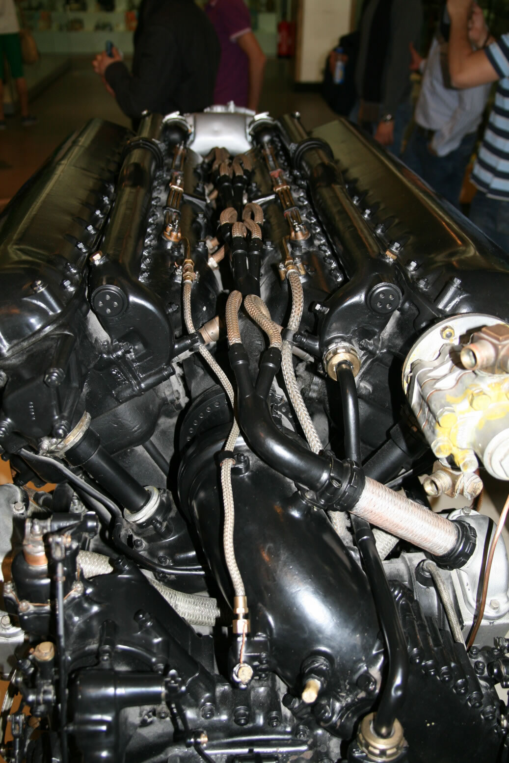
Photos 15 and 16 show the backside detail more from the top. This view clearly shows that the area at the top between the cylinder banks is not solid but hollow. This is where the big pipe from the supercharger spiral goes in (note that it is a spiral, not just a bent pipe, going from vertical to horizontal in line with the engine). The cable connection of the starboard magneto is well visible, running to the inner spark plugs on both sides. Also note the cam shaft drives tilted at roughly the same angle as the cylinder banks.
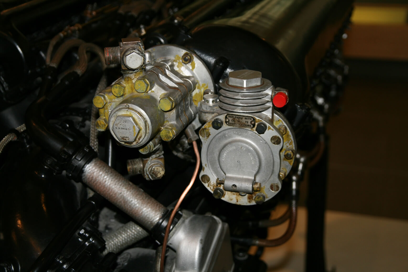
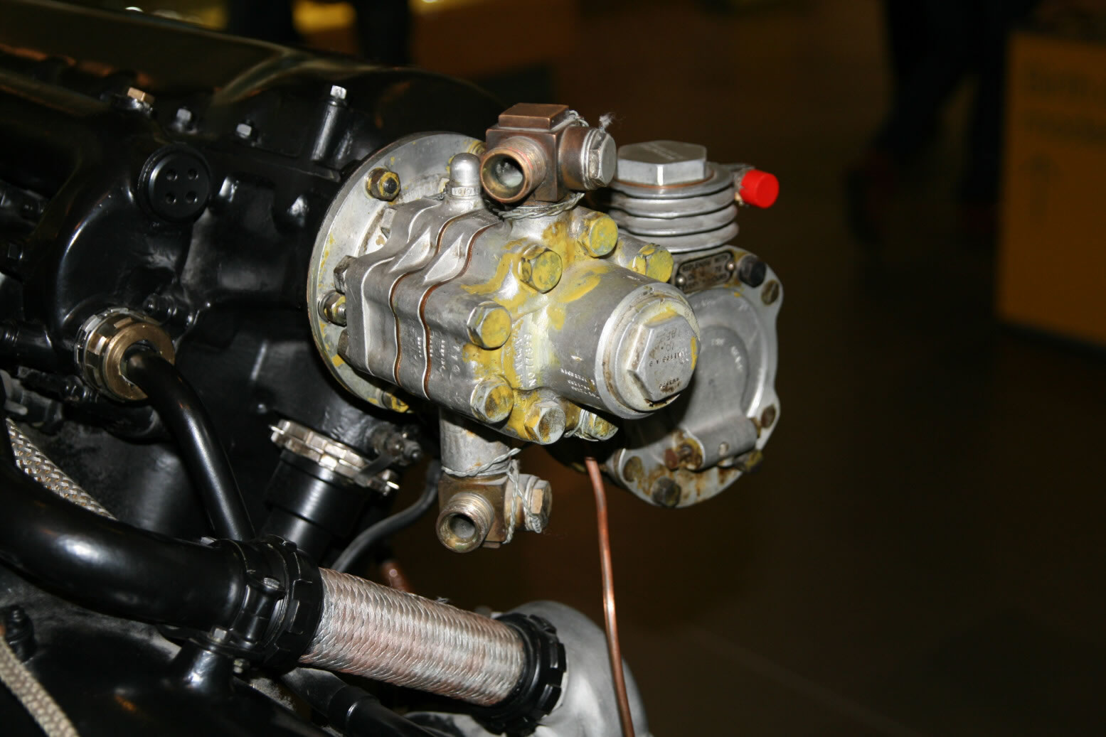
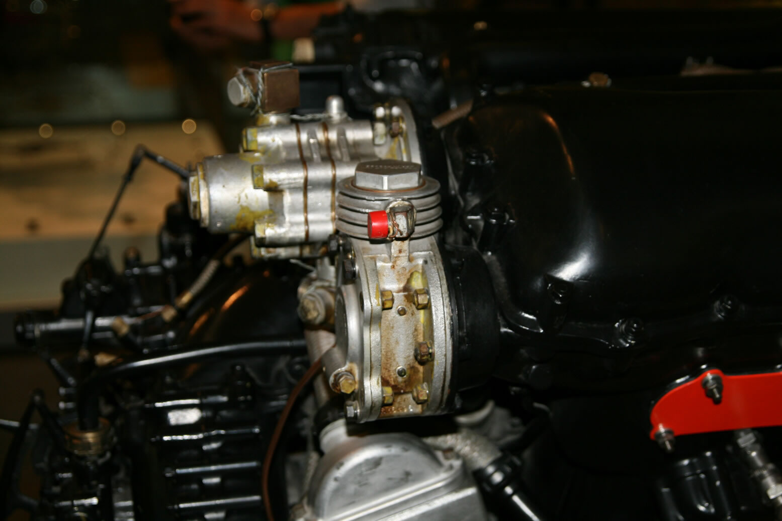
Photos 17 through 19 show the hydraulics pump (left) and compressor. In general you can assume that any thin pipe is an oil connection for lubricating the ancillary equipment.
Going on to the starboard side, photo 20 isn't as sharp as it should be but it's the only one with a full view. On the side of the engine is a collection of oil lines that connect to a unit that has the oil gauge. Beneath the starboard magneto (note how different its cable connection is to that of the port one) is the starter engine. The two bolts/nuts placed vertically on its lower part are where the electrical wiring connects that comes from the starter plug outlet on the outside of the aircraft.
Note that this side of the engine is quite the same for all marks, the most conspicuous difference being the color of the magneto housing (but that varies even within the same mark).
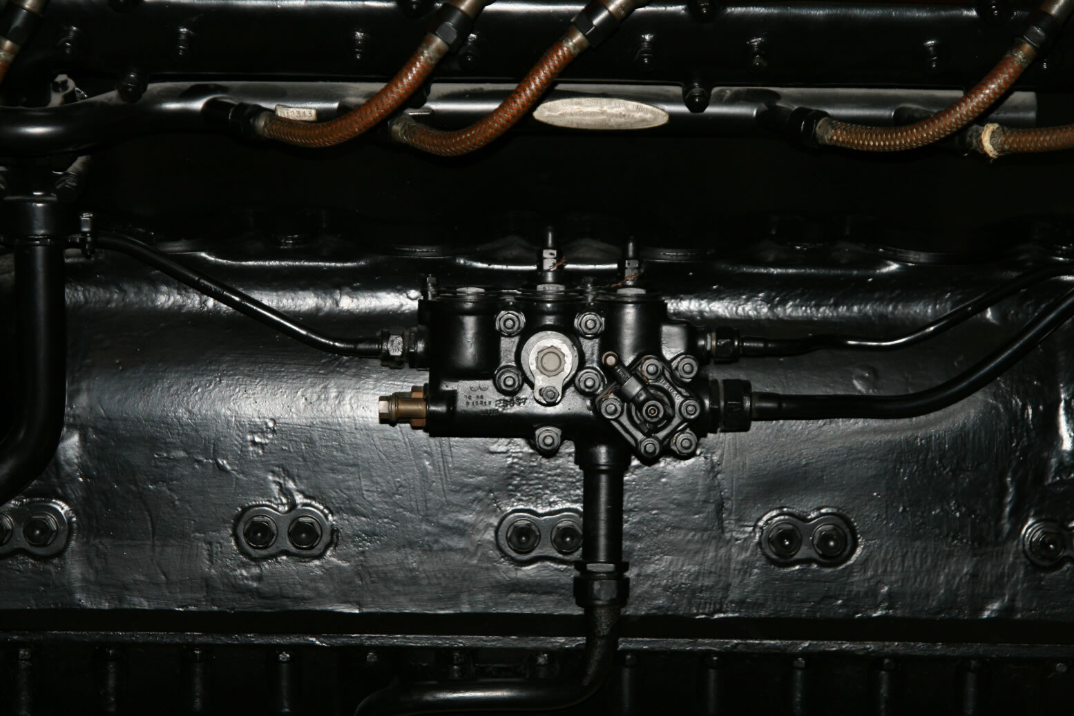
Photo 21 is a detail show of the oil pipes and gauge.
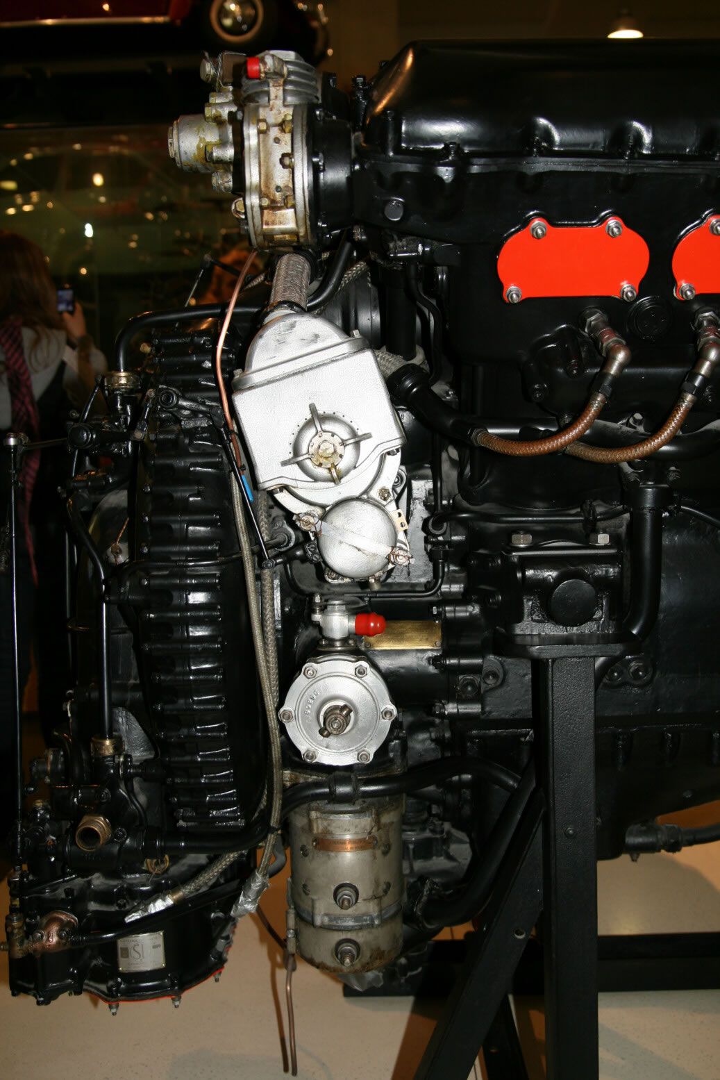
Photo 22 is a detail shot of the magneto and starter engine.
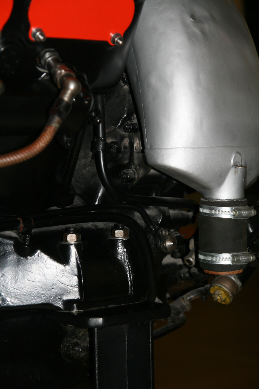
Photo 23 shows detail at the front of the engine. You see the front-most ignition cable, coolant header tank and some detail further behind it.
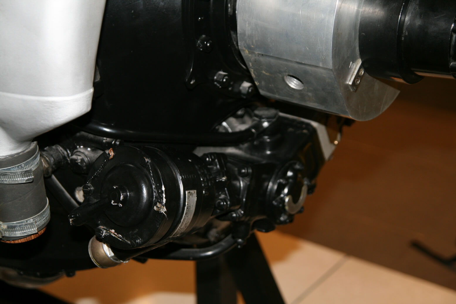
Photo 24 shows part of the airscrew constant speed unit at the front of the airscrew reduction gear.
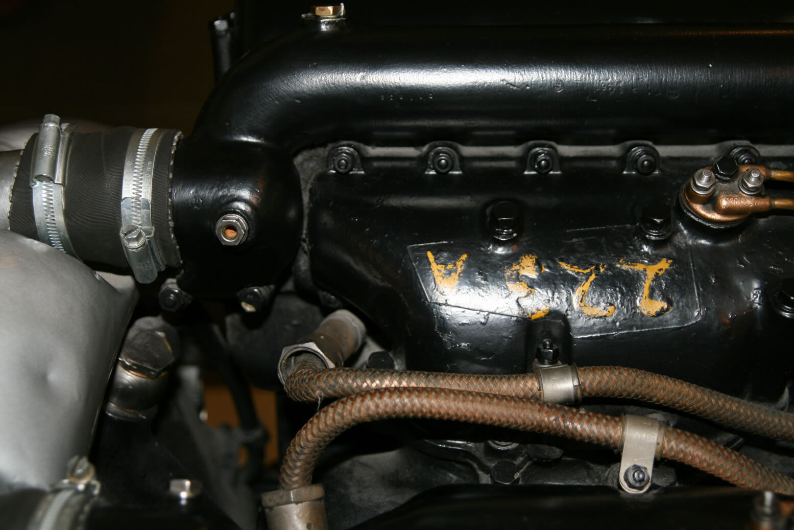
Photo 25 shows a top view near the front of the engine, with the connection between the engine and the coolant header tank (the hose with the two clamps). The one visible is the starboard one, there is another one on the port side. The braided-wire cables are the ignition cables of the two front-most inner spark plugs.
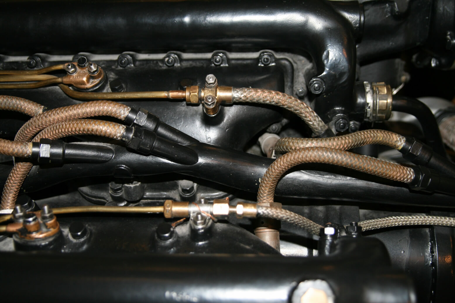
Photo 26 is also from the top but now the back end. Some of the braided cables are ignition wiring (the ones horizontally in the center) from the starboard magneto. The other two (top and bottom) are oil lines.
Photos 27 and 28 show the boost control unit. Especially in photo 28 you can see how it is connected to the lay shaft at the back of the supercharger housing. This lay shaft is connected to a similar lay shaft on the firewall of the aircraft by several rods which transmit the controls from the cockpit into actions on the engine. Regrettably you never see the connections between the two lay shafts in reference material. Either the engine is removed from the aircraft and the connections are not there or the engine is in place and it blocks the view.
Merlin III, RAF Museum
This particular engine is a bit different from the one in the Science Museum. A lot of the ancillary equipment is missing. Its starboard side is not accessible as that is on a no-walk area in the museum.
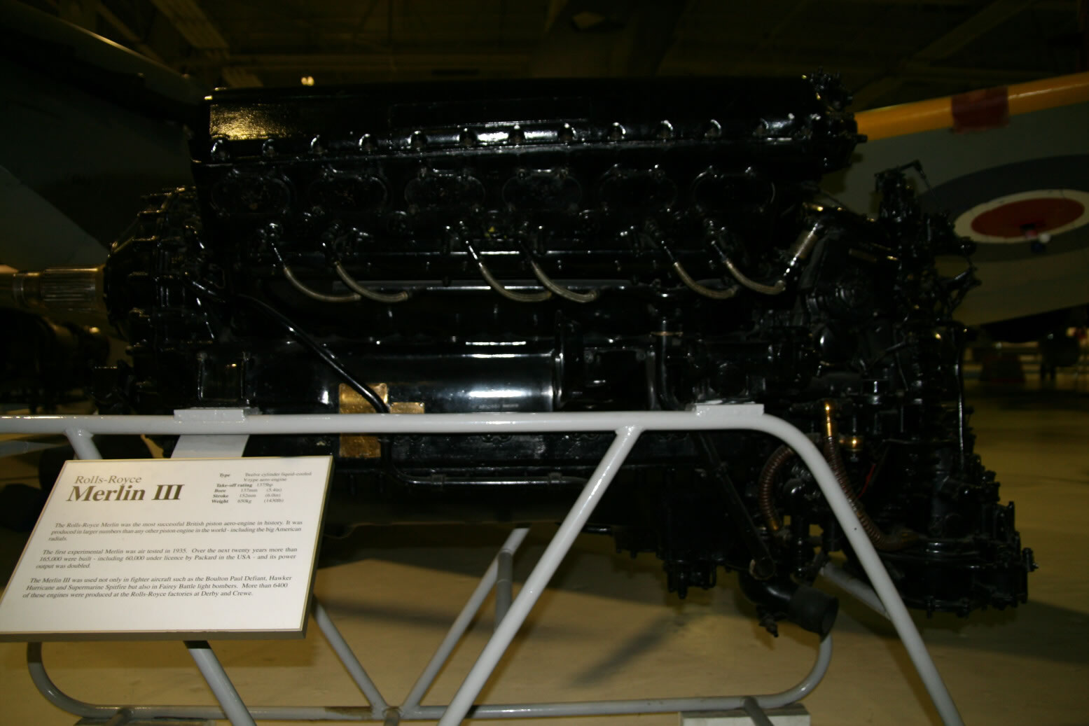
Photo 29 shows the port side view of the engine.
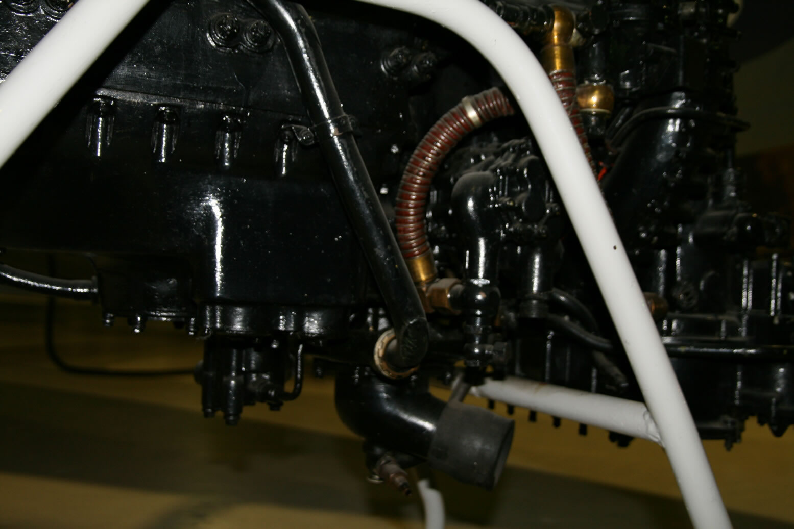
Photo 30 shows the bottom of the engine with the oil pump and coolant pump. The big pipe at the bottom is the coolant connection to the radiator.
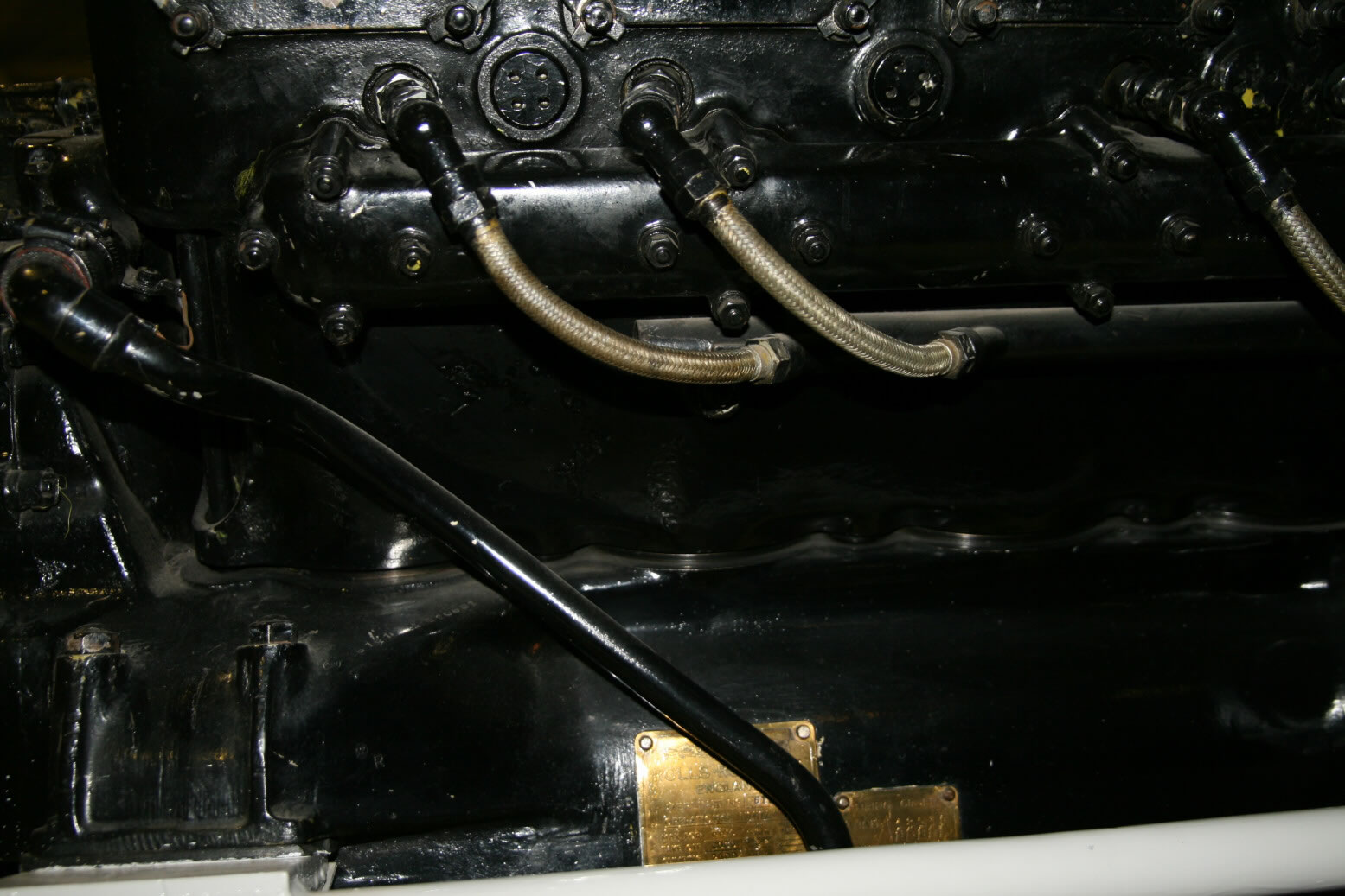
Photo 31 shows the front of the port engine side with a pipe whose purpose is unknown (to me; in view of its thickness it probably is a coolant pipe) plus the cylinder sidewall and spark plugs.
Photo 32 through 35 are all from the top of the engine, seen from the port side.
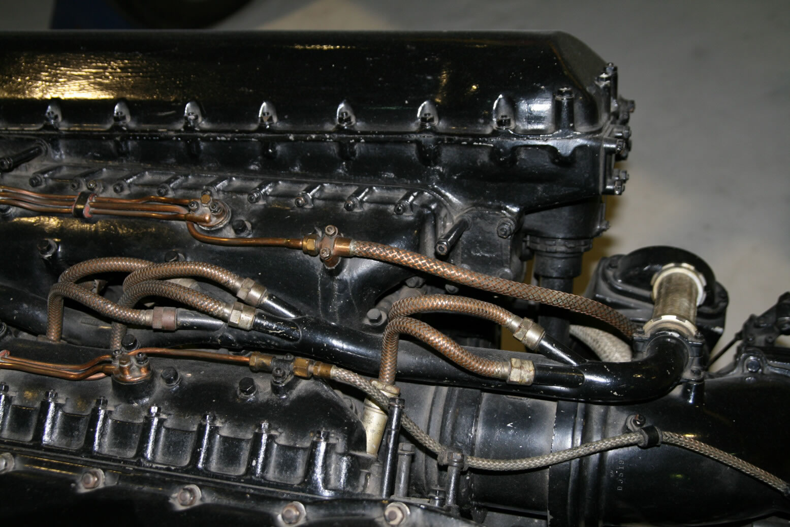
Photo 32 shows the back end with two braided oil lines (towards top and bottom) and between the ignition wiring for the inner spark plugs.
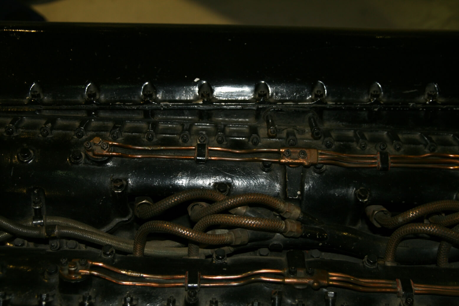
Photo 33 shows the part in front of photo 4, again with the (now thin) oil pipes and the braided ignition wiring.
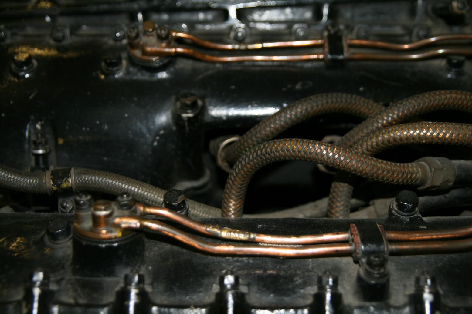
Photo 34 is a closer look at the ignition wiring.
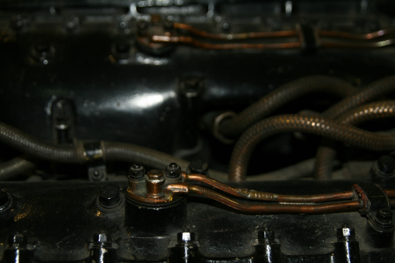
Photo 35 is a closer look at the oil pipes.
Photos 36 through 38 show the front of the top of the engine.
Photo 36 shows the front-most part. At the bottom is the top rim of the air screw reduction gear. The rounded part above it that looks like the top of a gas cylinder, is the front part of the pipe coming from the supercharger. The two spark plugs are the front-most inner ones.
Photo 37 shows the same area a bit from the port side.
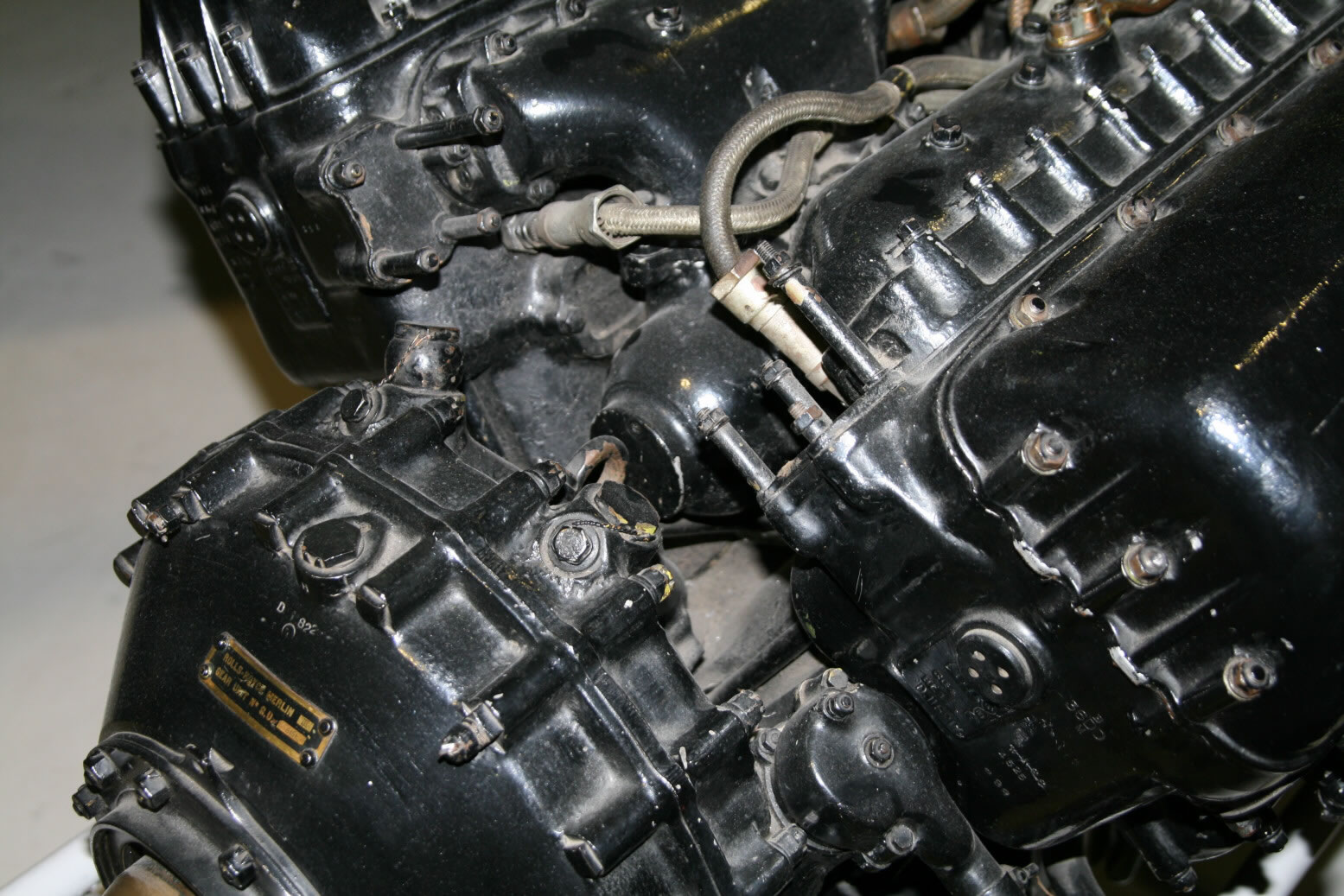
Photo 38 has the same area but zoomed out.
Photos 39 and 40 show the backside of the supercharger. Note the many oil and coolant pipes.
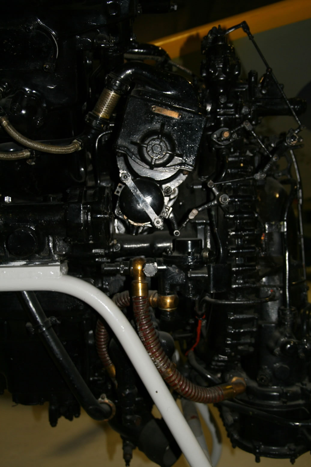
Photo 41 shows the port side of the supercharger with the port magneto and probably is the carburettor (the uncertainty stemming from the fact that it differs from later Merlin engines where the carburettor is mounted on the front bottom of the air intake, while no such part is present on the Merlin III, but I have no reference material with positive identification). The fuel pump is largely hidden by the support of the engine.
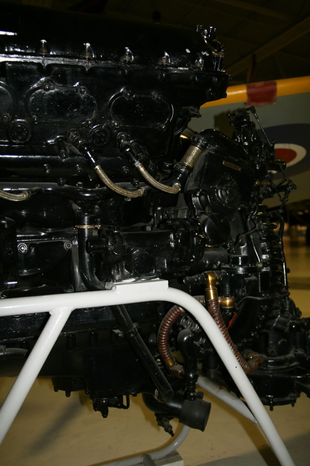
Photo 42 show the same but more from the front.
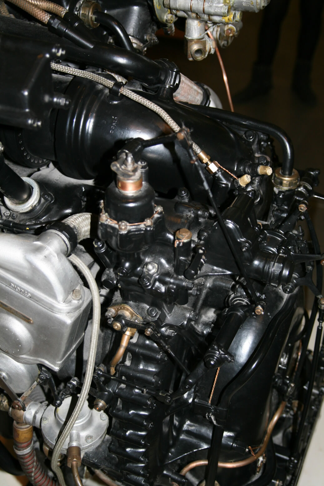
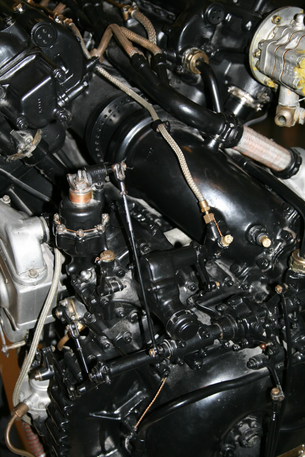
Photos 43 through 45 show the top of the back end of the engine.
At the bottom of photo 43 the engine control lay shaft is well visible with its multitude of rod connections, to the advances of the magnetos (extreme right and left) and the boost control unit (rod going up about 1/10th from the left). There are also two control rods going down vertically at the center back, presumably to the throttle controls. Well visible is the spiral from the supercharger with the big pipe going forward between the cylinder banks.
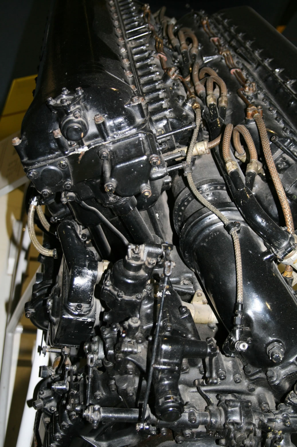
Photo 44 shows a more detailed view with the boost control unit slightly below the center.
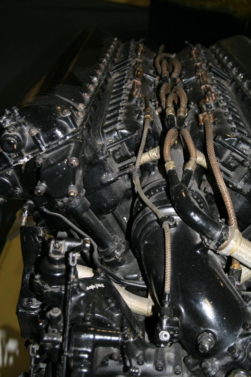
Photo 45 gives another view with the cam shaft drive rod housing for the port cylinder bank well visible.
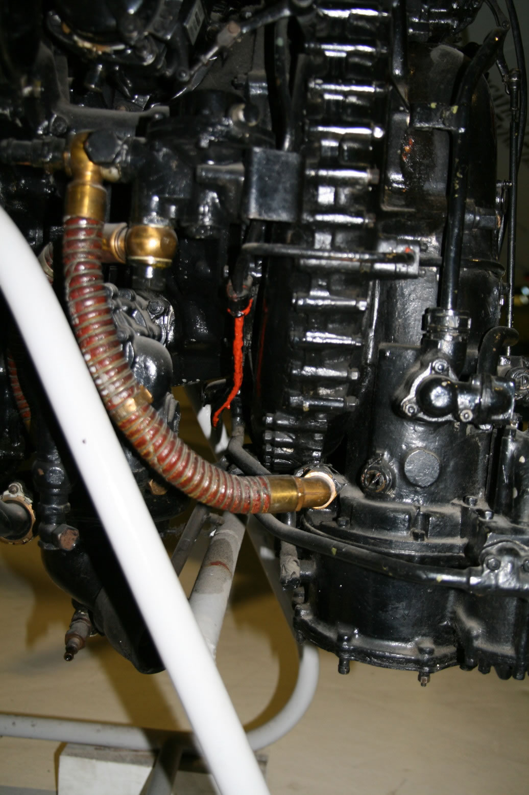
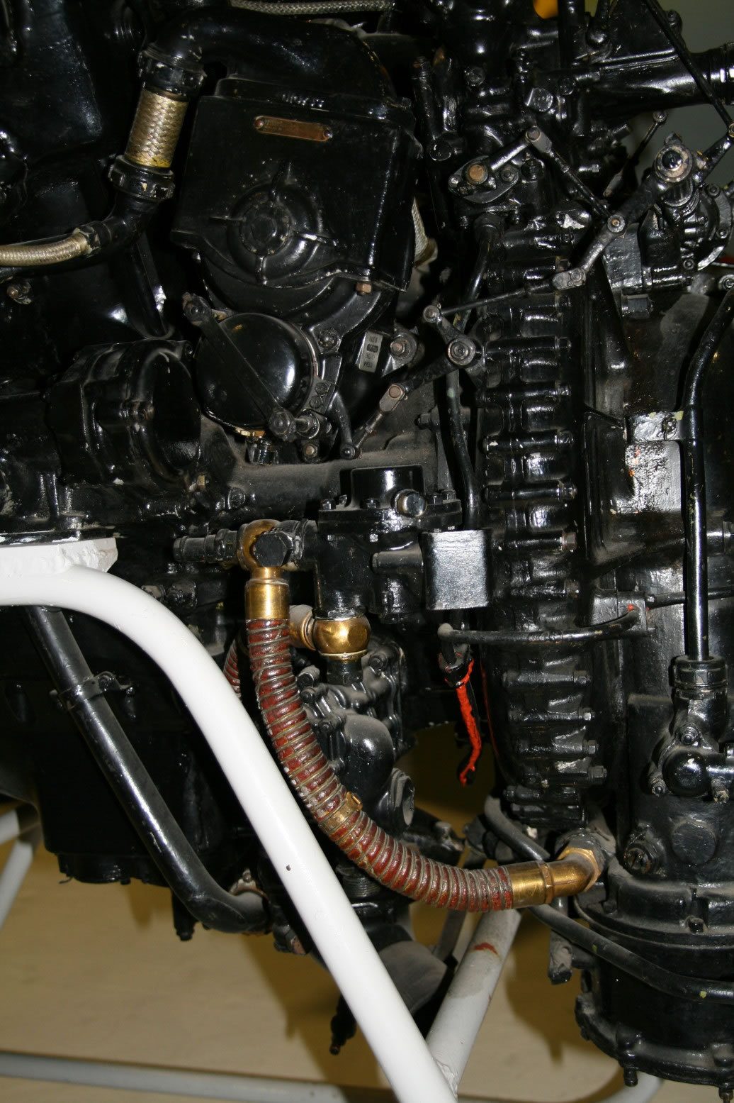
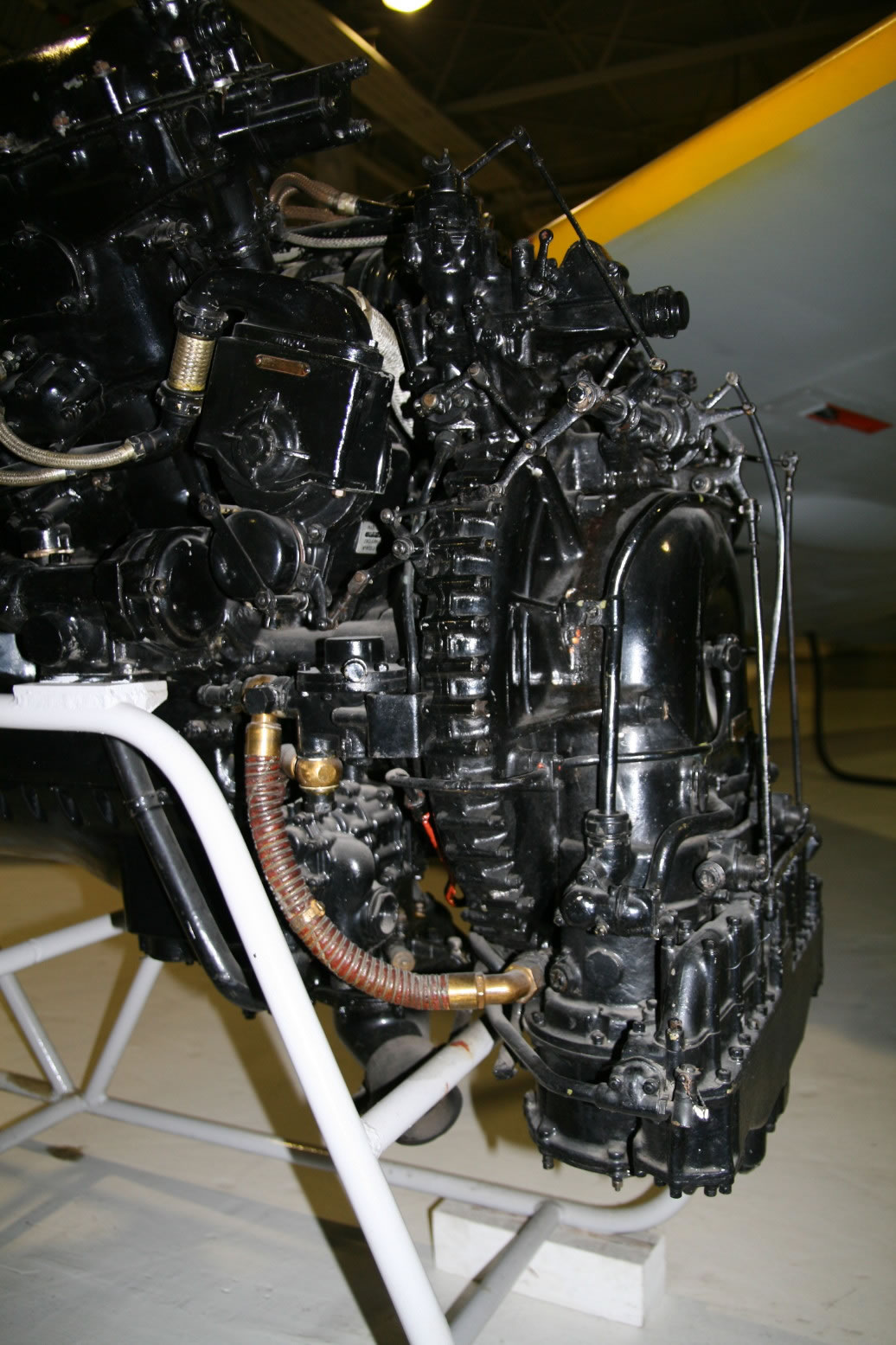
Photo 46 through 48 show the ribbed fuel pipe coming from the carburettor.
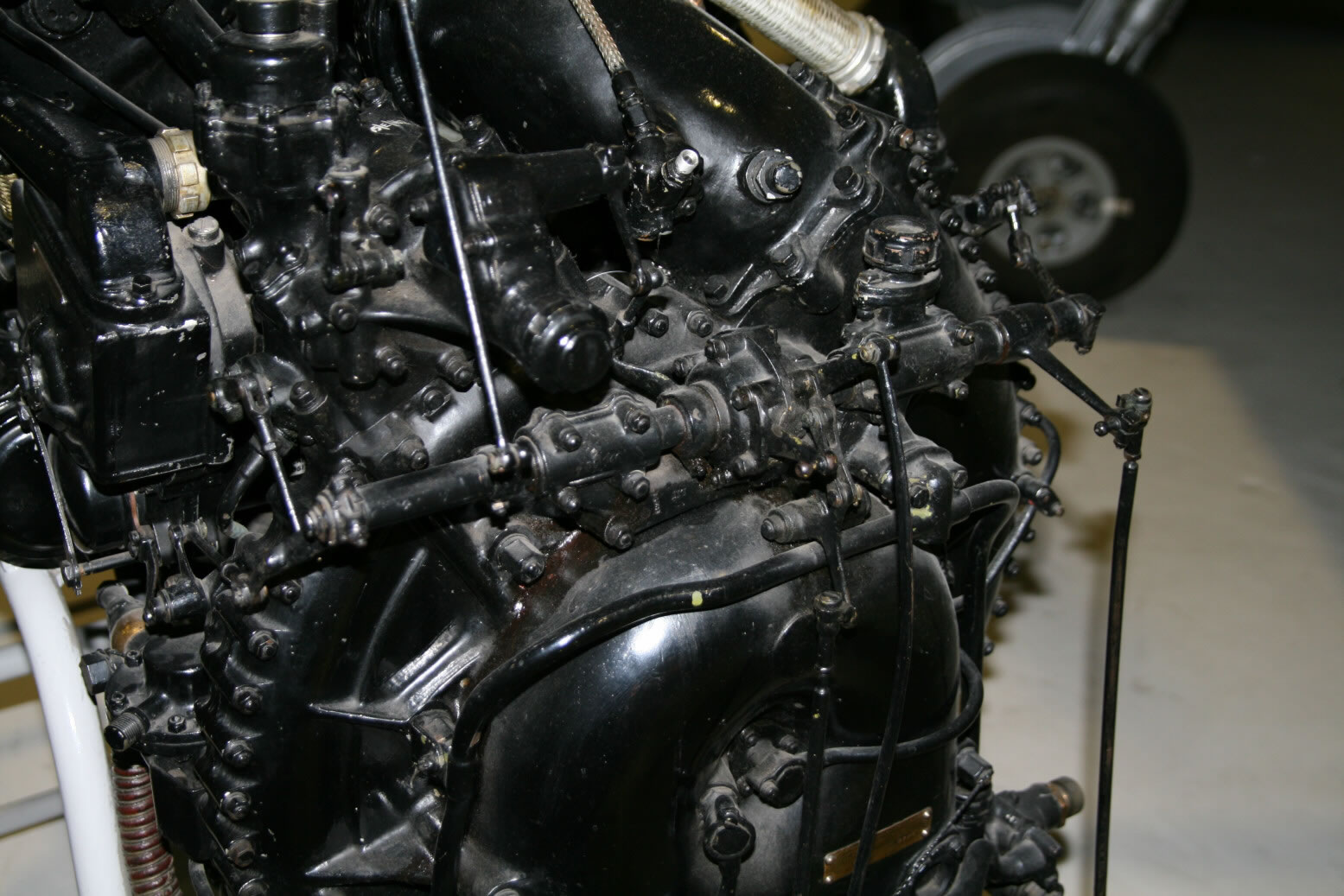
Photo 49 shows the engine control lay shaft in detail.
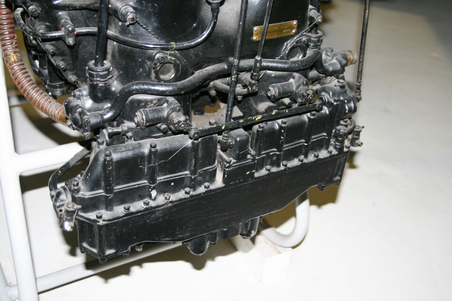
Photo 50 shows the bottom of the supercharger with the air intake (air coming from below).
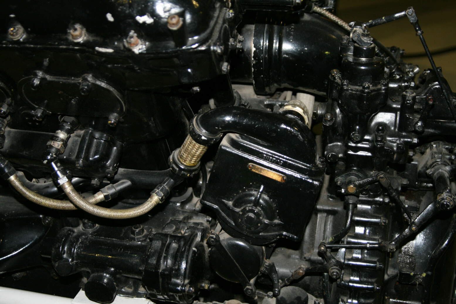
Photo 51 shows the port magneto.
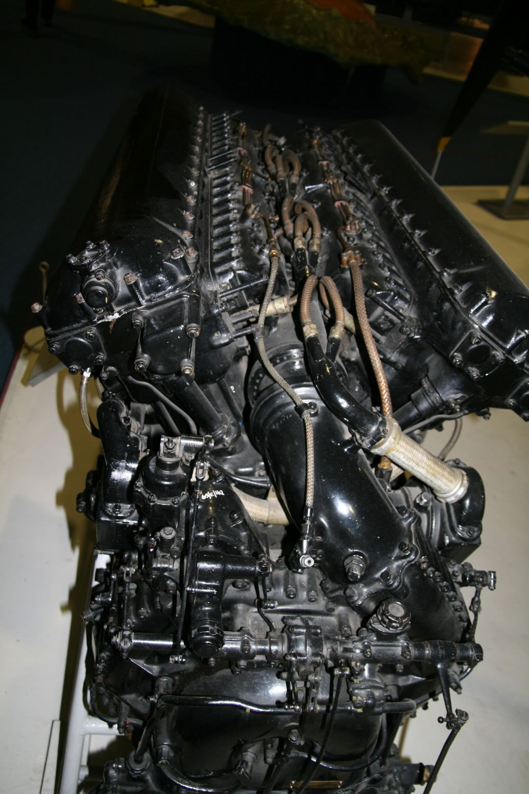
Merlin III, RAF Museum, Hurricane Wreck
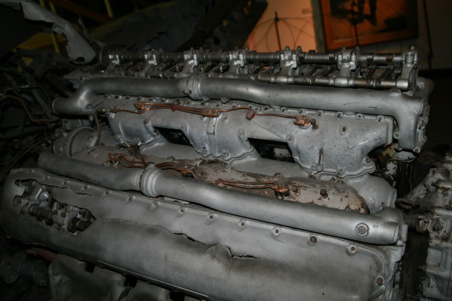
A very short walk around, but well worth it (I think) as it so clearly displays the structure of the top of the Merlin engine. The photo (52) is from the Merlin of the Hurricane wreck. The front of the engine is to the right. The cam shaft cover at the top of the photo is missing, while the one at the bottom is bent and fractured. But what I find really interesting is the way it clearly shows the shape of the coolant pipes (next to the cam shafts) and the fuel inlet system. At the front the coolant pipes would connect with two connecting pipes to the coolant header tank. The fuel inlet system consists of a big pipe coming from the supercharger at the back (it is the pipe below the rectangular gaps which is where the spark plugs are). Mounted on top of that is an M-shaped, bulging unit (with the copper oil lines on top) which is the feed to the cylinders.
© Max Otten 2013
This article created on Thursday, January 16 2014; Last modified on Thursday, March 31 2016