
Napier Sabre
Photos By Max Otten
The photos were taken at the Science Museum, Imperial War Museum, and RAF Museum Hendon (all in London, England).
During the war there were three engines developed that you can consider double 'standard' engines, with cylinder banks above and below a shared crank shaft (or shafts). These were the Napier Sabre, Rolls-Royce Vulture (both United Kingdom) and the Daimler-Benz 606 (Germany). All were in essence failures.
The Rolls-Royce Vulture powered the Manchester bomber. After acknowledging that the engine would never be any good, AVRO had the good sense to suggest a four-engined (mostly Merlin) variant of the Manchester, which became the unequalled Lancaster bomber.
The Daimler-Benz 606 powered the Heinkel 177 Greif bomber. One reason for having the two 606 engines instead of four of the reliable 601's was the incredibly dumb specification that the Heinkel 177 should be suitable for dive bombing (a similar specification haunted the Junkers 88 bomber, causing development delays and unnecessary weight increases that reduced its performance). Dive bombing the Heinkel 177 would be prevented by the additional drag of two more propellers, so the choice fell on the 606. Like the Vulture it had endless cooling problems and could spontaneously burst in flames.
The Napier Sabre had its own share of problems. In the early stages Napier could not get the sleeve valves to work without a very high rate of failure. Typical engine failure rates would be of the order of a few tens of hours. It wasn't until the Bristol engineers gave a helping hand that Napier got the sleeve-valve problem under control. Still the engine had a very high failure rate and required a high degree of maintenance. The Coffman starter was underdimensioned for the heavy engine and starting problems were frequent. If the engine failed to start, it would backfire and flame would spout from the air inlet, making it necessary to have ground crew standing by (to the side!) with a fire extinguisher. Engines that would fail more than normally to start at first attempt were known as 'bitches'.
Still, the engine was used for the Hawker Typhoon and Tempest. Hawker also considered another engine, the radial Bristol Centaurus, but due to pressing war needs it was not available. The Hawker Typhoon, like its engine, had its own problems and were it not for the war, would never have flown on duty. There was a persistent, unsolvable carbon-monoxide leak from the engine, forcing the pilots to fly with oxygen masks on all the time, and it also could shed its tail due to elevator flutter, a problem that was only really solved with its successor, the Tempest. It also failed as a high-altitude interceptor with its poor rate of climb. But it did well 'on the deck', intercepting Fw 190 'nuisance' raids. And finally it came into its own, the ground-attack role, with bombs and ultimately the rockets that terrified the German ground forces. After the war the United Kingdom couldn't get rid of its Typhoons and Napier Sabres fast enough and it is noticeable that the later Tempest II and its marine development, the Sea Fury, used the Bristol Centaurus engine.
The engines in the Science Museum, London, are mostly displayed in racks two levels high. On the back side (inaccessible) is a window with a very light wall behind it. The sun shone on the wall, making picture taking far from easy. Also, the Sabre is displayed at the second level and a great deal of its top is obscured by an aircraft that blocks the view from the upper gallery. The engine itself has been cut open in various places so if you see a gap that makes no sense (especially if there is a red, blue or beige color behind), it doesn't belong there. Still, the engine shows the underside quite well.
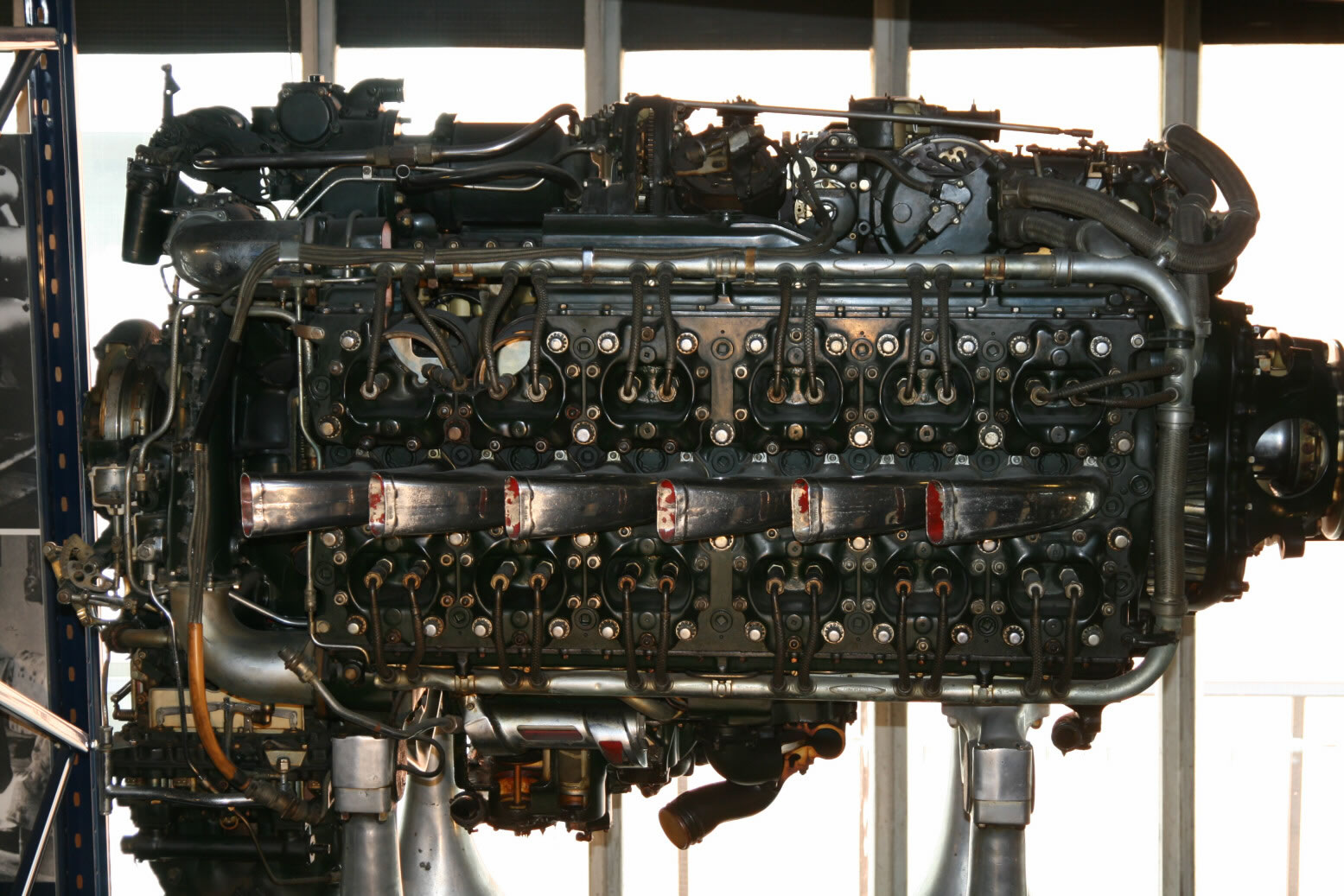
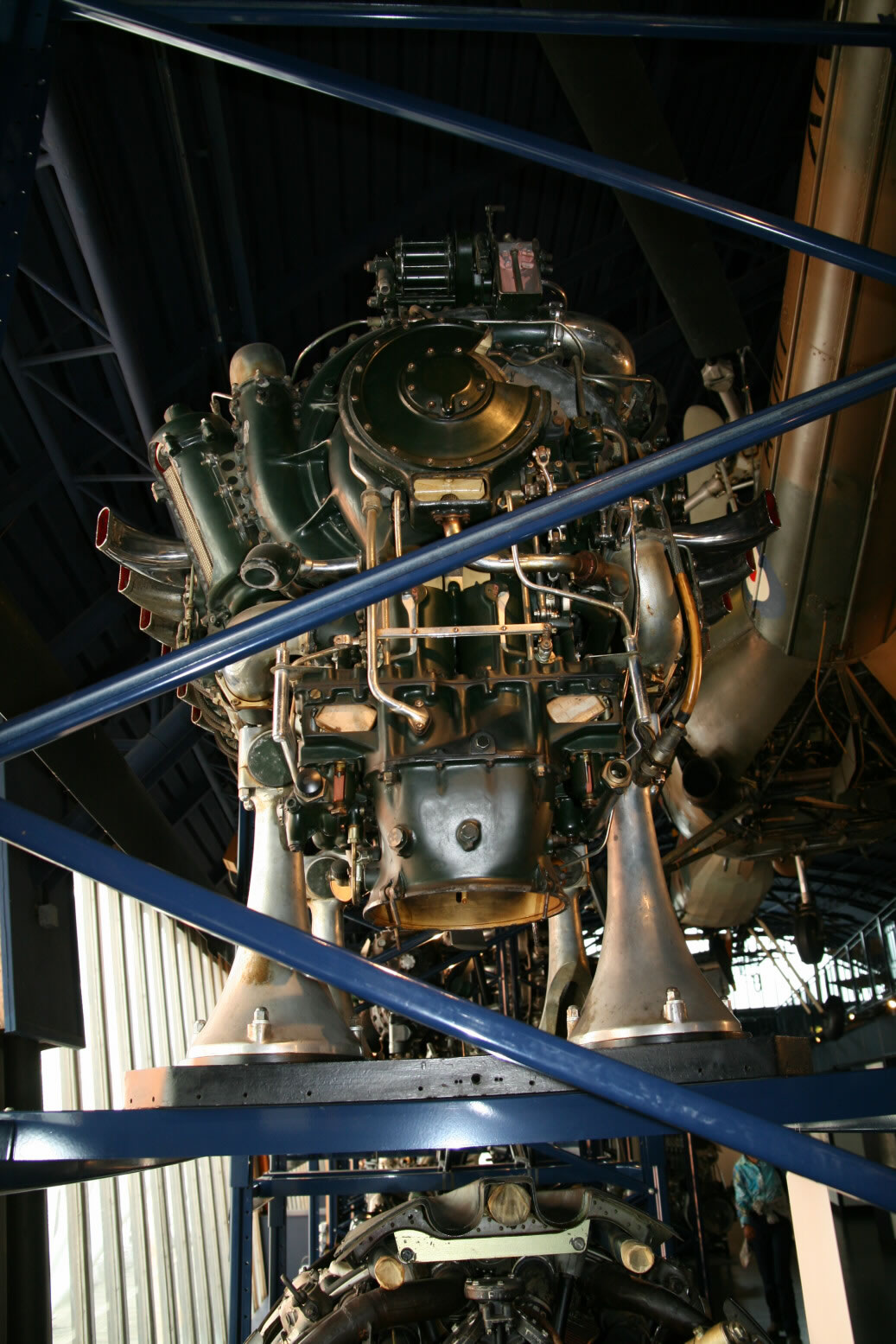
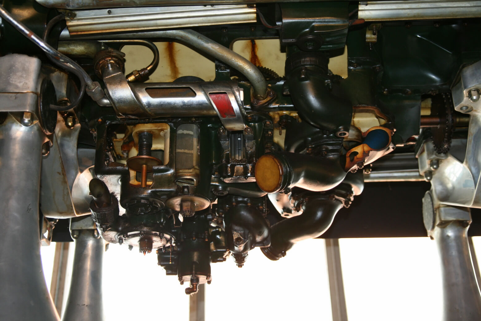
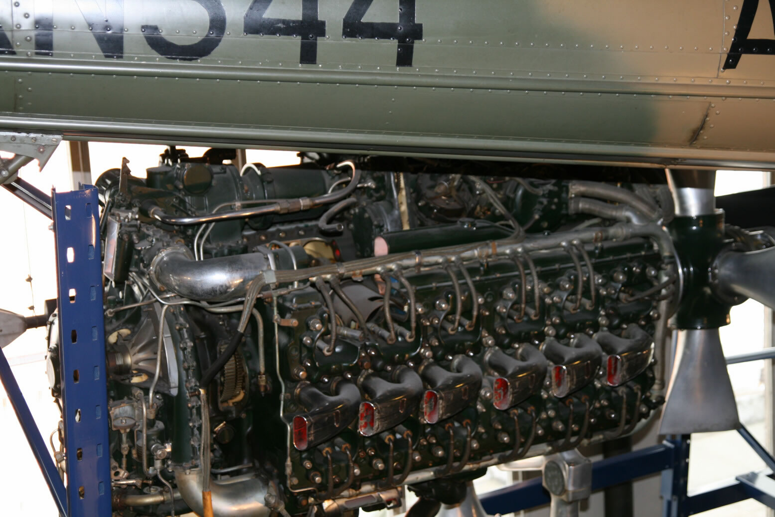
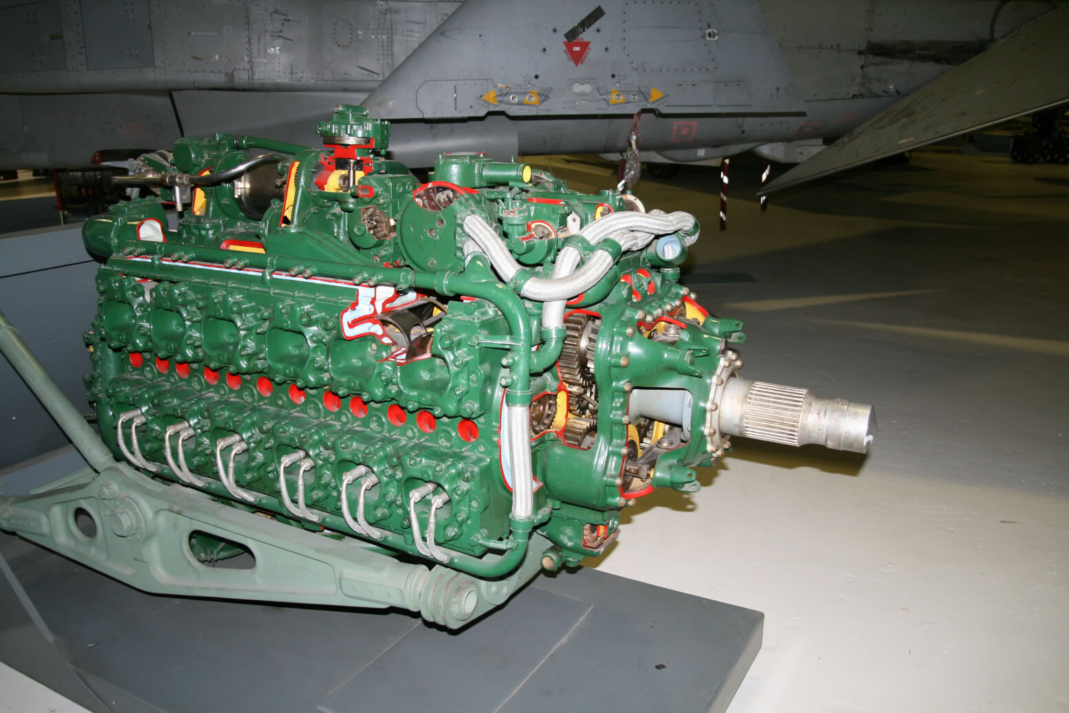
Photo 1 shows a starboard side view of the engine, with its front to the right. You can see the sides of the six top and six bottom cylinders (the engine layout is in an 'H' shape with the cylinders on each side sharing a crank shaft). Each cylinder has two spark plugs, located next to each other on the outside. The metal pipe going around contains the ignition wiring. Note that the two hindmost top cylinders have been cut open, hence the strange light-colored metal parts there.
The supercharger is at the back, where it is much more integrated into the main part of the engine than for example with the Rolls-Royce Merlin. At the bottom of the supercharger is the air intake. Underneath the engine are the fuel, coolant and oil pumps. The fuel pump is on the port side so invisible in this view.
The round shape on top of the engine is a distributor. Above that is seen the crankcase breather unit. The engine is placed in a blue metal rack on four slightly conical supports. These are not part of the engine.
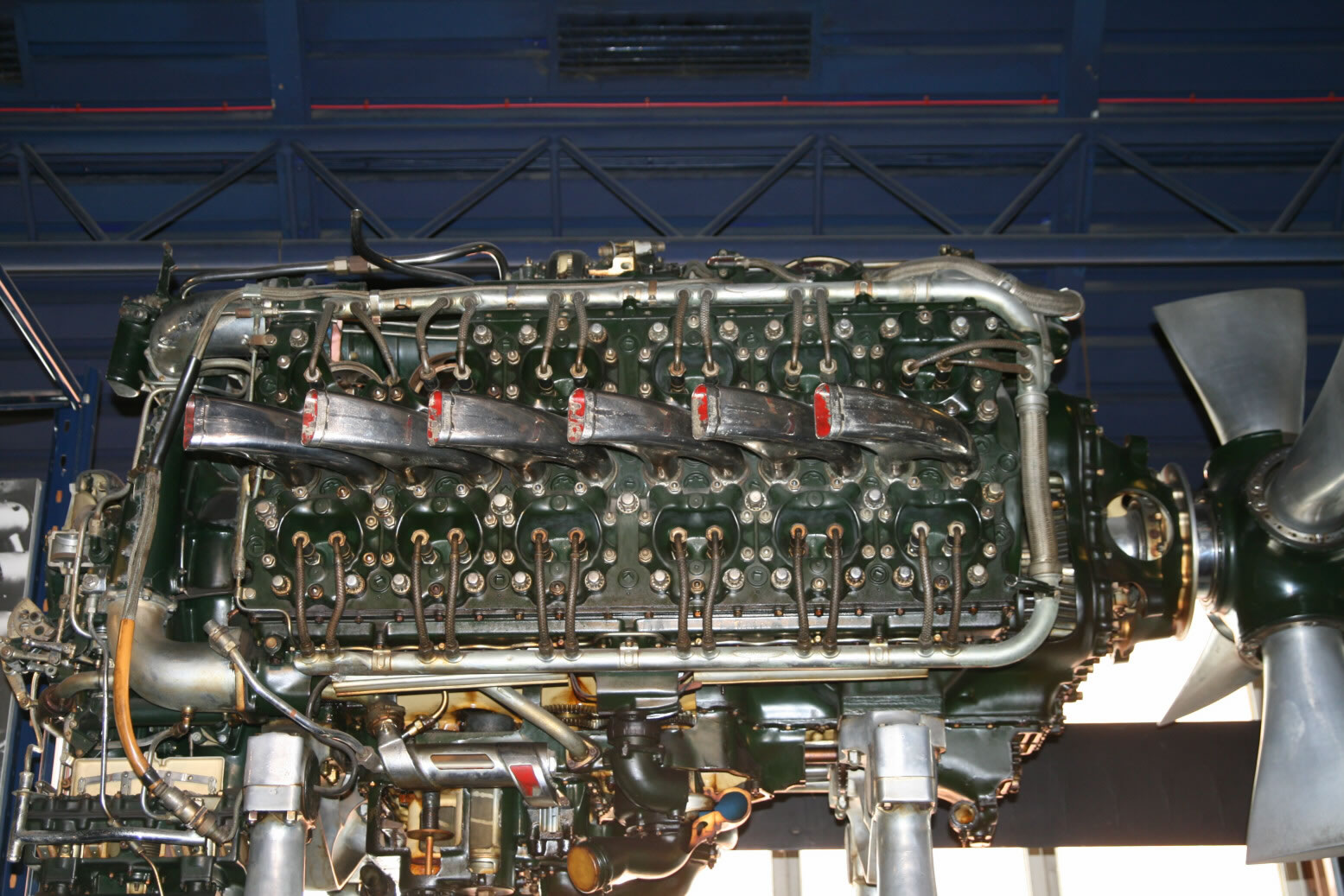
Photo 2 shows a view slightly from below. The propeller is seen in this photo as well (note that the blades have been cut off). There is a hole in the housing behind the propeller that is not original.
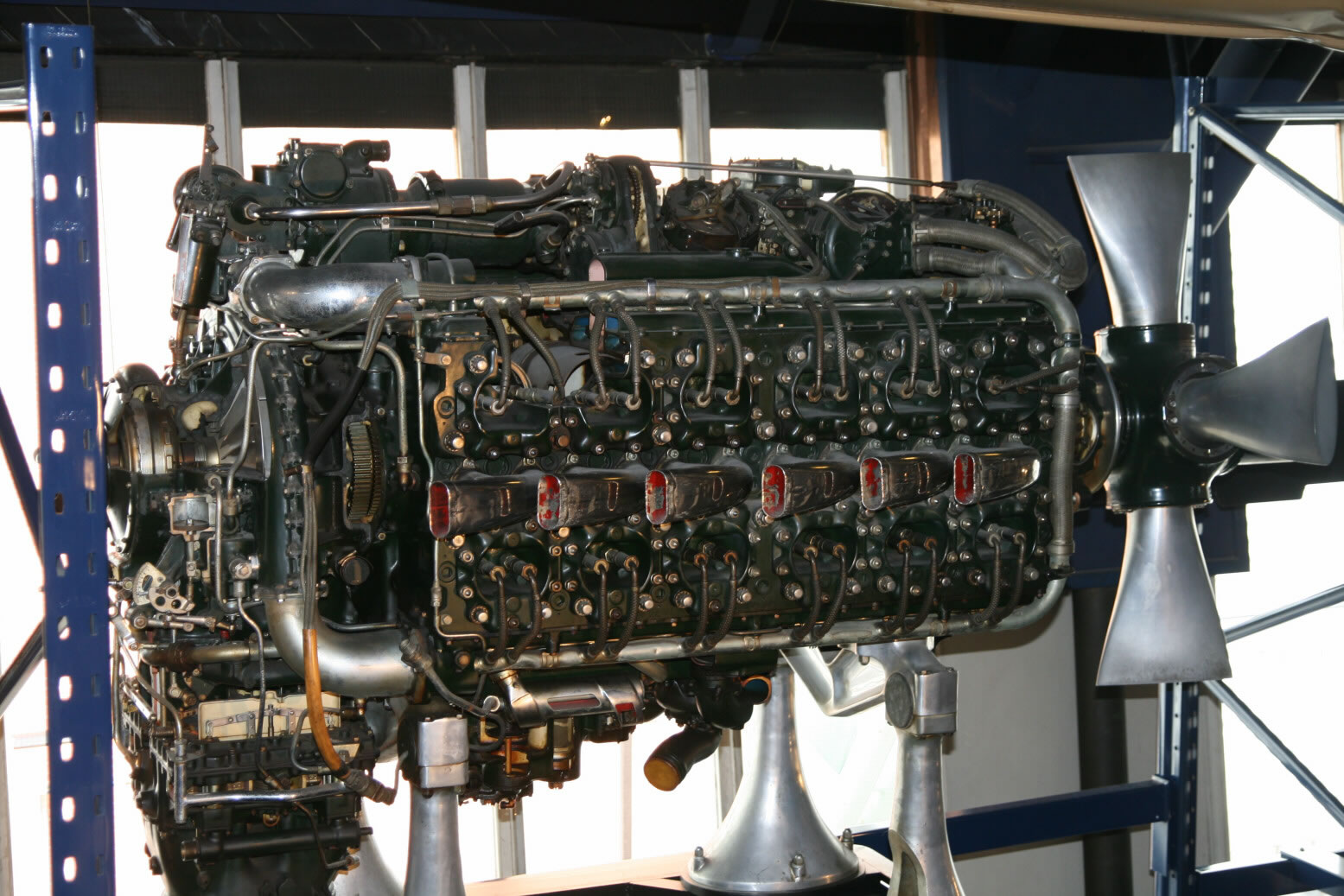
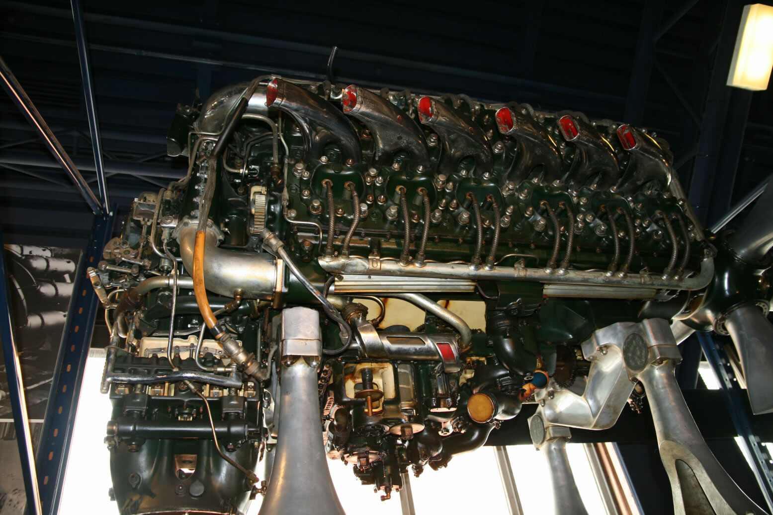
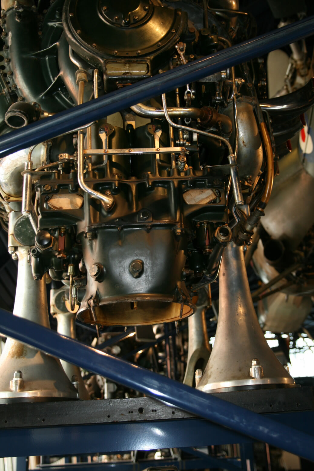
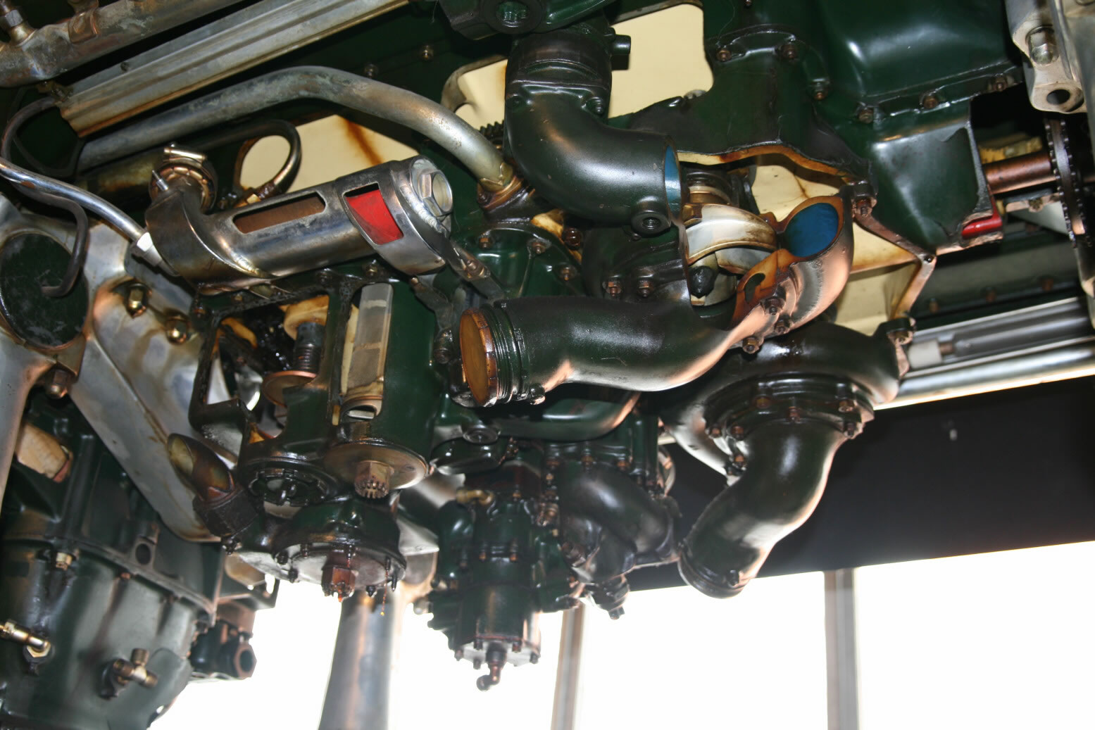
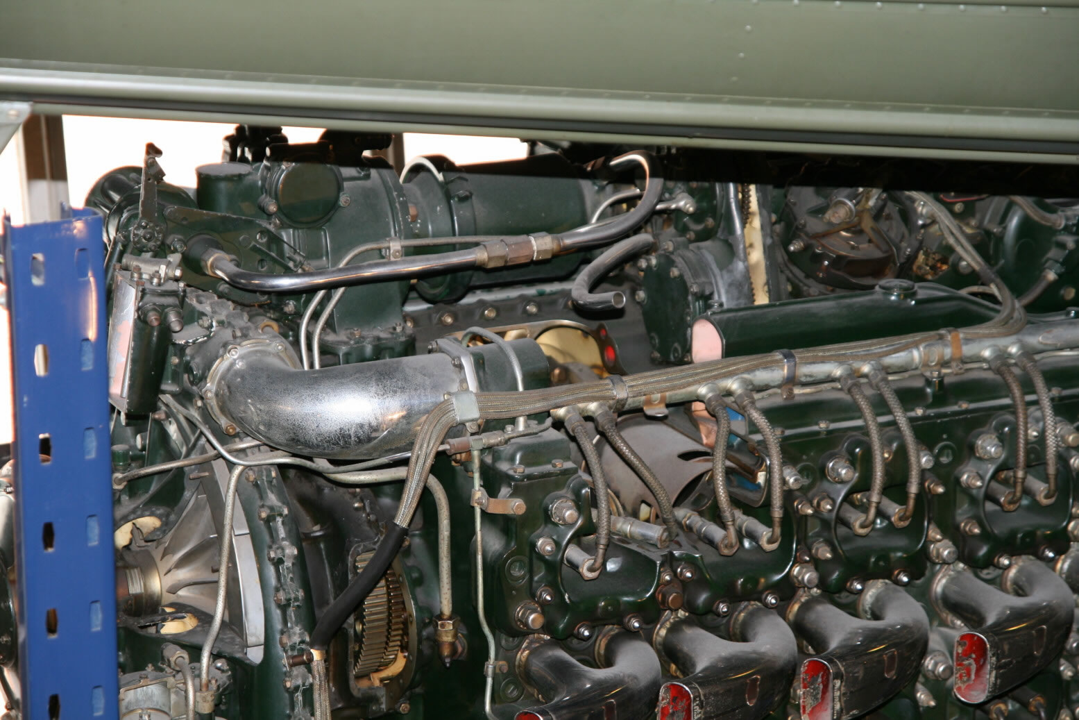
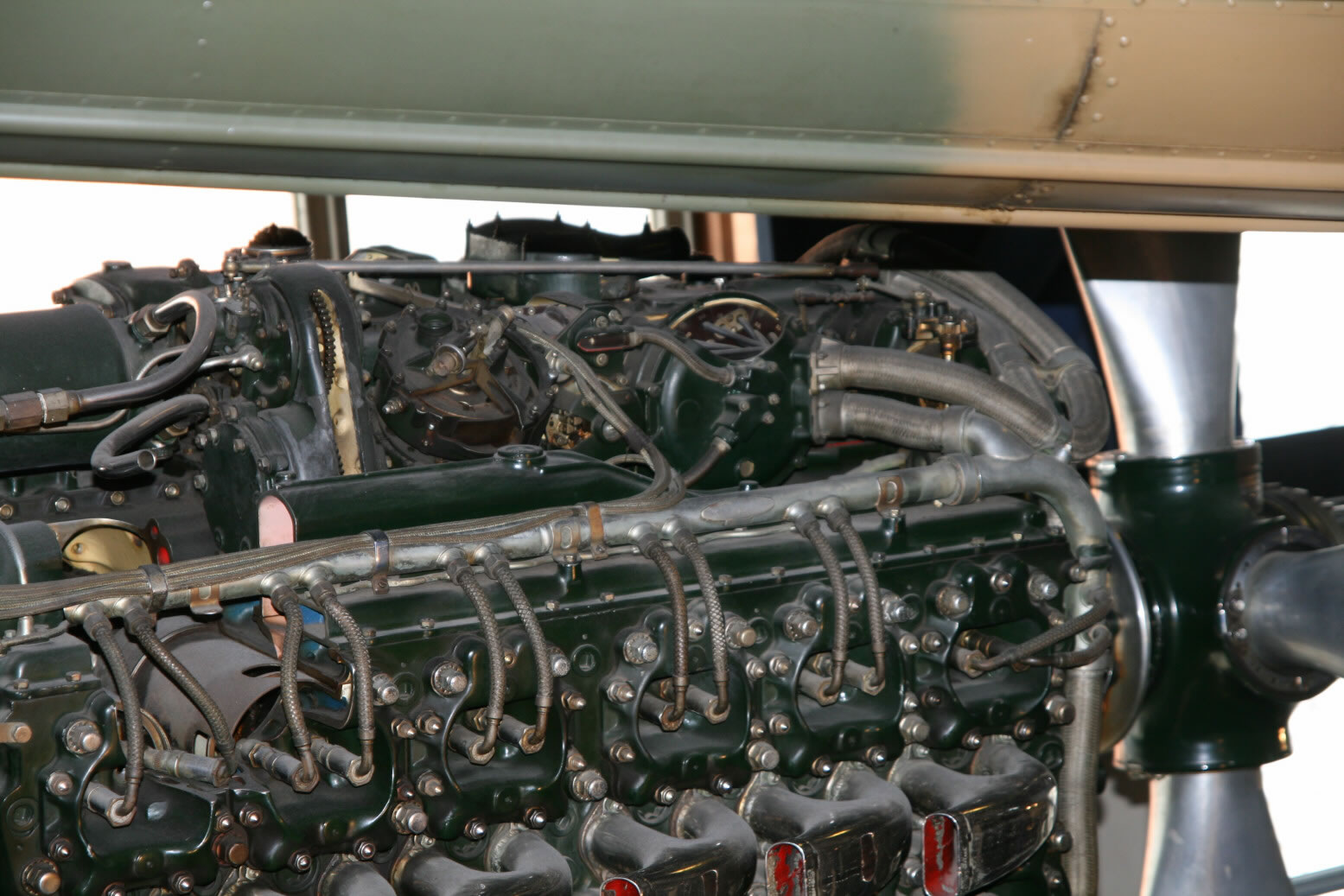
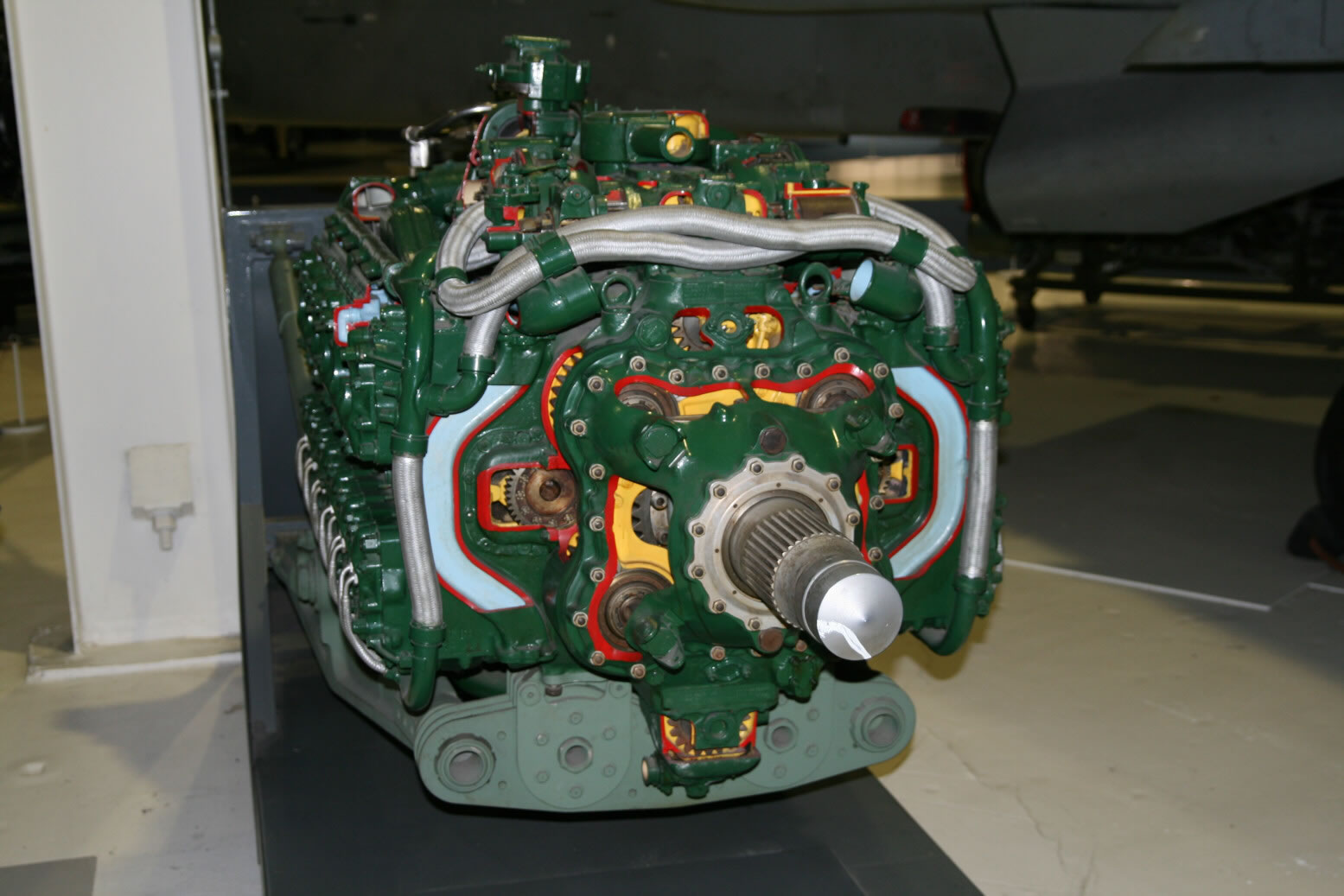
Photo 3 shows the side from slightly behind while photo 4 has the same angle but now from below. The unit visible in photo 3 on the top near the back is the Coffman cartridge starter, from back to front to the cartridge loader, with the lever standing vertically being the cartridge loading level, then the roughly cylindrical unit with the starting gears and finally the cylindrical Coffman starter. I think the round unit behind the distributor is a magneto. The fuel inlet pipes, exiting from the supercharger at top and bottom back, are also well visible.
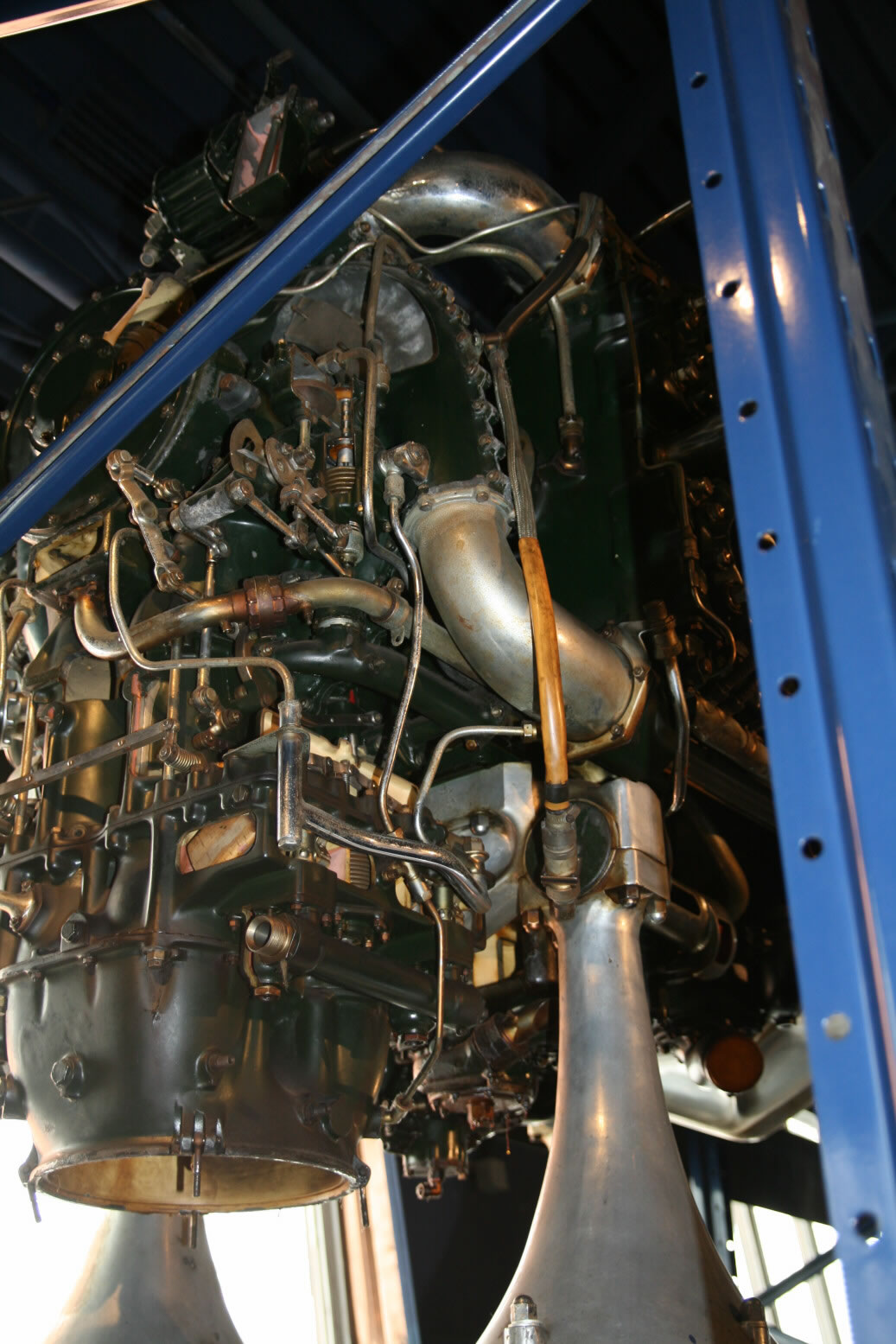
Photos 5 through 8 show a bunch of views of the back, moving on to the port side.
Photos 9 and 10 show the pumps underneath the engine. The coolant pump is one most up front, the oil pump is on the starboard side and the fuel pump on the port side.
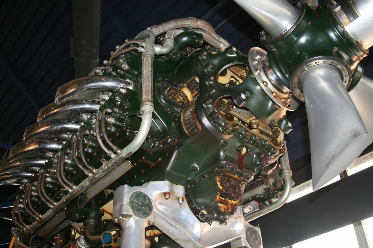
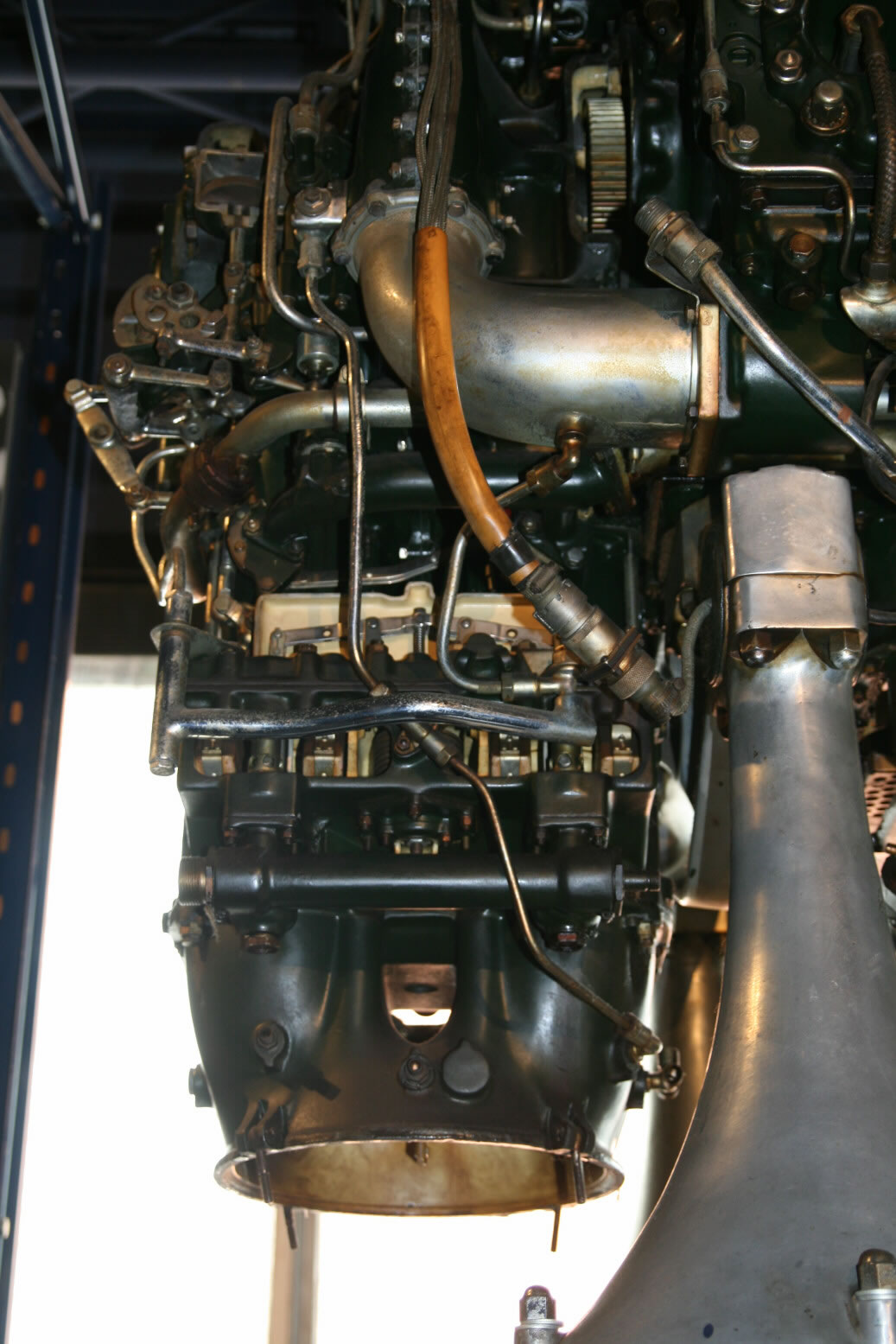
Photo 11 shows a view of the front bottom of the engine.
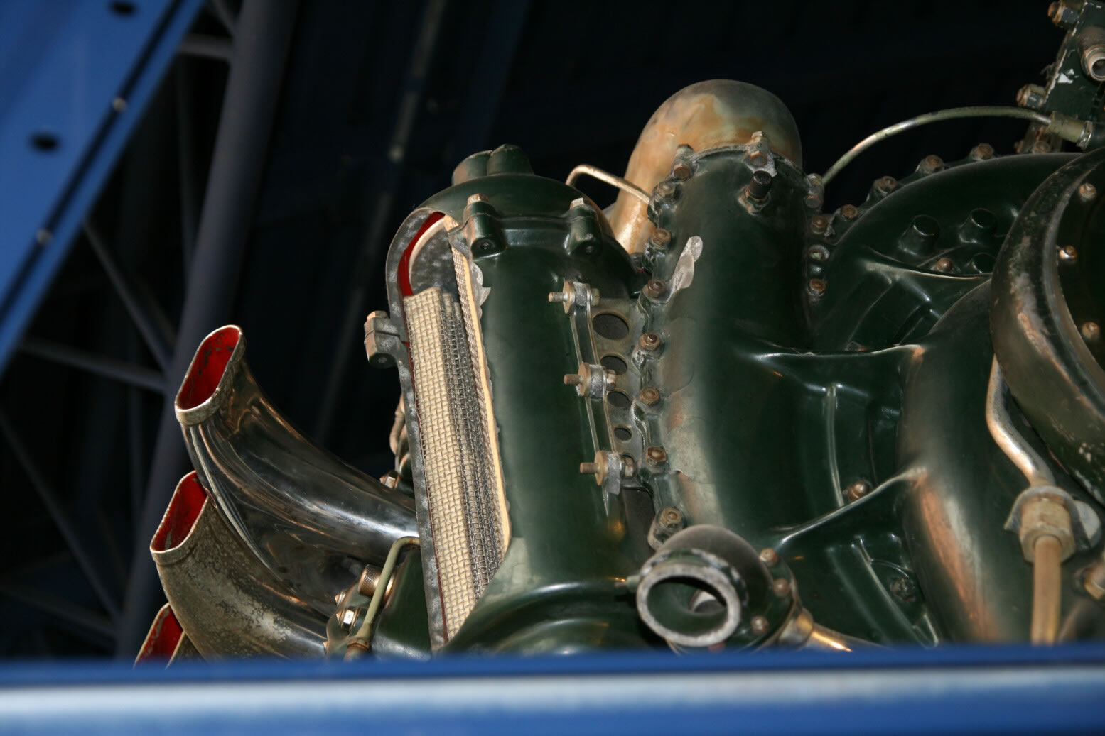
Photo 12 shows a view from a below of the port backside of the engine. There is a (cut open) unit there mounted against the supercharger which looks like some kind of filter (air filter?).
Photos 13 through 15 show the top of the engine, obscured by the bottom of the aircraft that hangs in front.
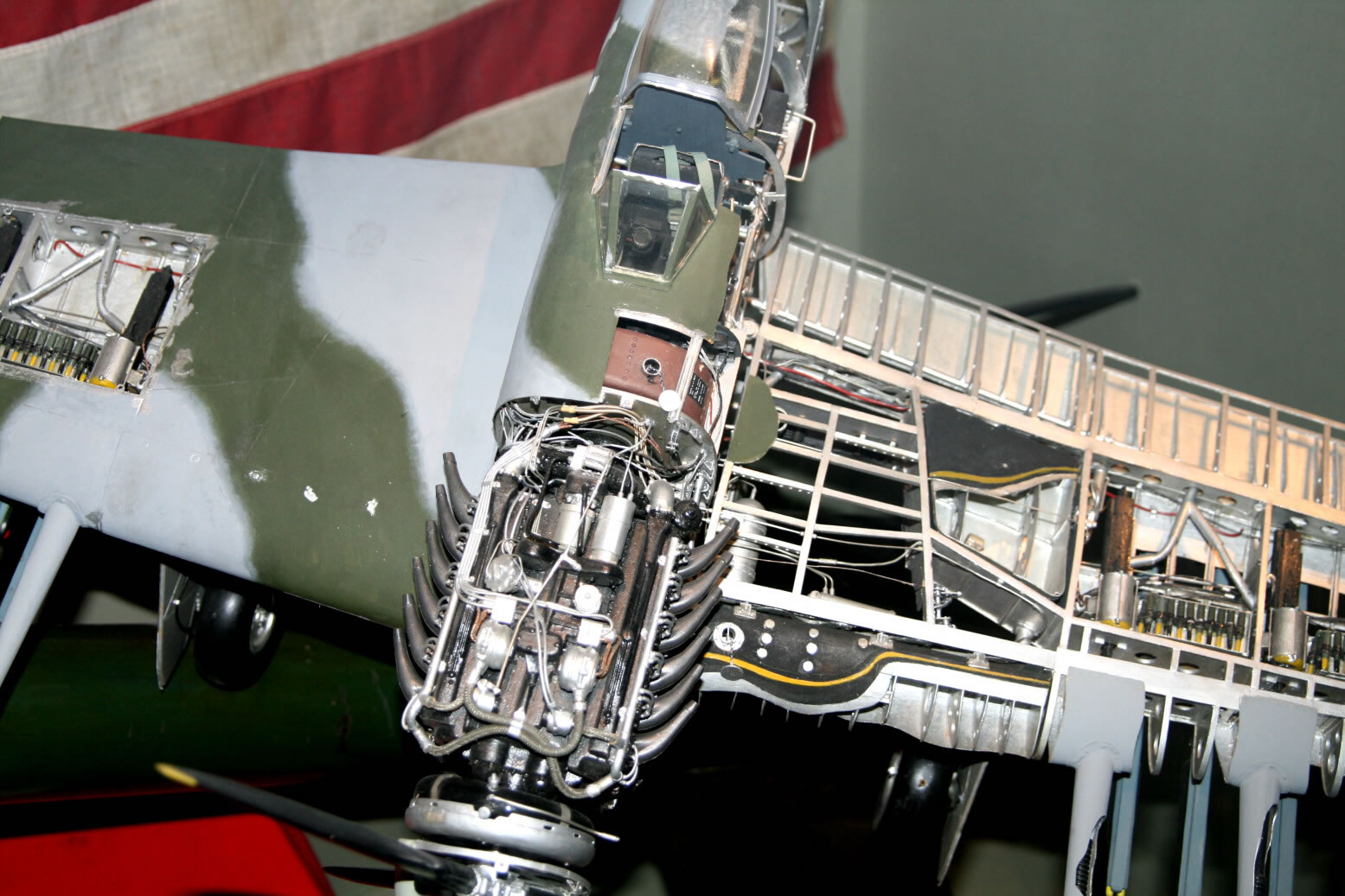
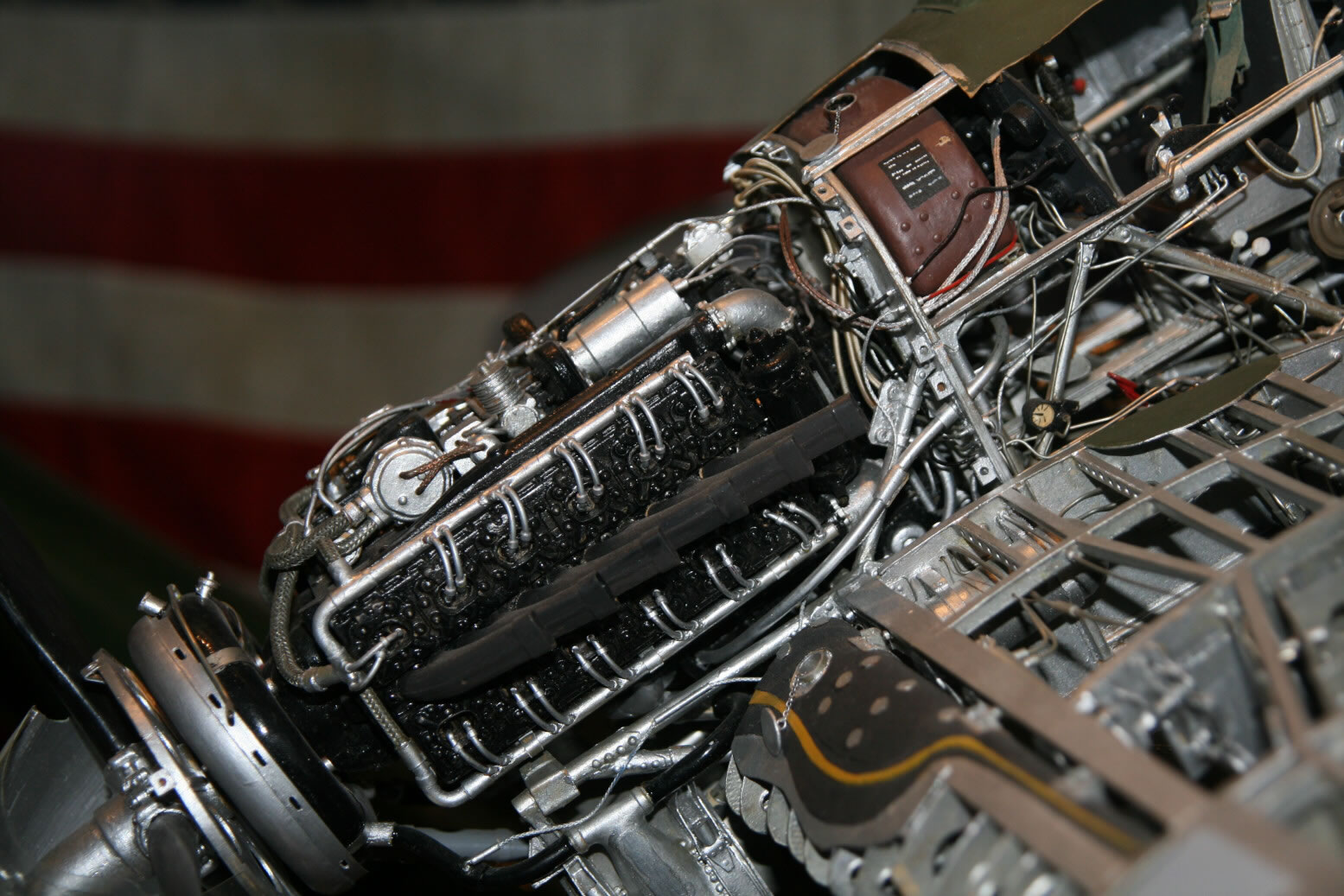
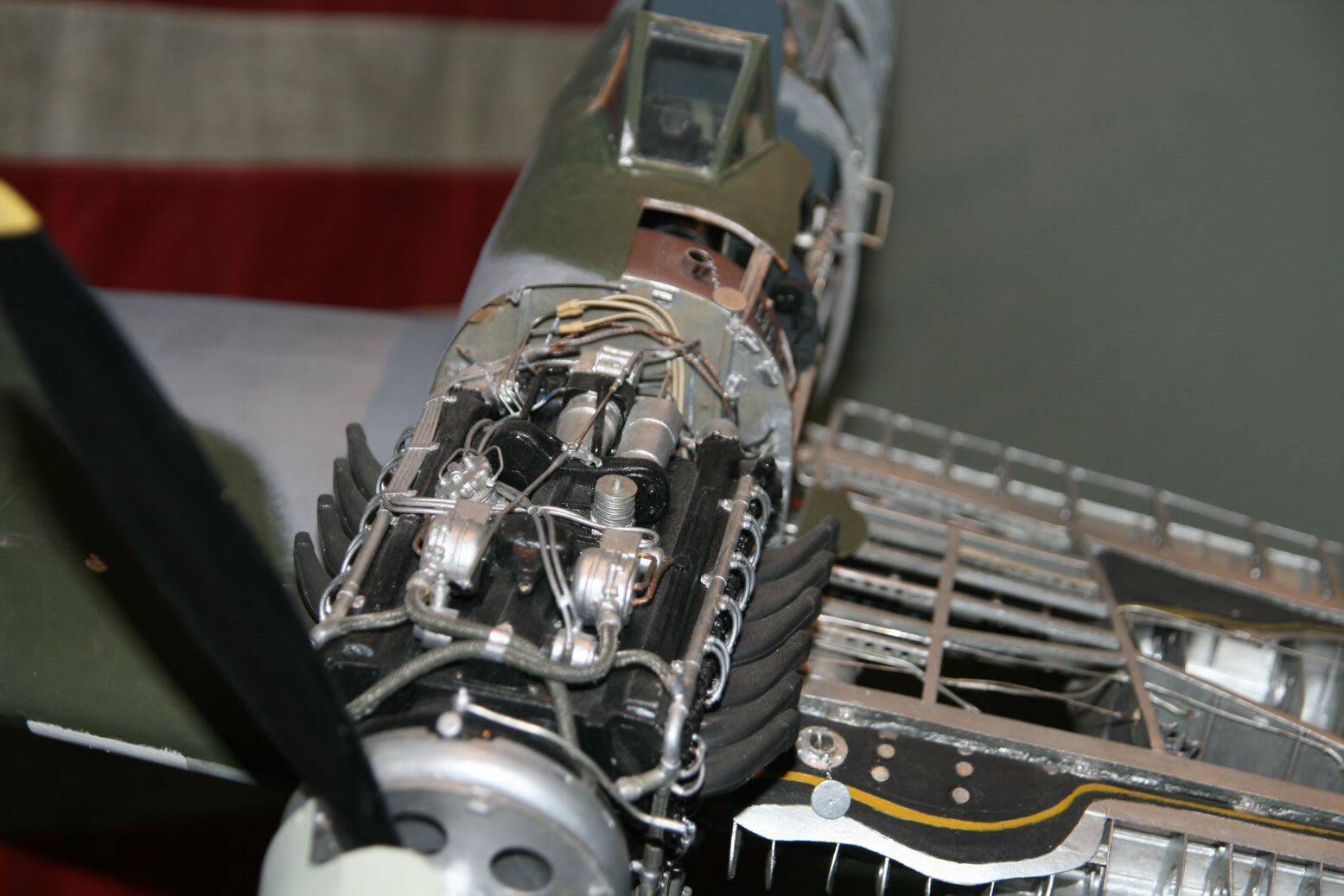
With regard to the problem with the view of the top of the engine, I did come across a gem of a model of the Hawker Typhoon at the Imperial War Museum (London). It's big (I am guessing 1:16), cut away and highly detailed. And it shows the engine layout on top quite well. In photos 16 through 18 you see from front to back the ignition wiring crossing over the front, going from the distributors on either side to the spark plugs. Just in front of the distributors are vacuum pumps. The square units as seen from the top are the magnetos. The cylindrical unit that follows on the port side is the compressor (in reference drawings it looks like a stack of cooling plates with at the top cooling plates also in the vertical direction). On the starboard side is the hydraulics pump. Behind the compressor follows the generator on the port side, while the Coffman starter is in the center.
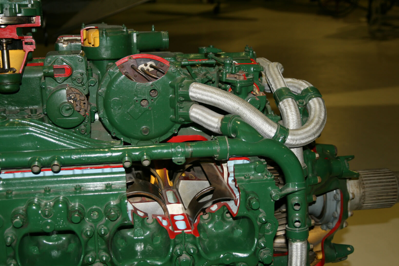
A further set of three photos (19 through 21) comes from the RAF Museum at Hendon (London). Also this engine has been cut open in various places (the red-rimmed areas). Note that both the Science Museum and RAF Museum Sabres are painted green, though the color in the Science Museum is somewhat more subdued.
© Max Otten 2013
This article created on Friday, February 14 2014; Last modified on Thursday, March 31 2016