
Rolls-Royce Merlin 61
Photos By Max Otten
Photos were taken at the South African Military History Museum, Johannesburg (South Africa) in 2015.
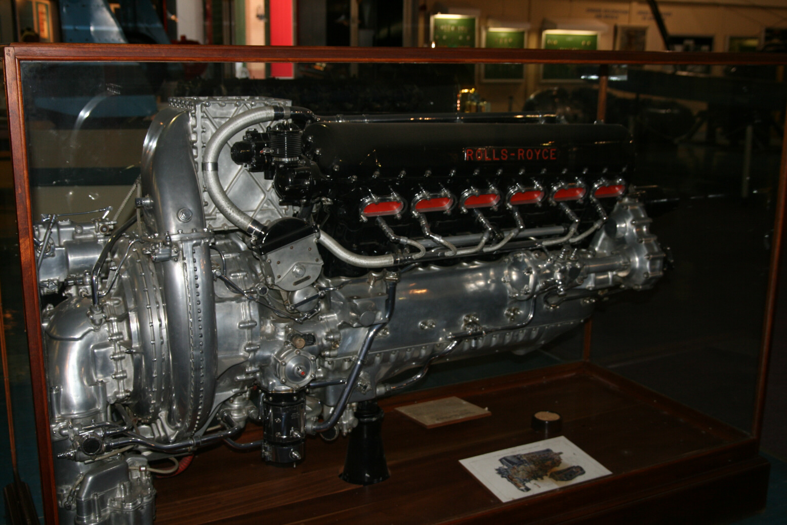
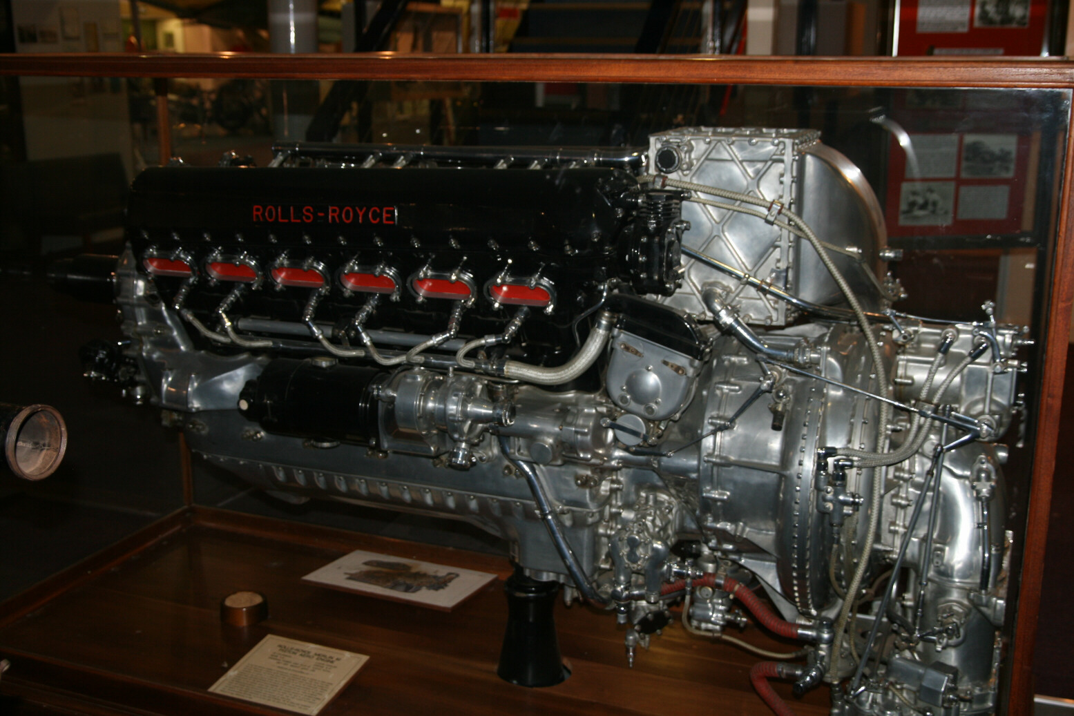
The museum has two Merlin engines that have been stripped of paint and polished. Although obviously not in their original colour, it makes detail much more easily visible than on their standard black-painted counterparts. The engines are displayed in glass cabinets which occasionally makes flash photography a bit difficult so if you see odd features in the photos, remember that they just might be reflections.
One of the engines is a Merlin 61, which is a two-stage supercharged version as was used for example in the museum’s Spitfire VIII.
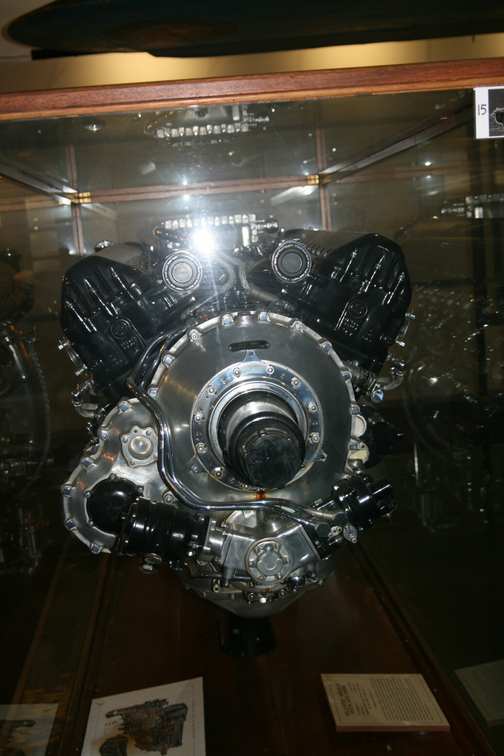
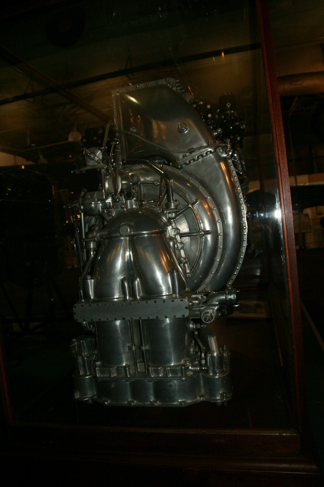
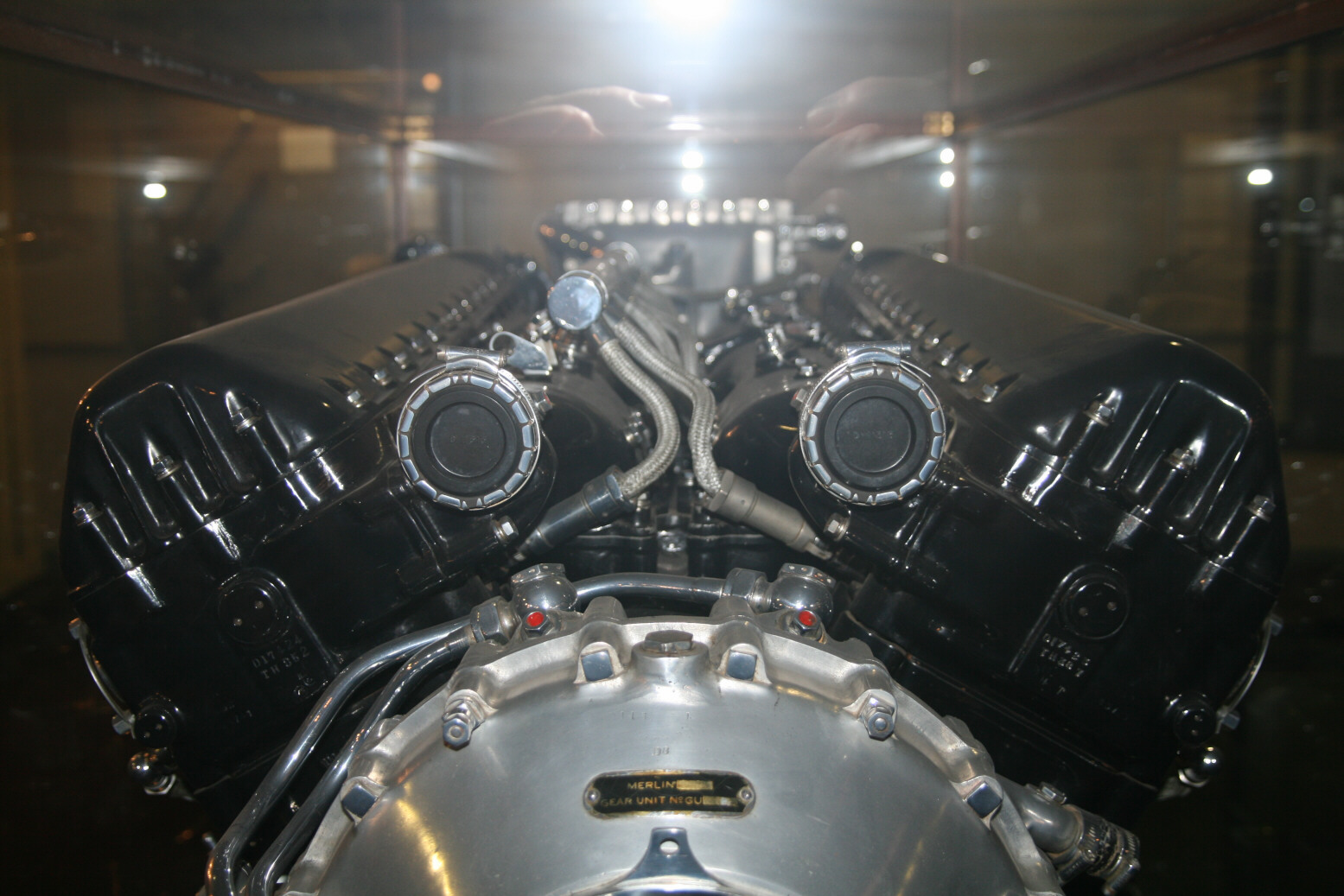
Photos 1 through 4 (below) start off with an overview, starboard, port, front and back. Photo 4 is at an odd angle, that’s my fault.
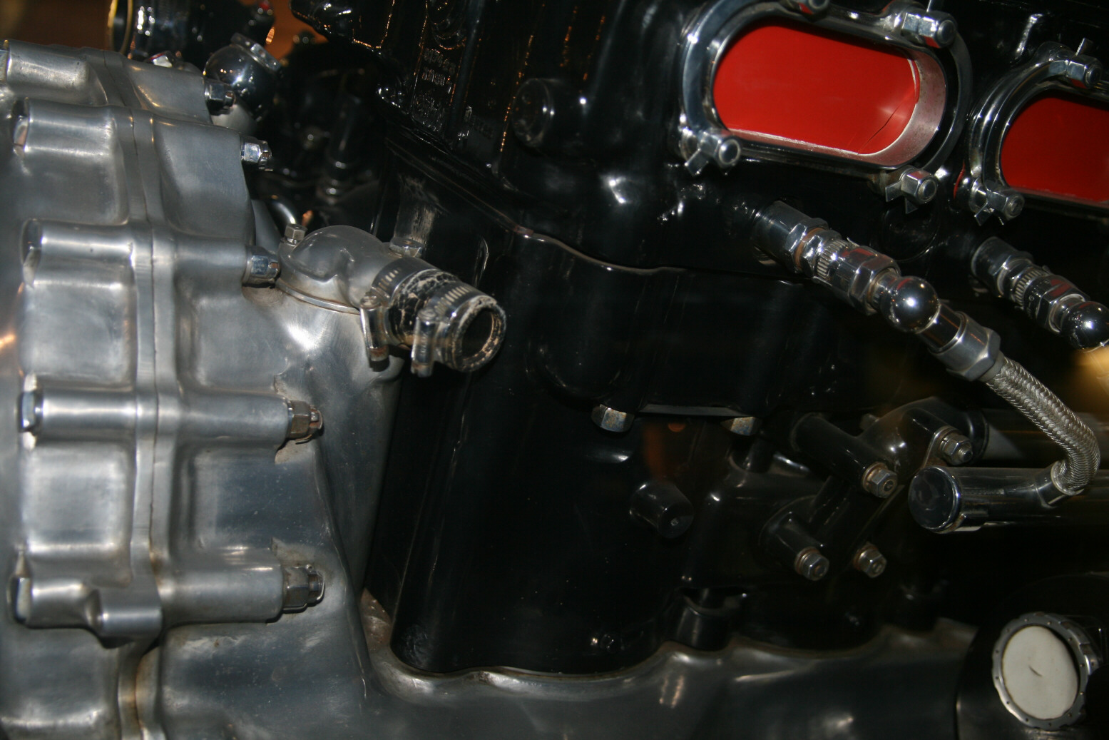
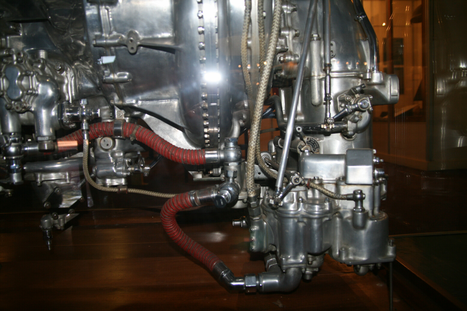
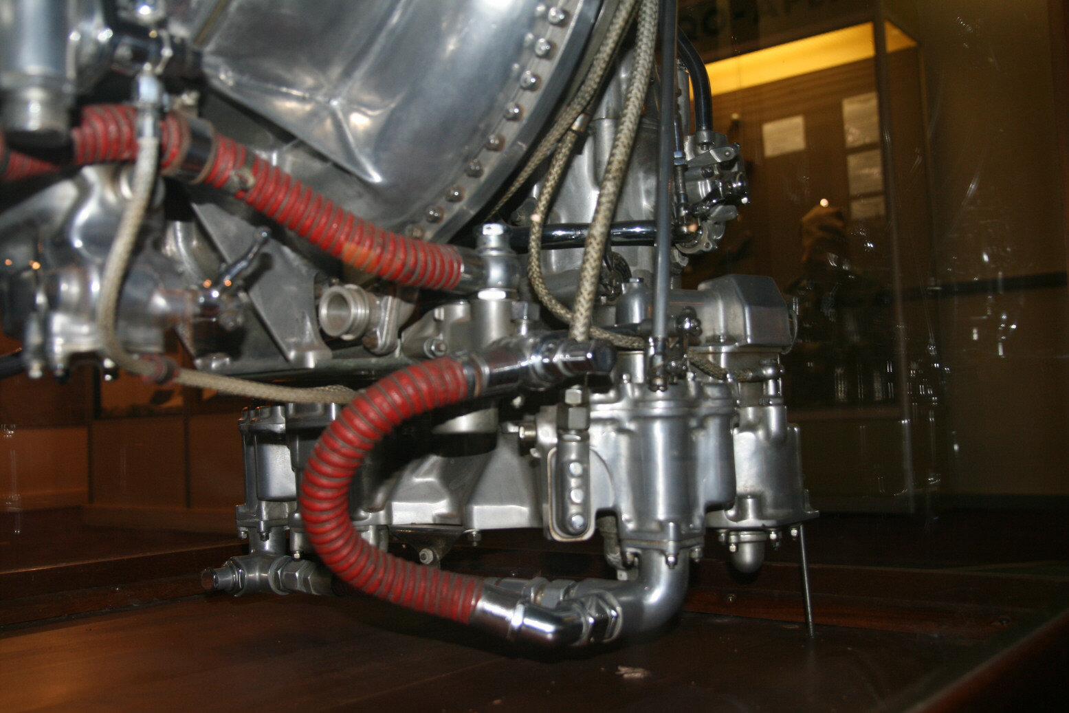
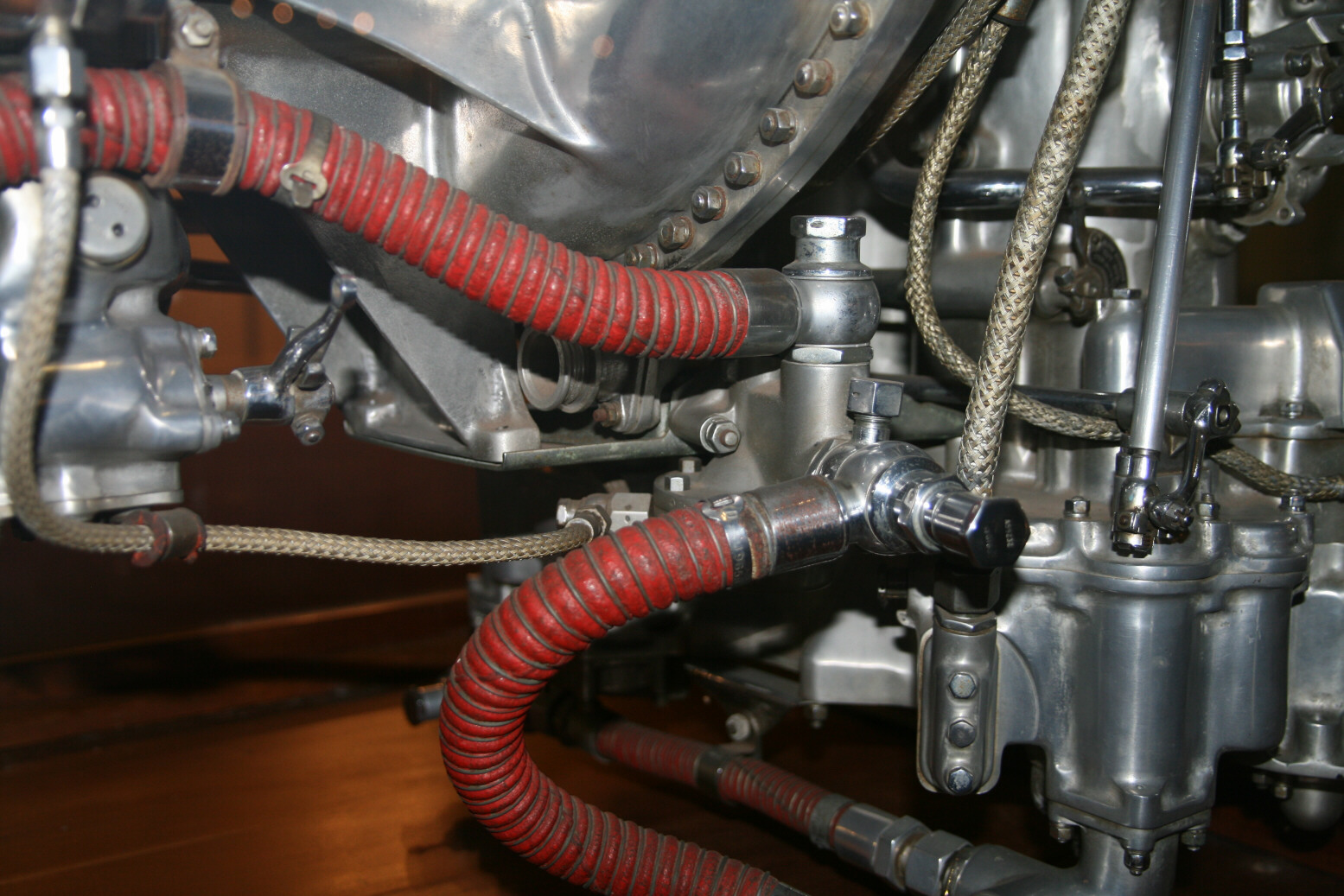
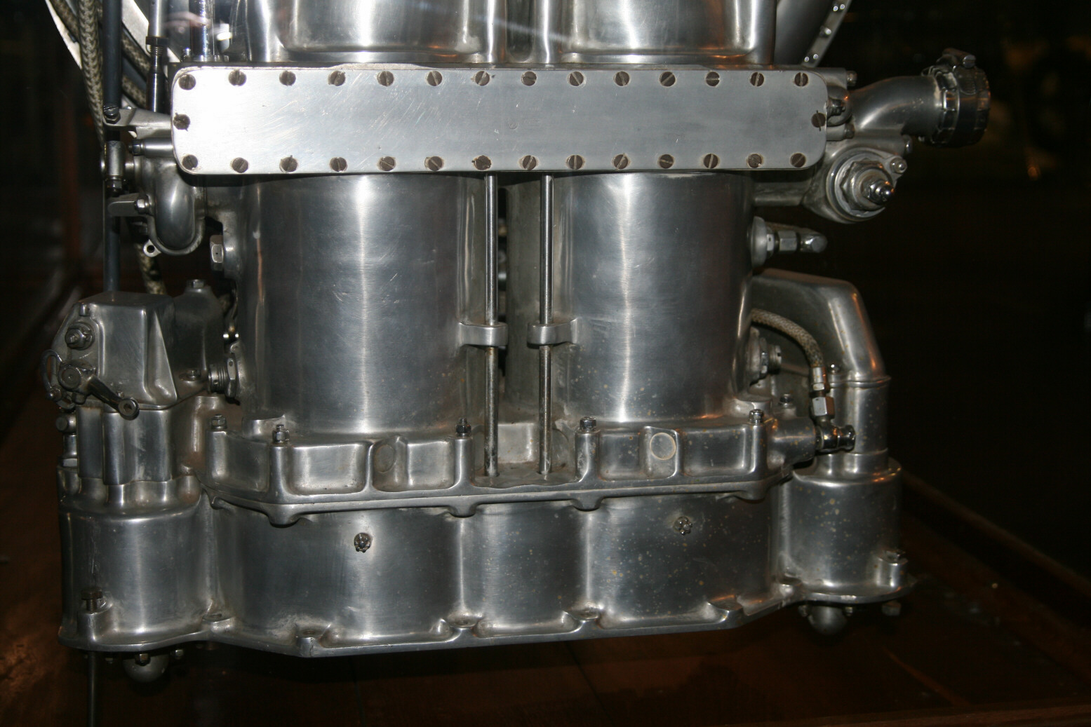
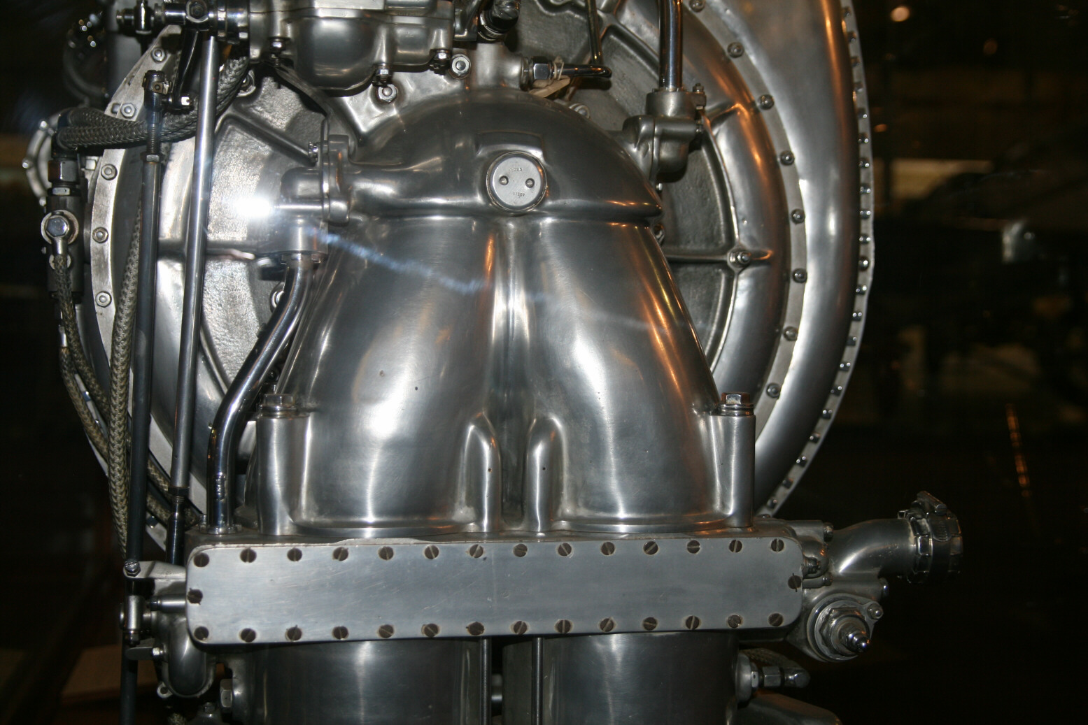
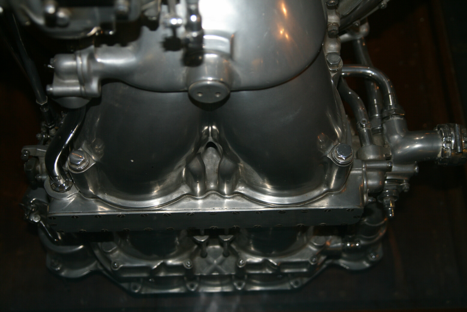
We will first walk around the engine, going from the back around to starboard. Photos 5 through 7 (below) show the bottom of the air intake with the carburetors, one on this side, the other one on the port side. The red pipes are fuel lines, coming from the fuel pump. The pipes above the carburetor are for cooling fluid to the intake of the supercharger (I’m not sure if this is meant for cooling or warming the air coming in).
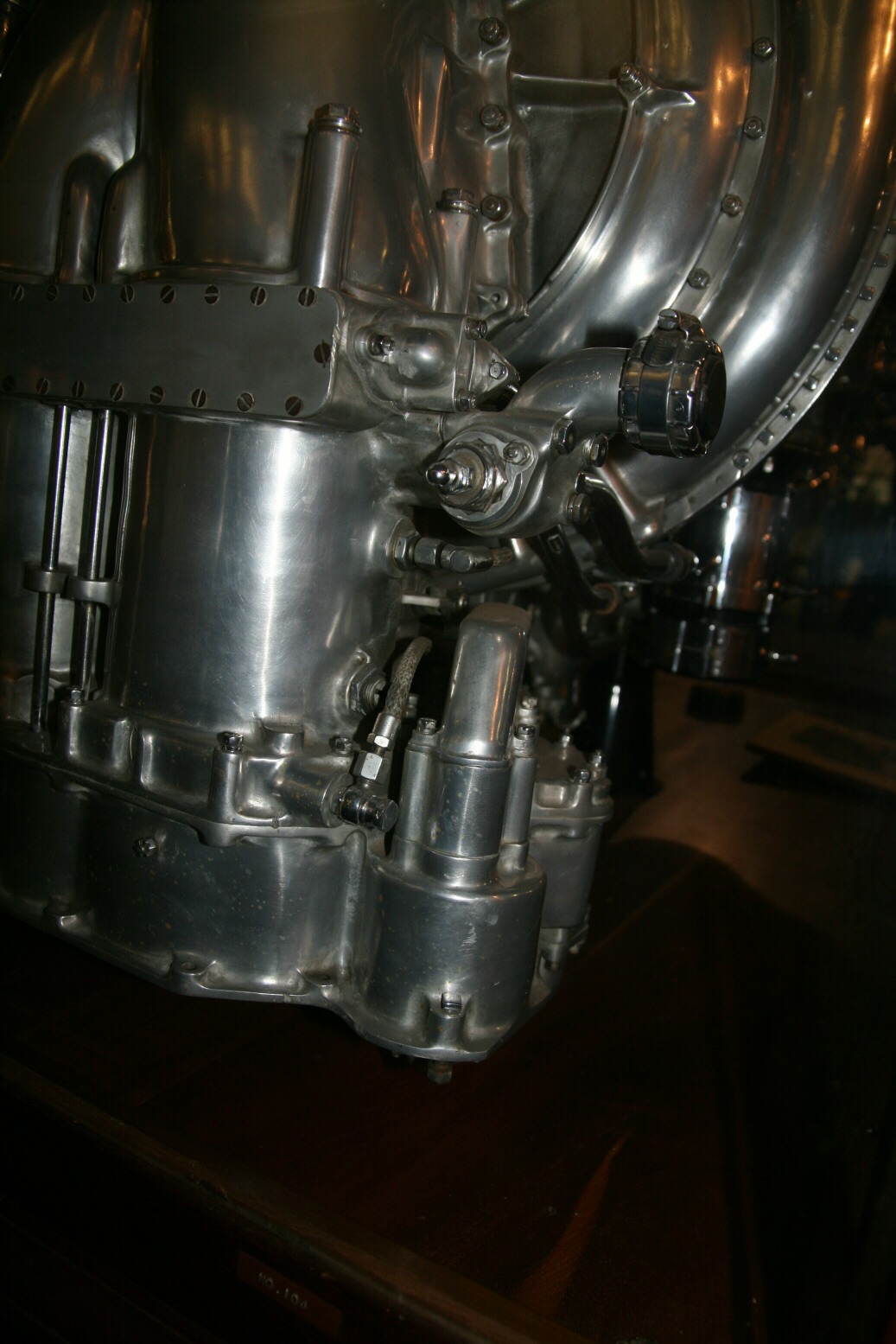
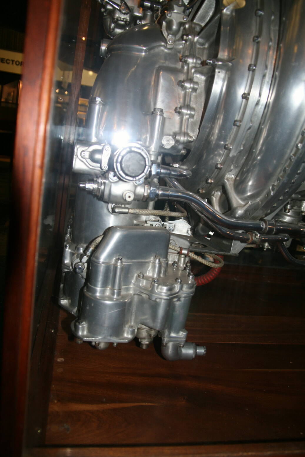
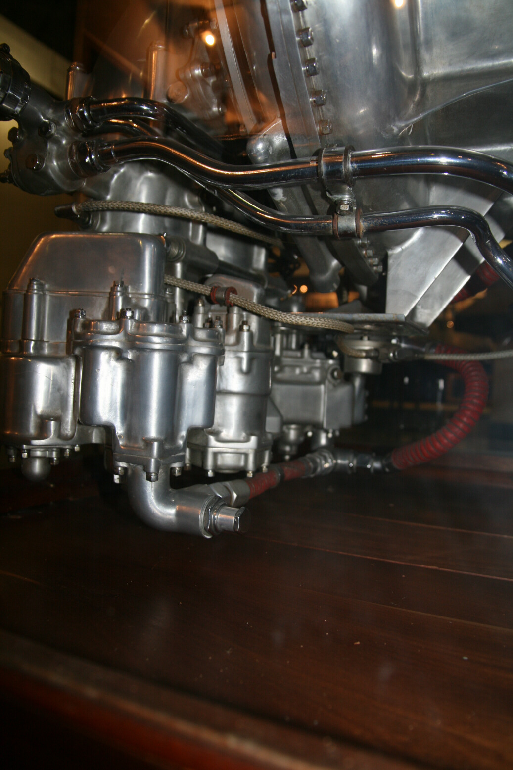
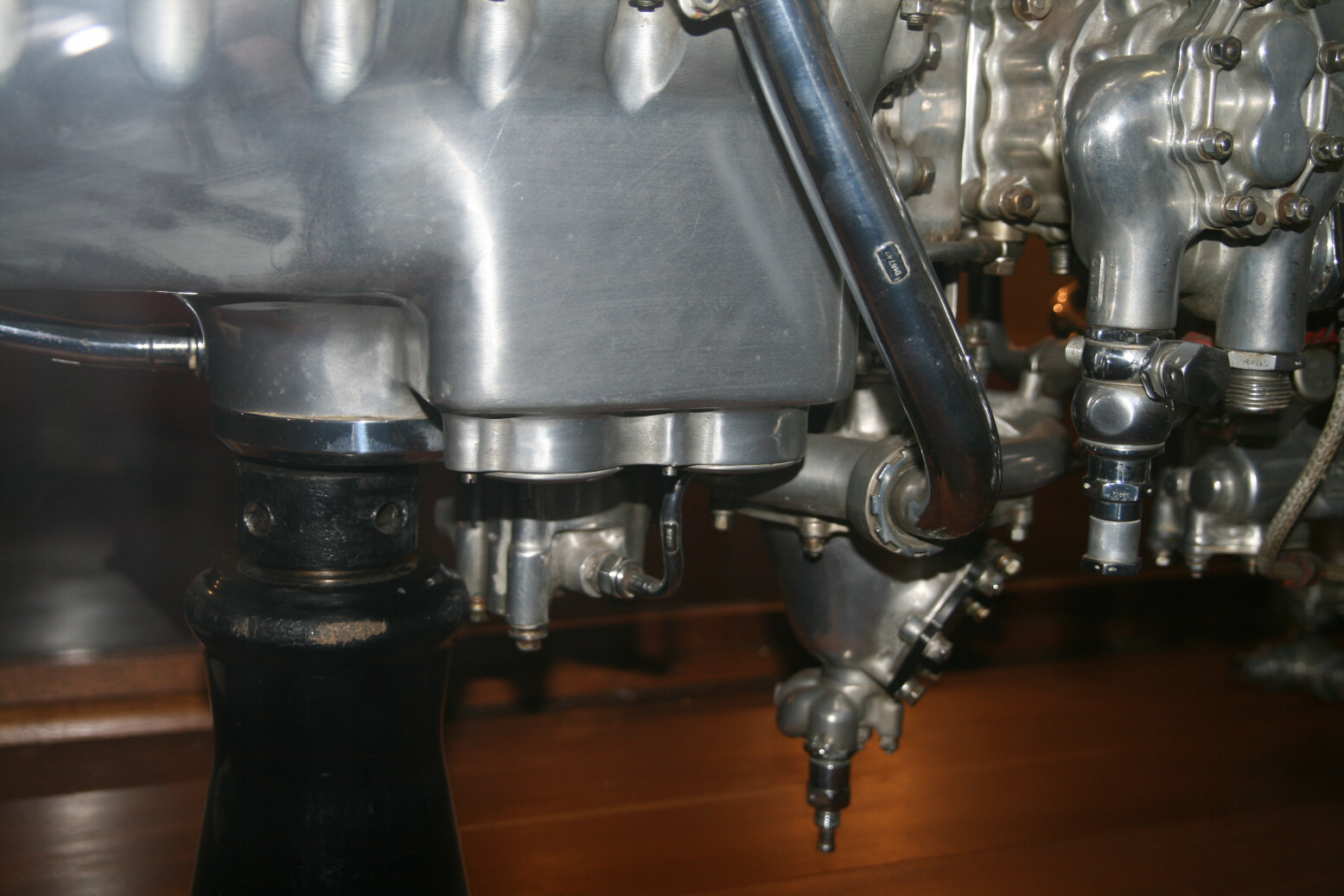
Photo 8 (below) shows the electrical starter motor. The two connectors sticking out at the bottom, one above the other, would be connected with cables to the access panel underneath the nose of the aircraft (if a Spitfire) for the starter trolley.
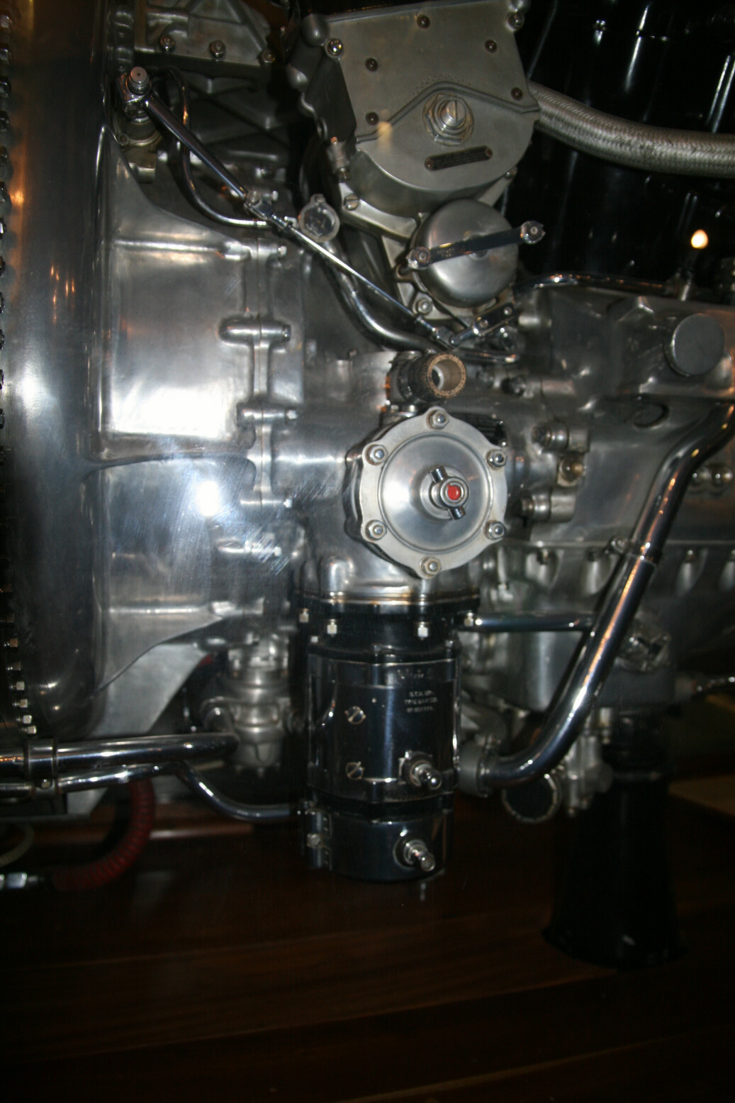
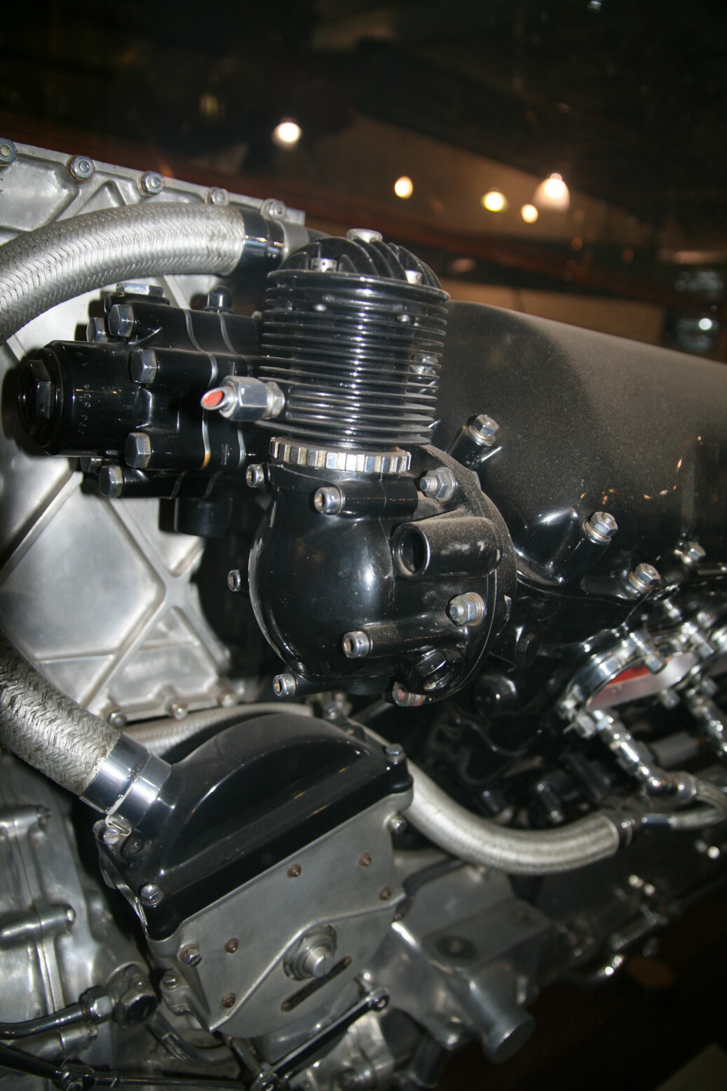
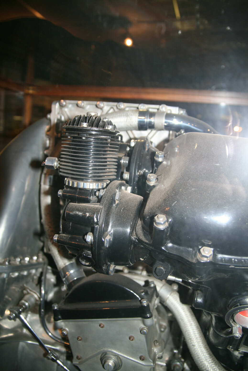
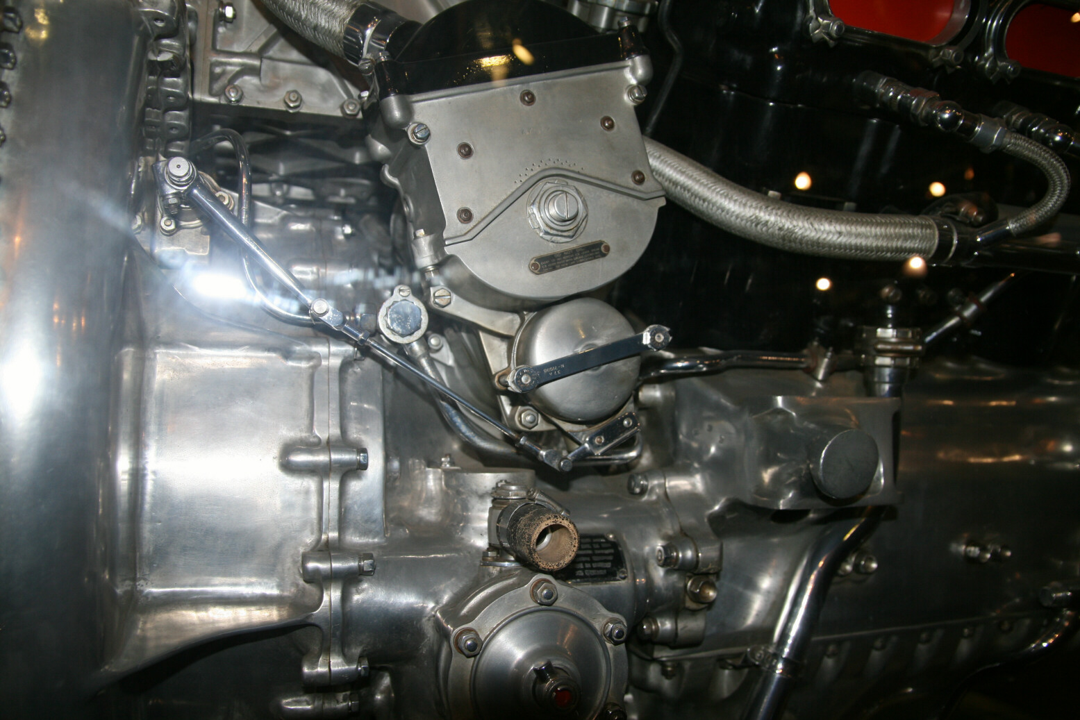
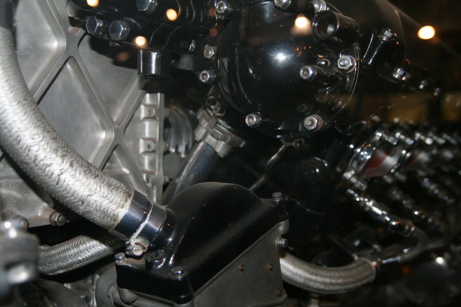
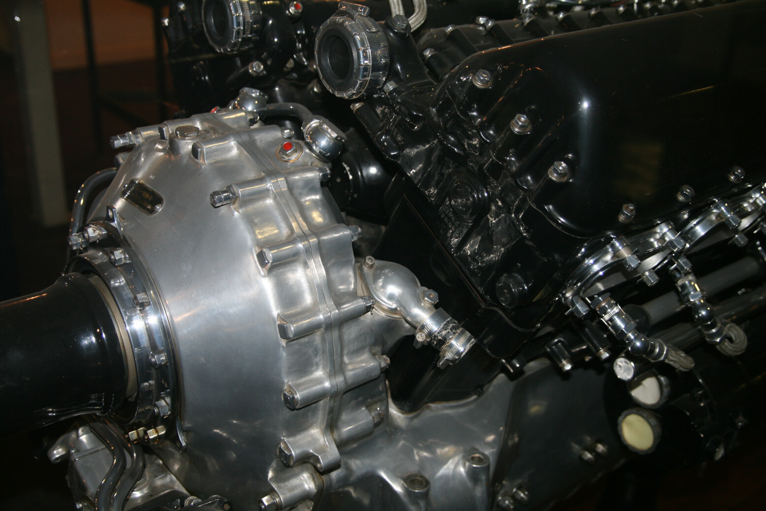
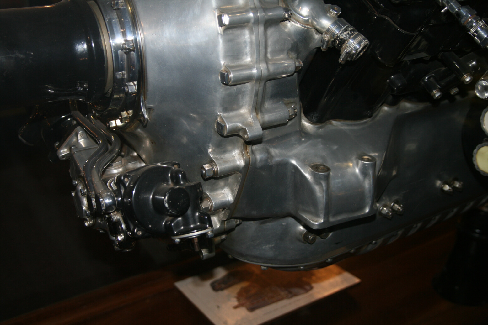
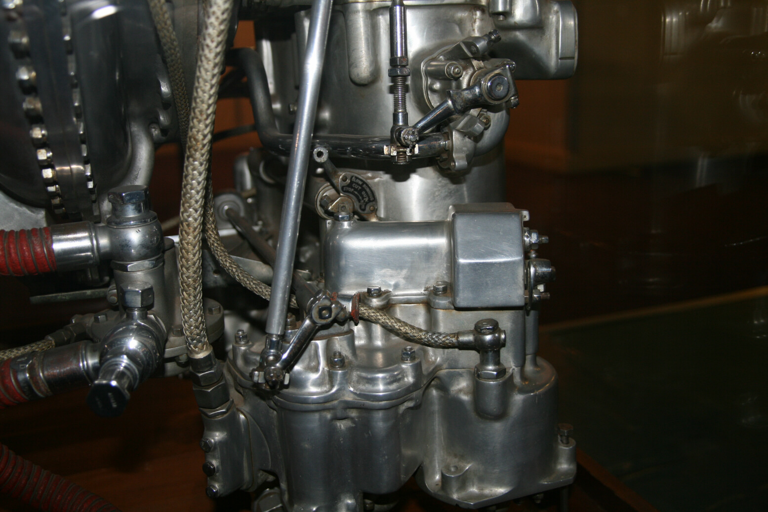
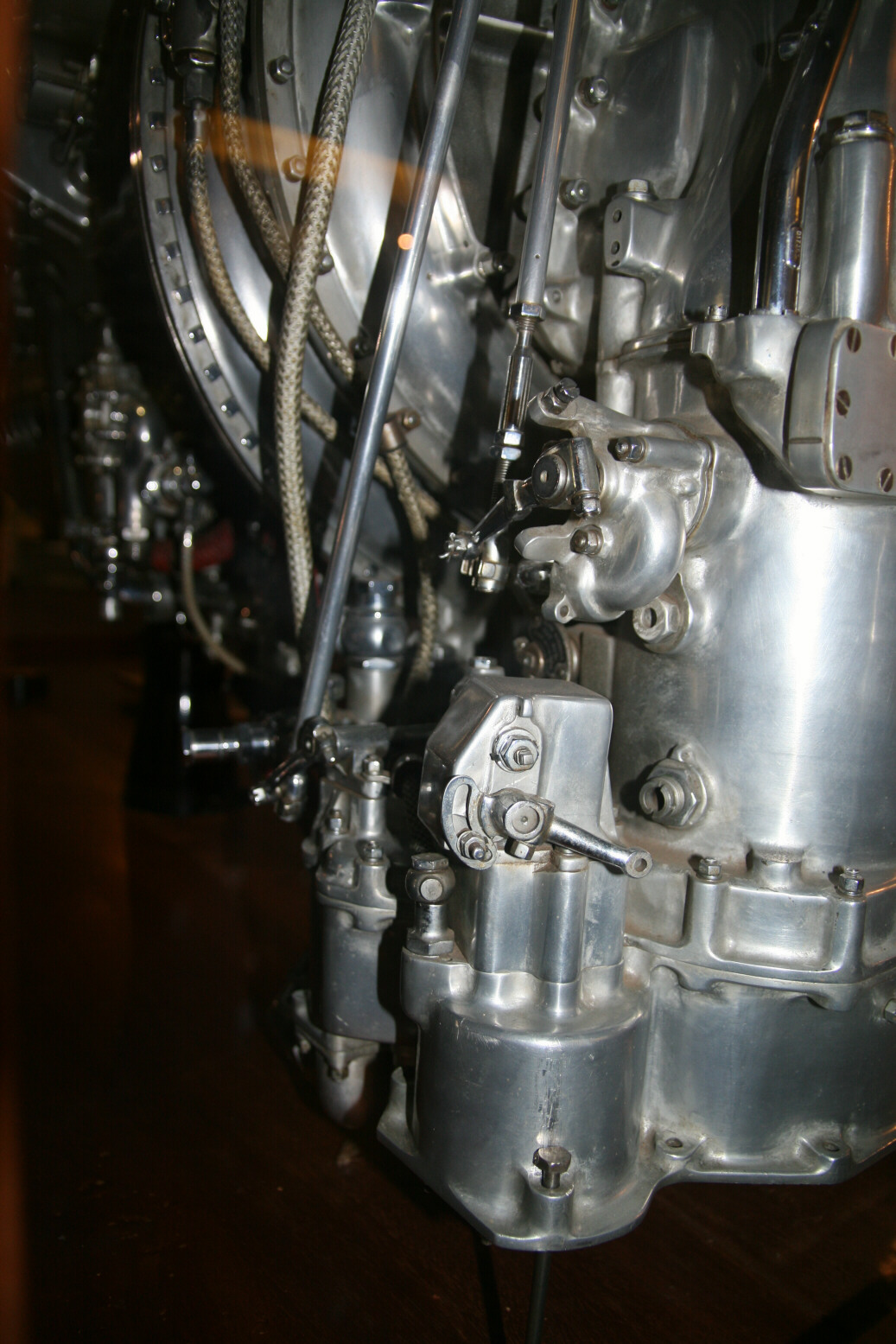
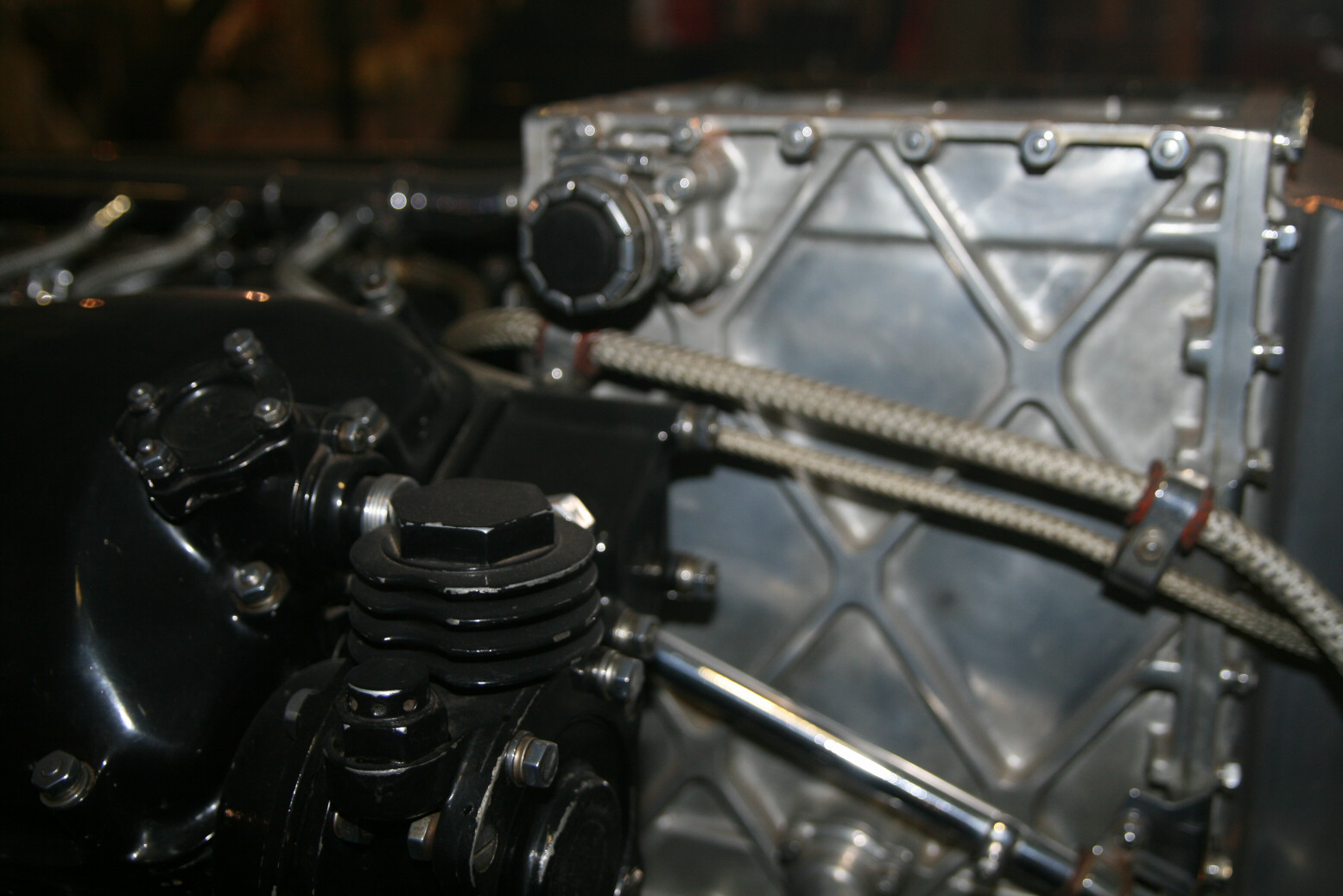
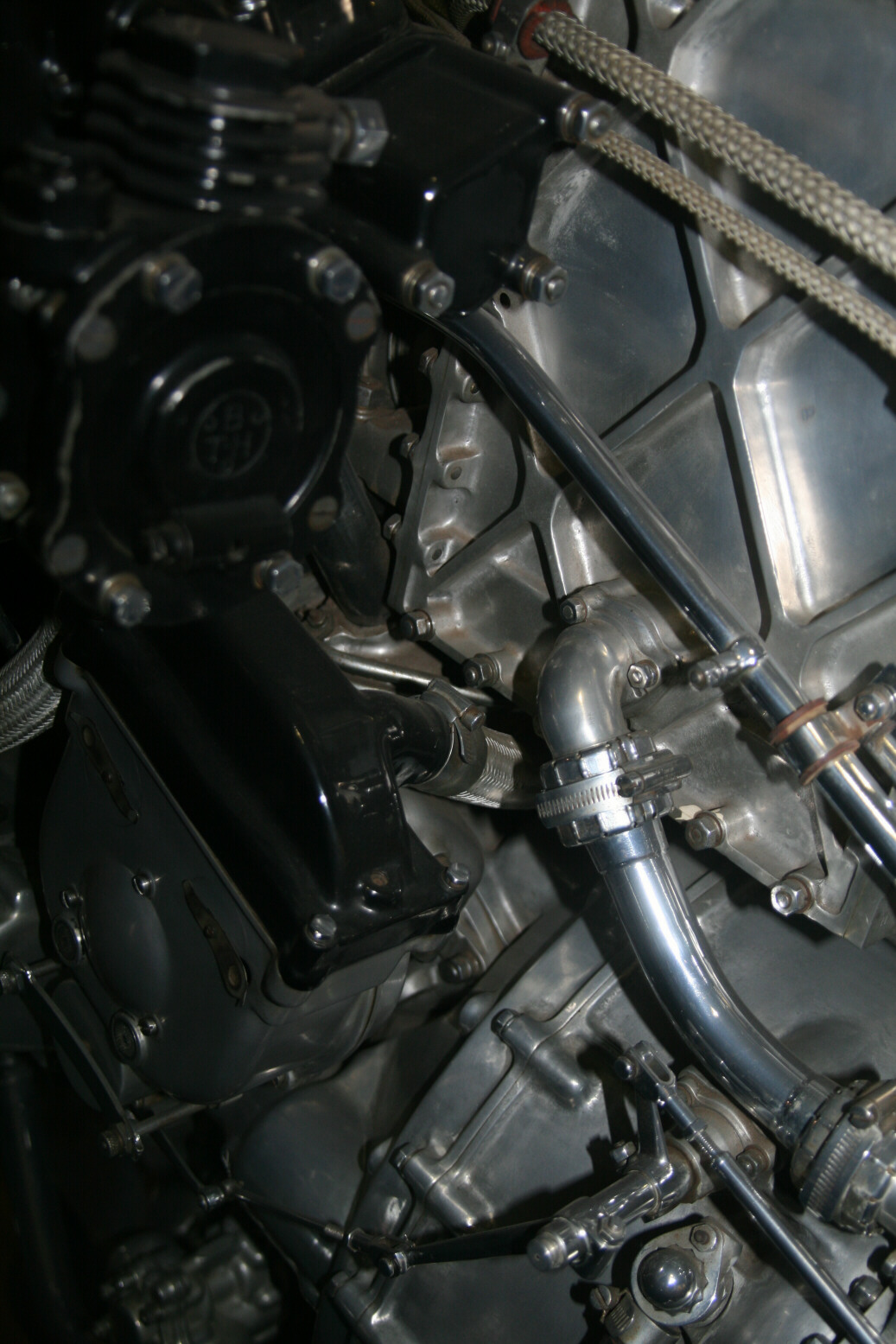
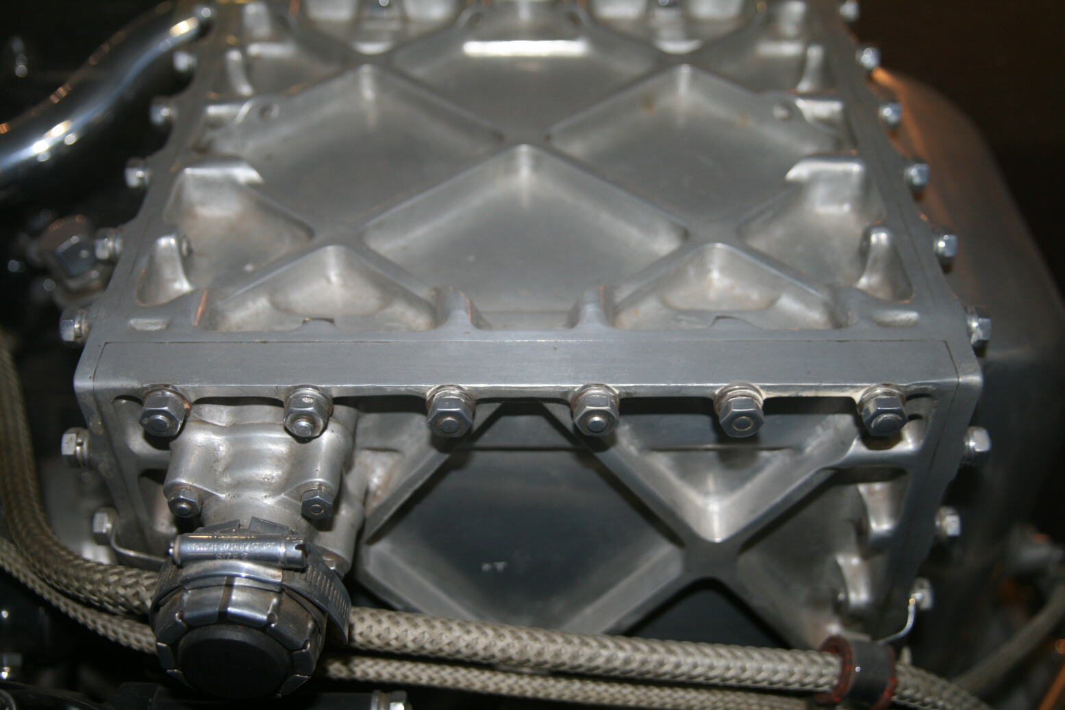
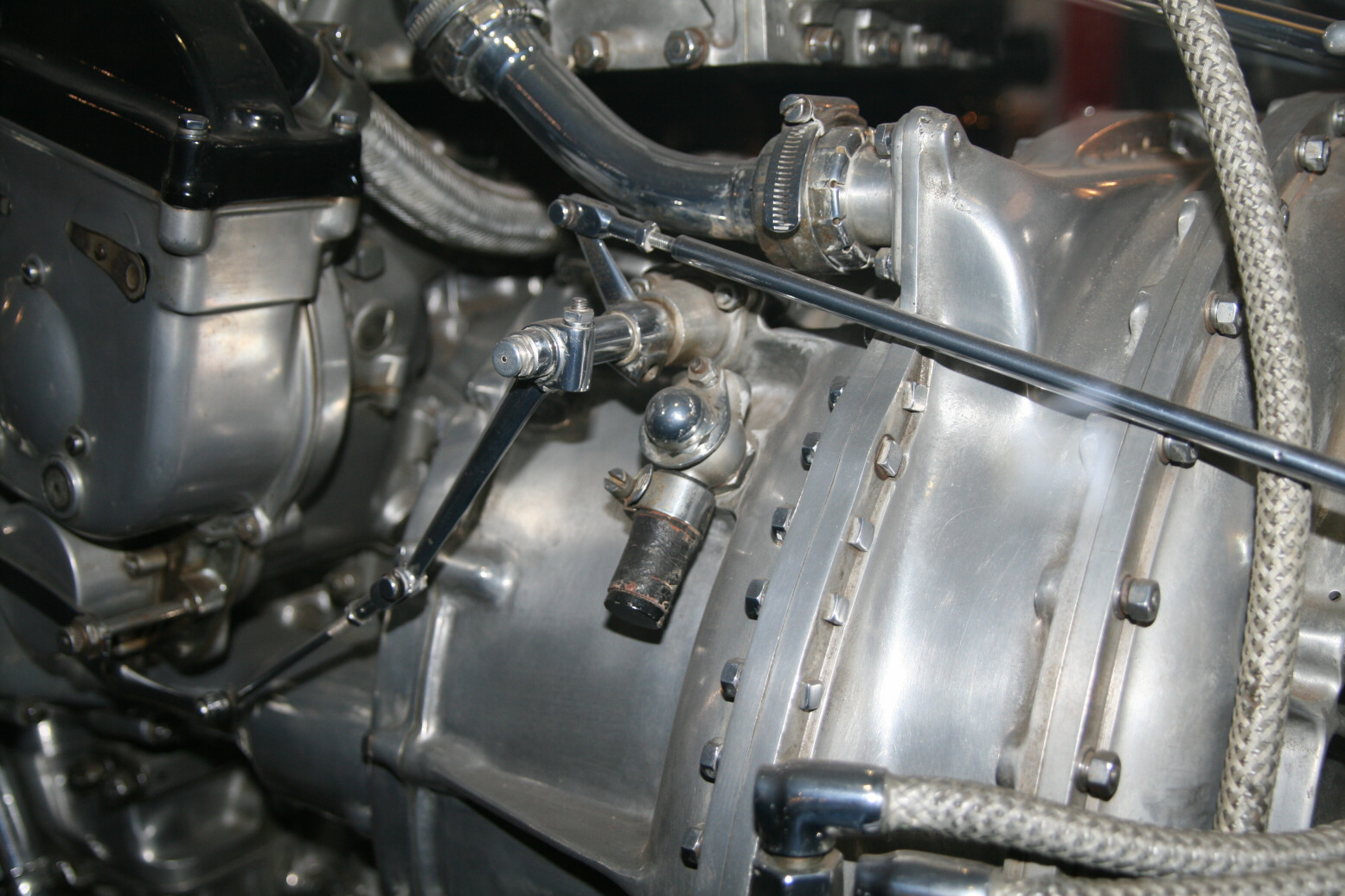
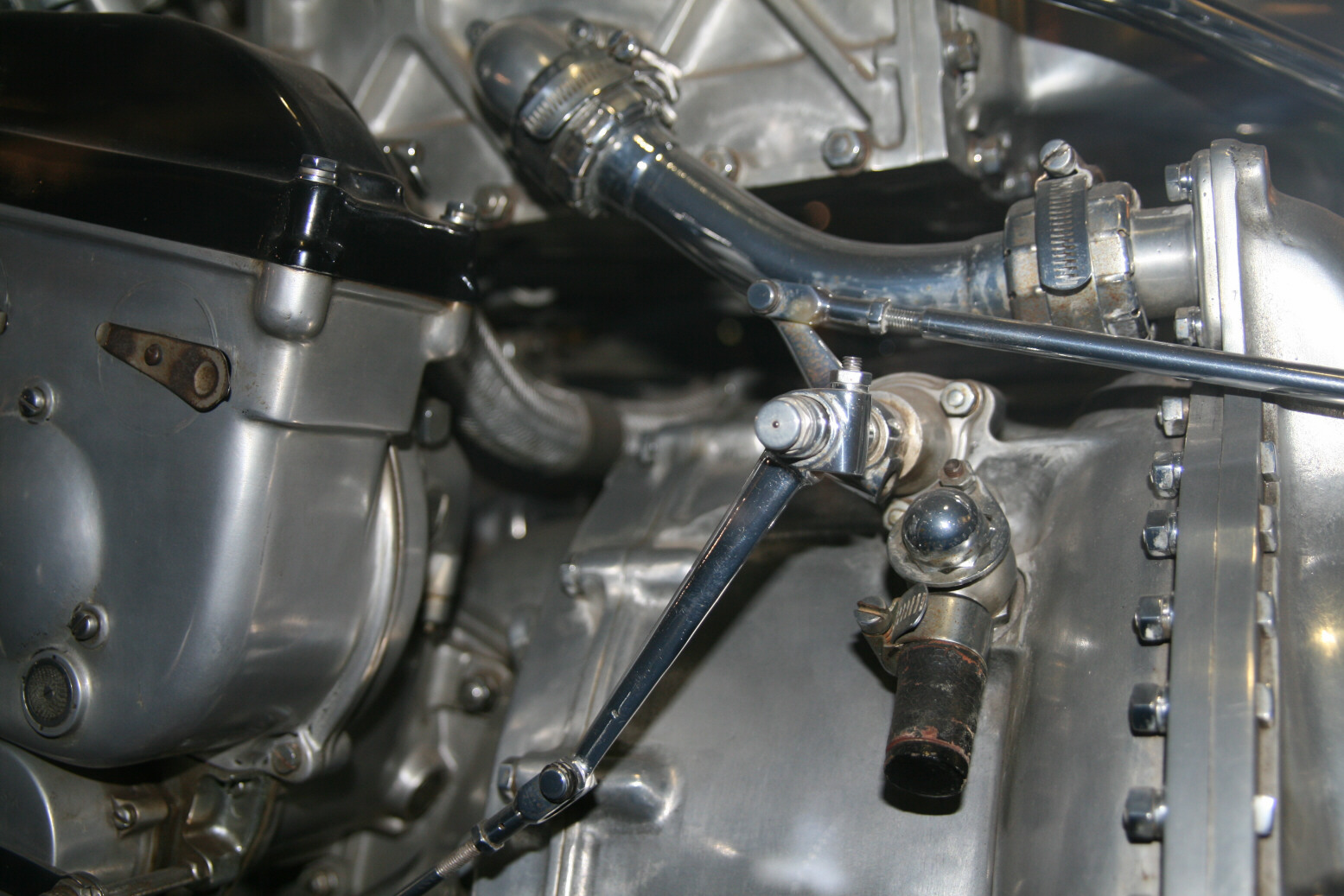
Photos 9 through 11 (below) show the (air) compressor, with underneath it the starboard magneto. Photo 12 (below) shows a close-up of the advance of the starboard magneto (the circular unit below the magneto), with the control rods coming from the left. The vent at the bottom is part of the starter engine. You can also see the bottom of the intercooler (the cube with diagonal reinforcements on the surface) which clearly has the same diagonal reinforcements as the rest.
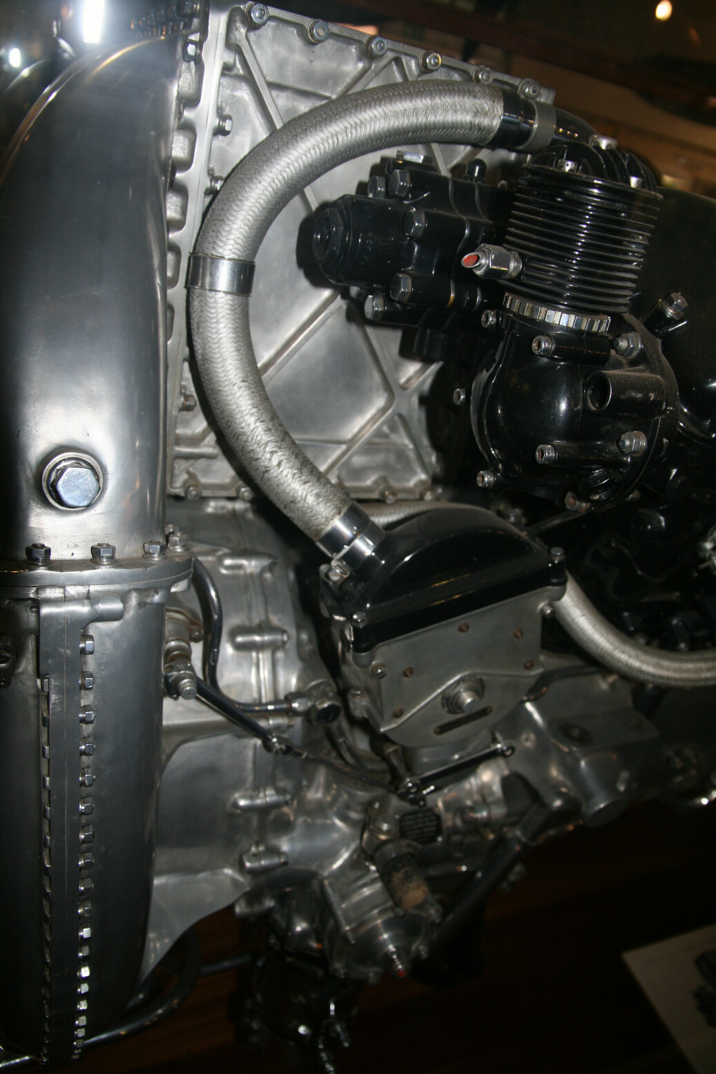
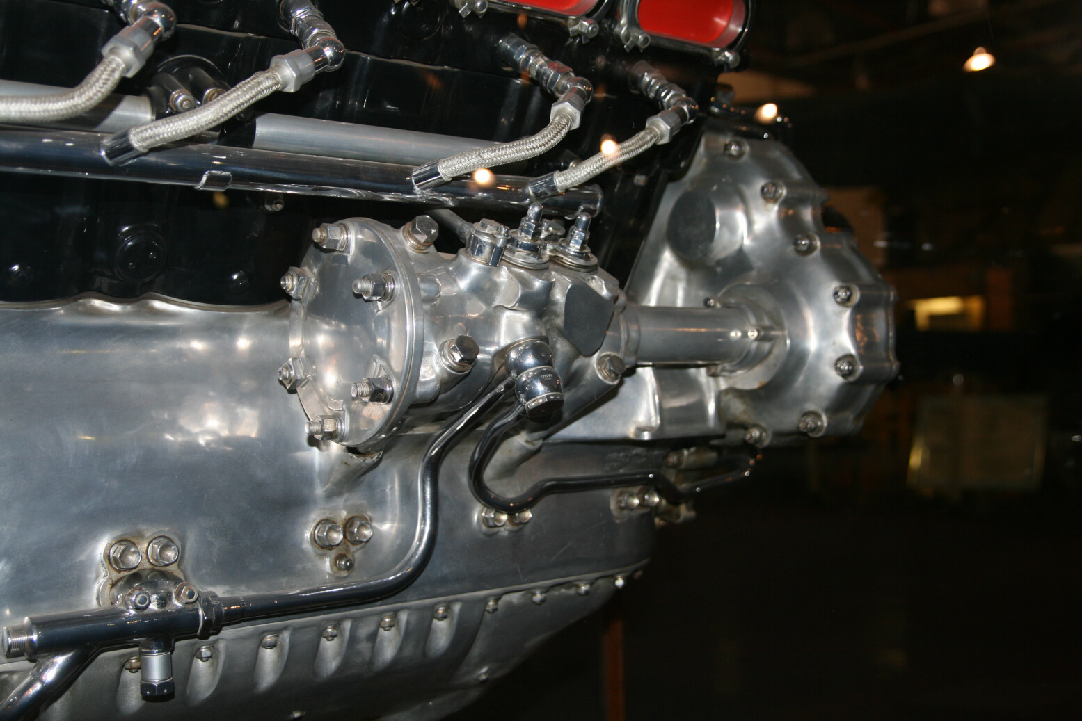
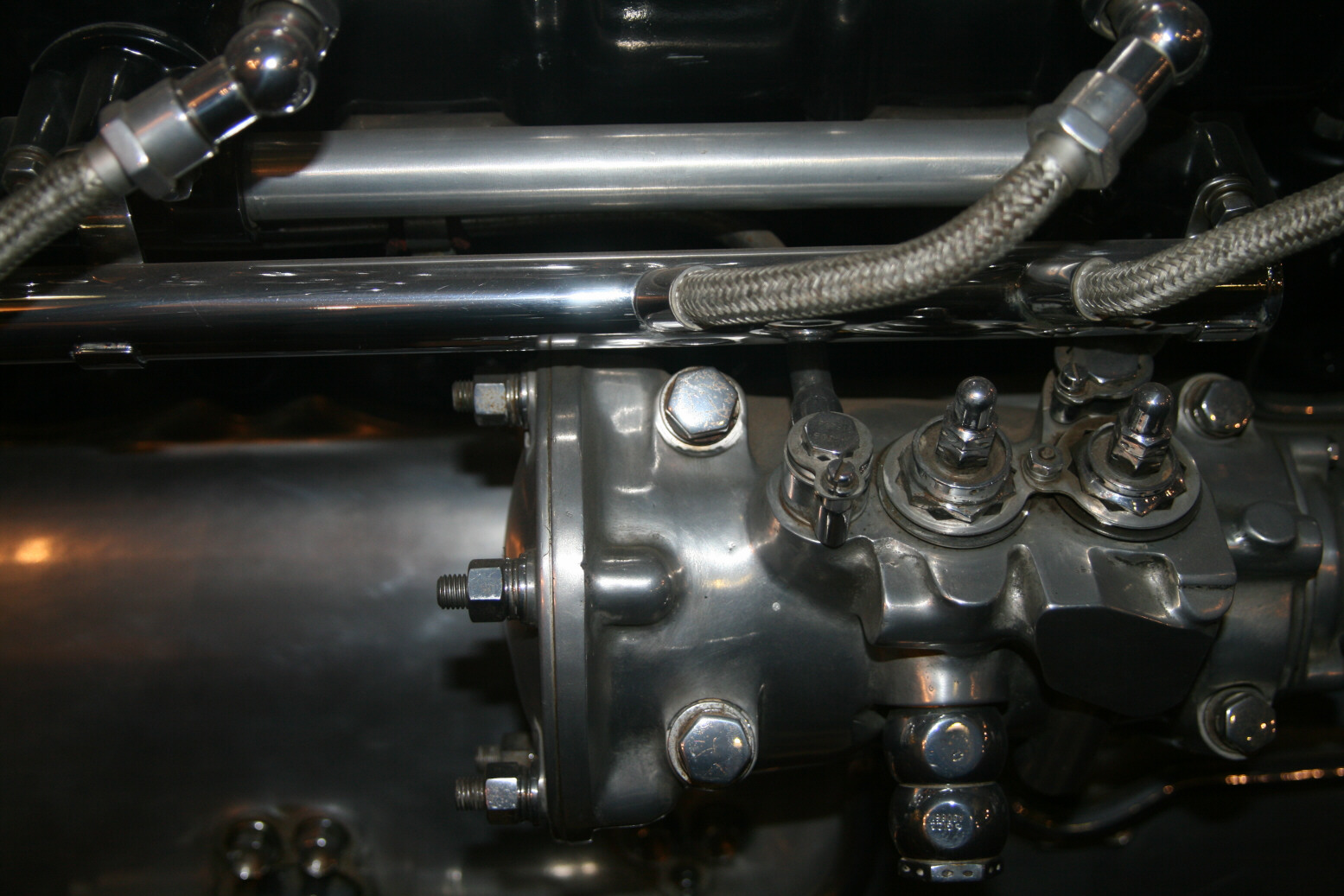
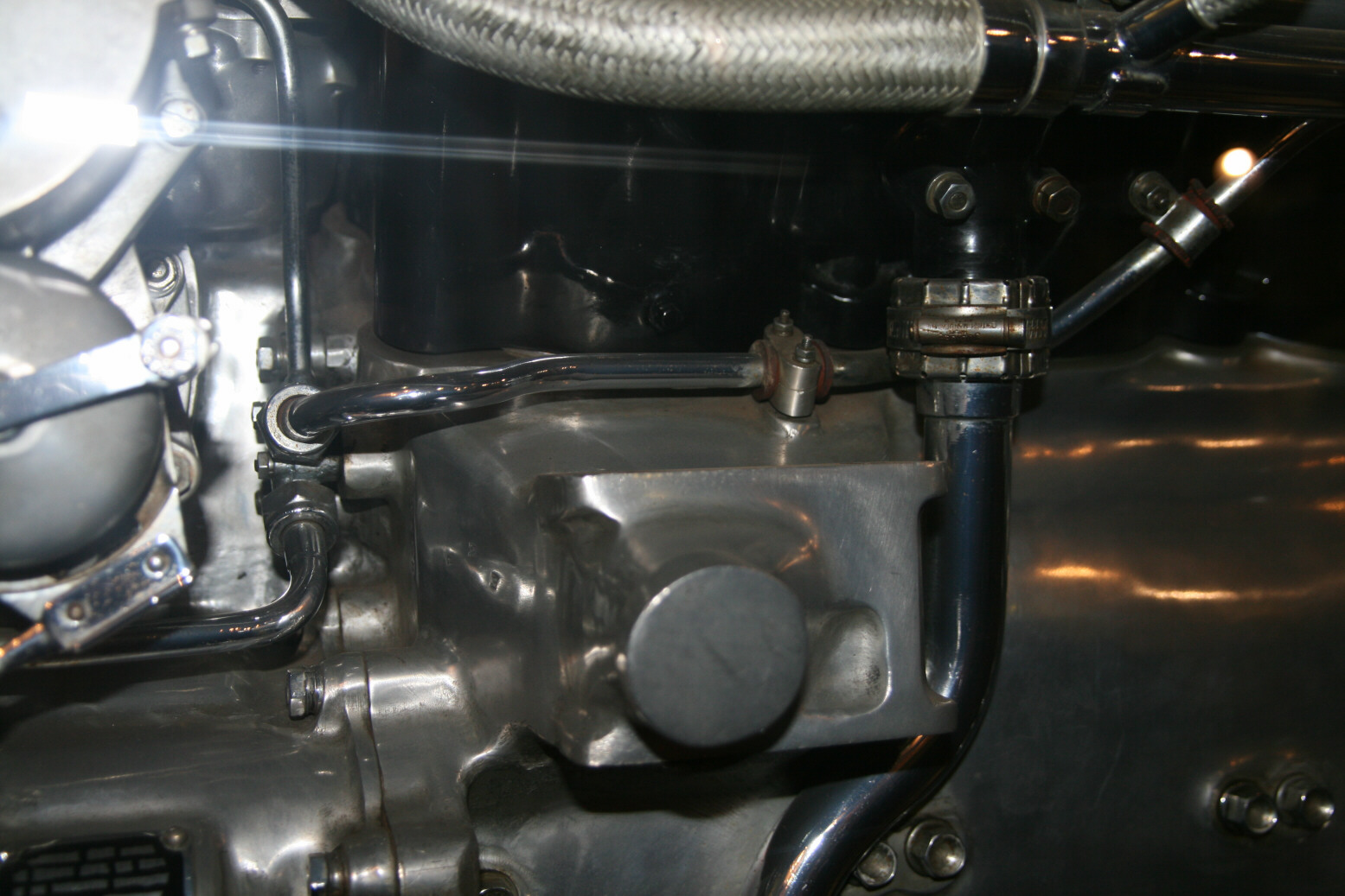
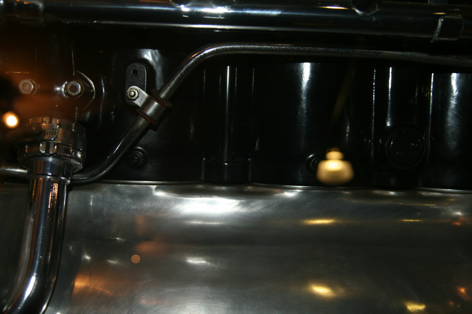
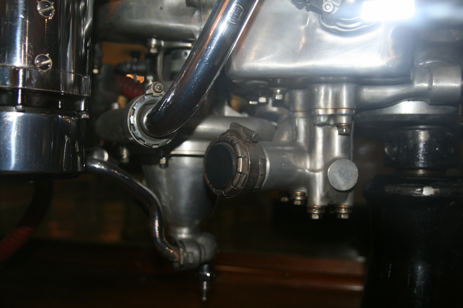
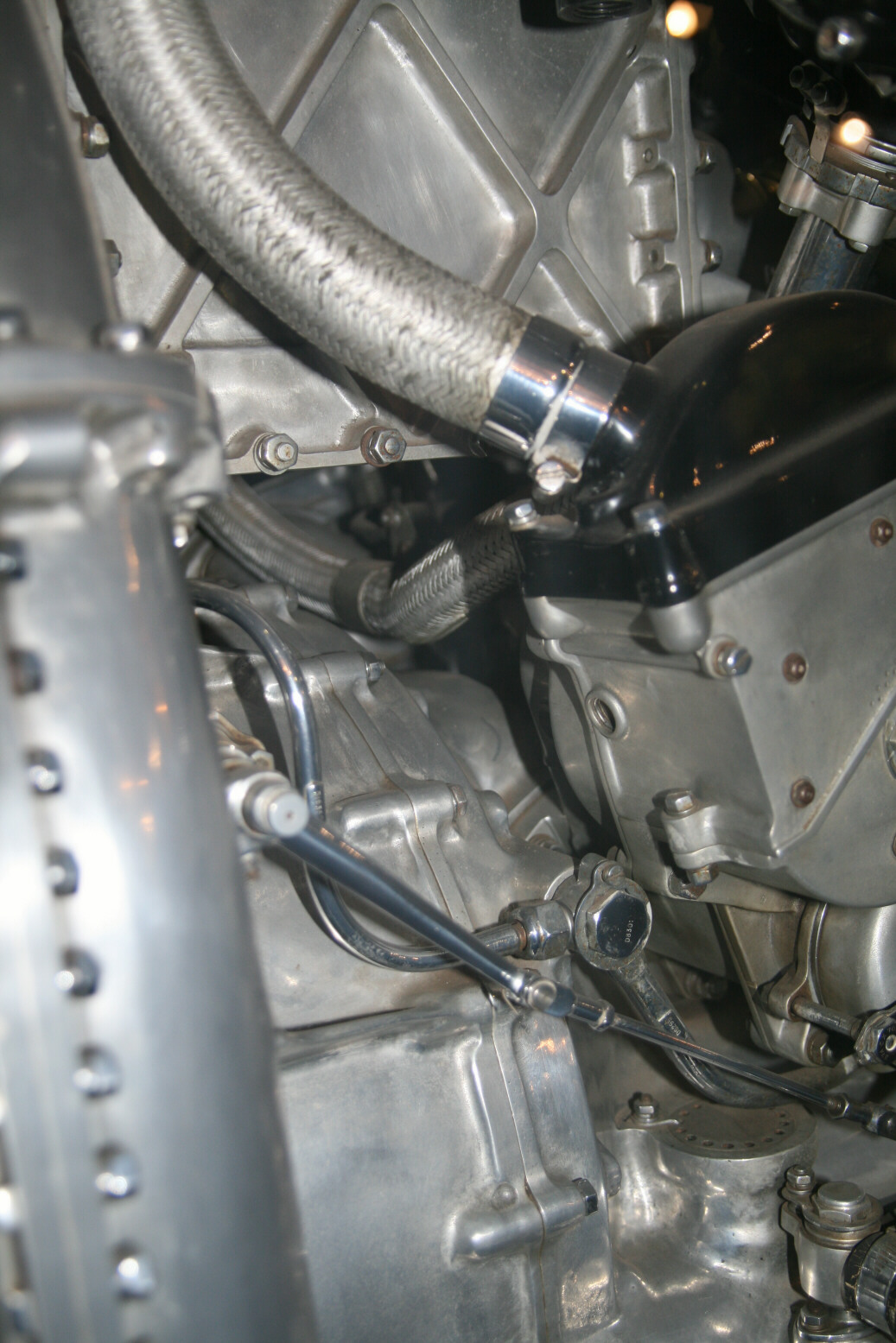
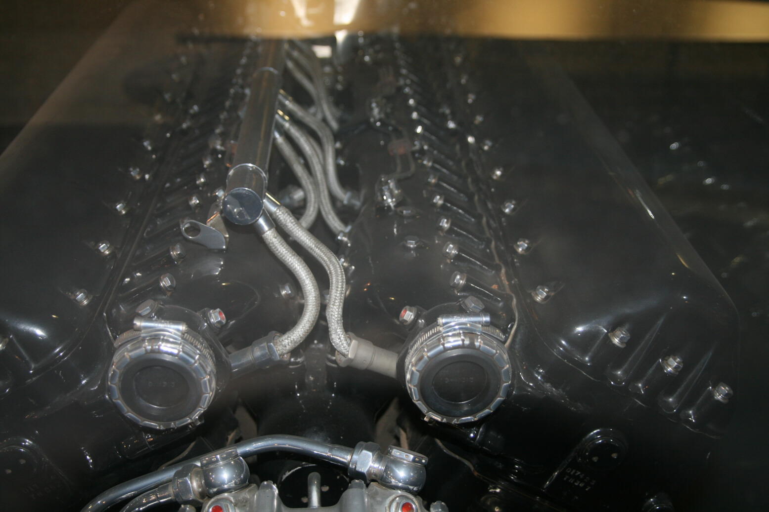
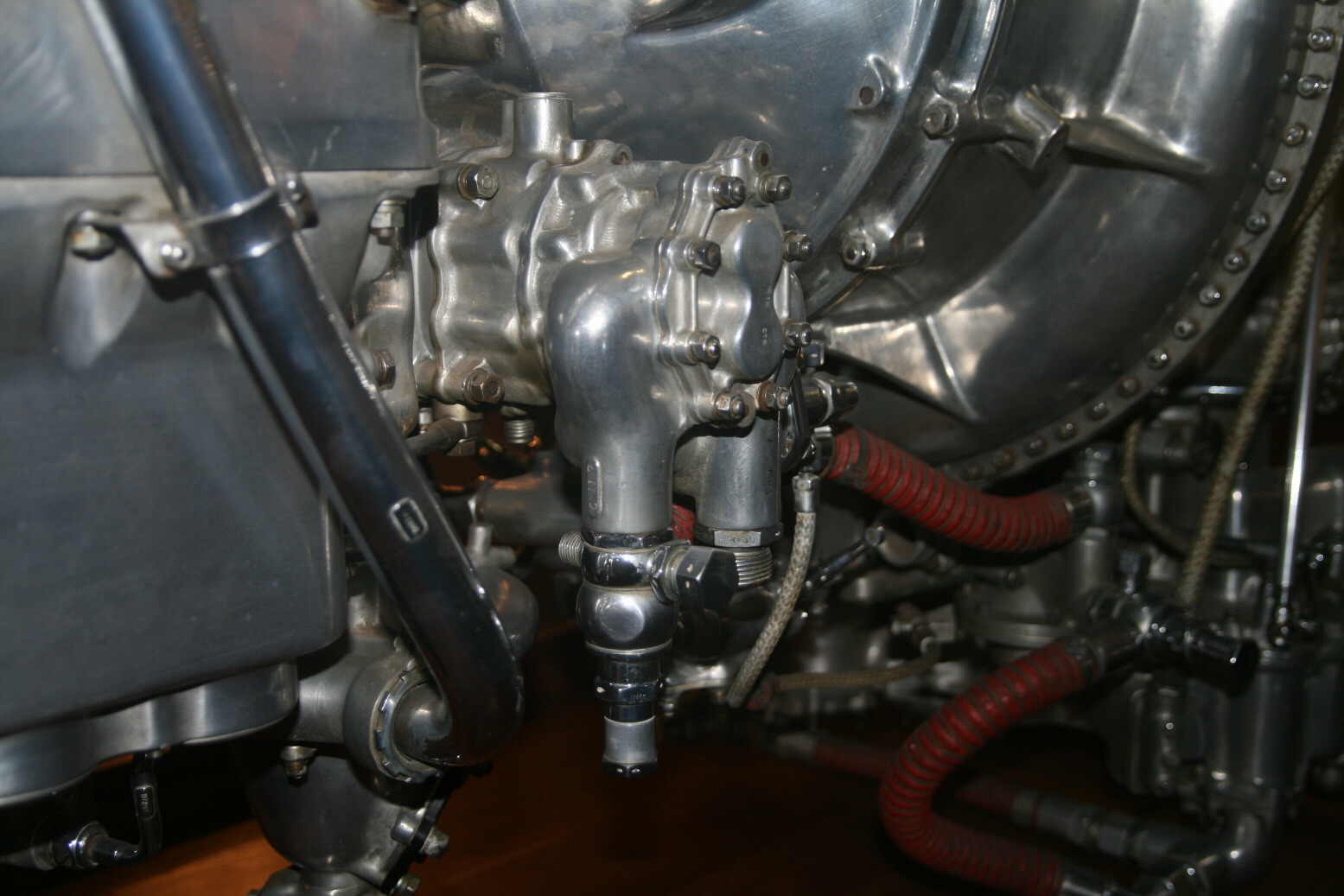
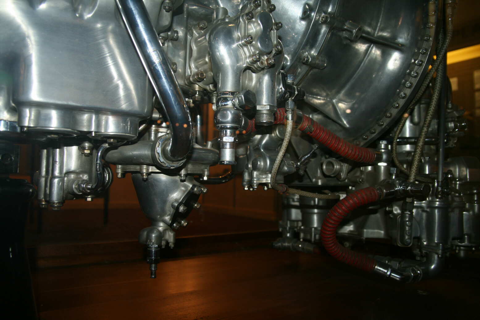
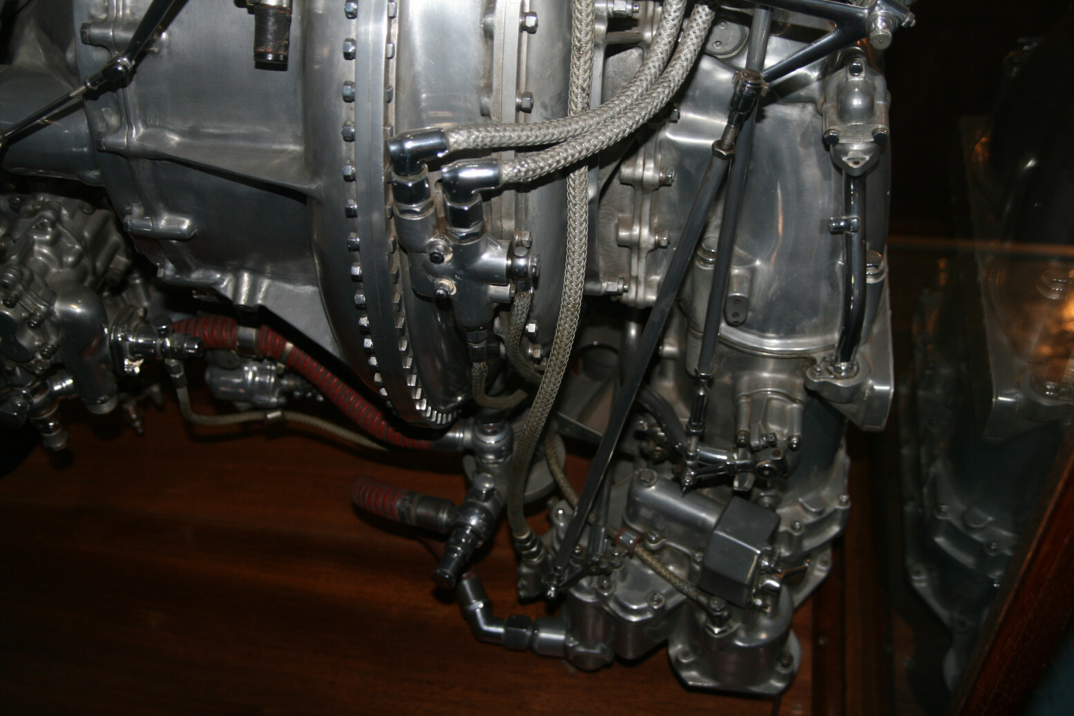
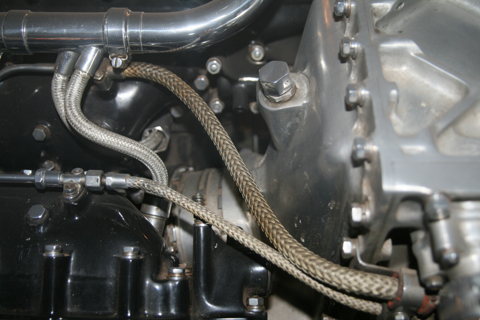
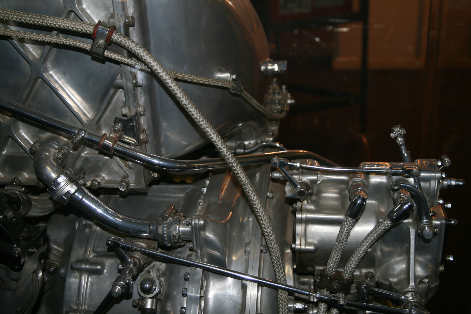
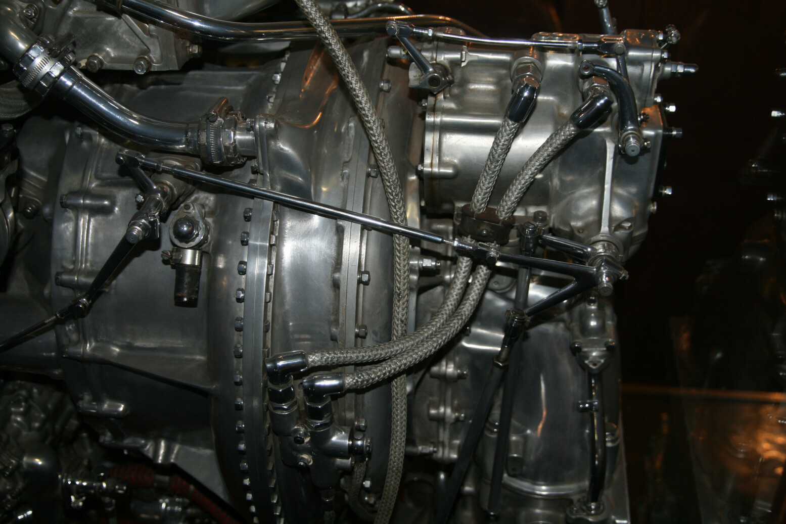
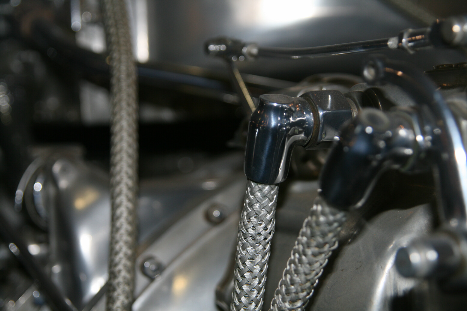
Photos 13 and 14 (below) show an oil line going to a unit whose function I don’t know, but which is connected to the vacuum pump unit up front. Photo 15 (below) shows this unit from the side. Above it is the pipe with the braided ignition cables coming out which go to the spark plugs.
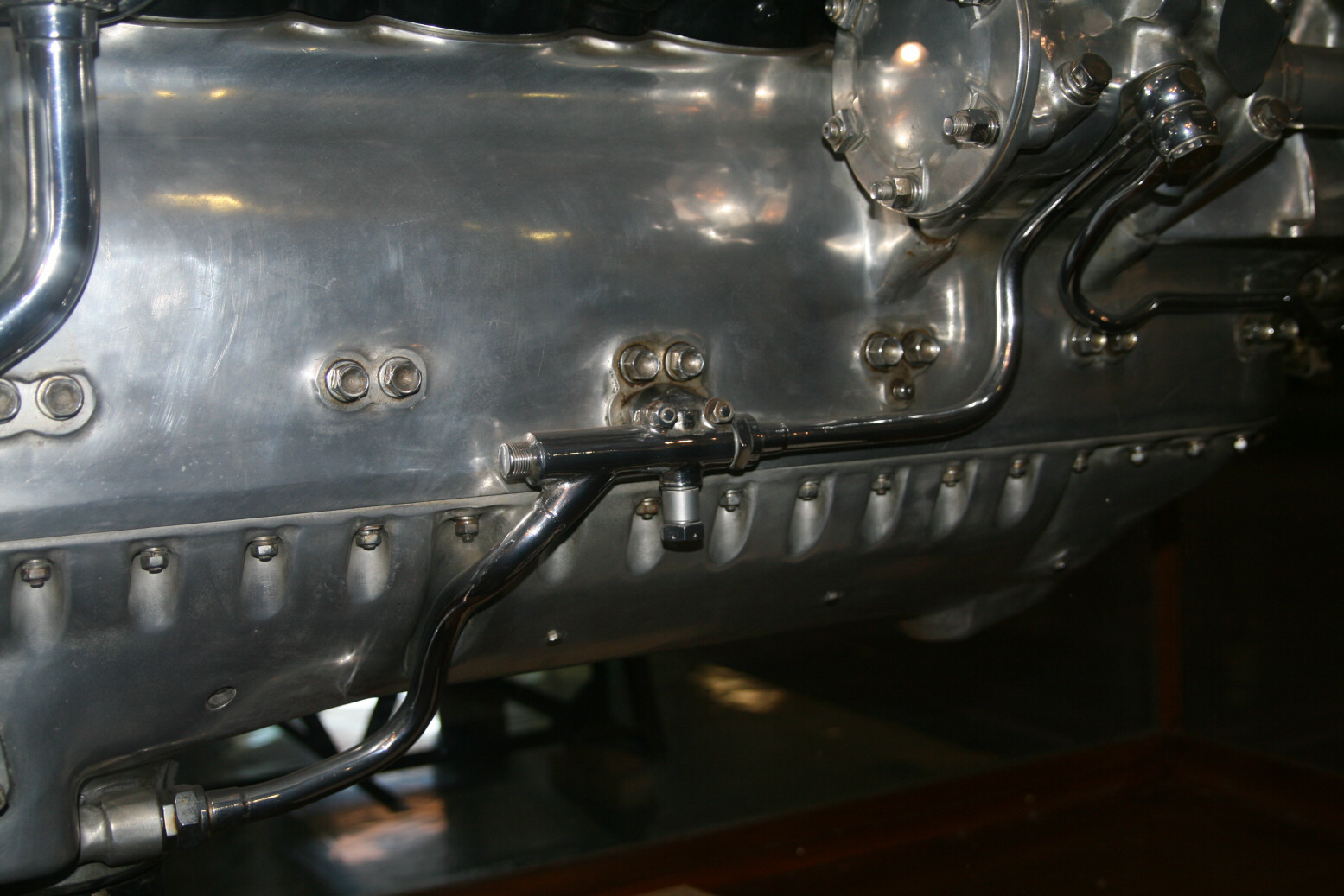
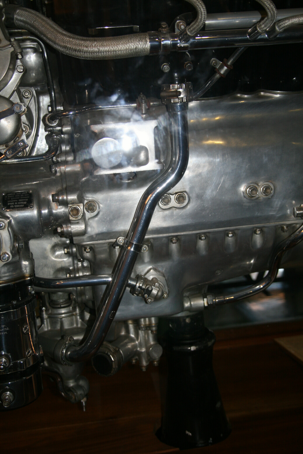
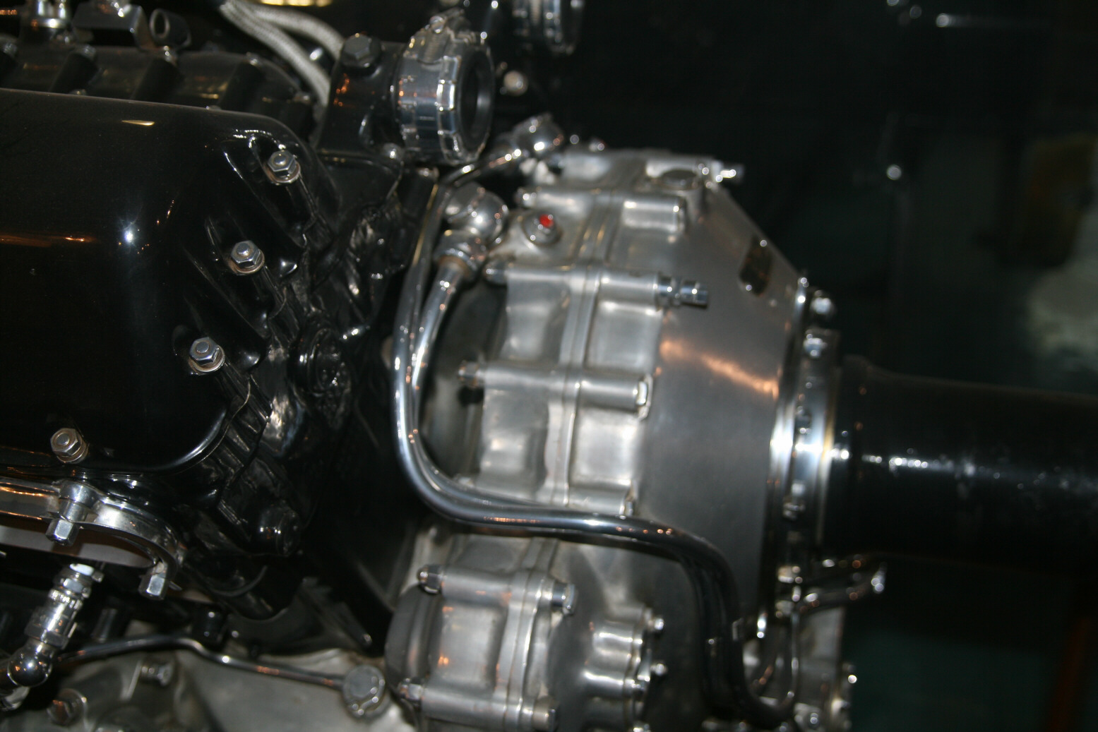
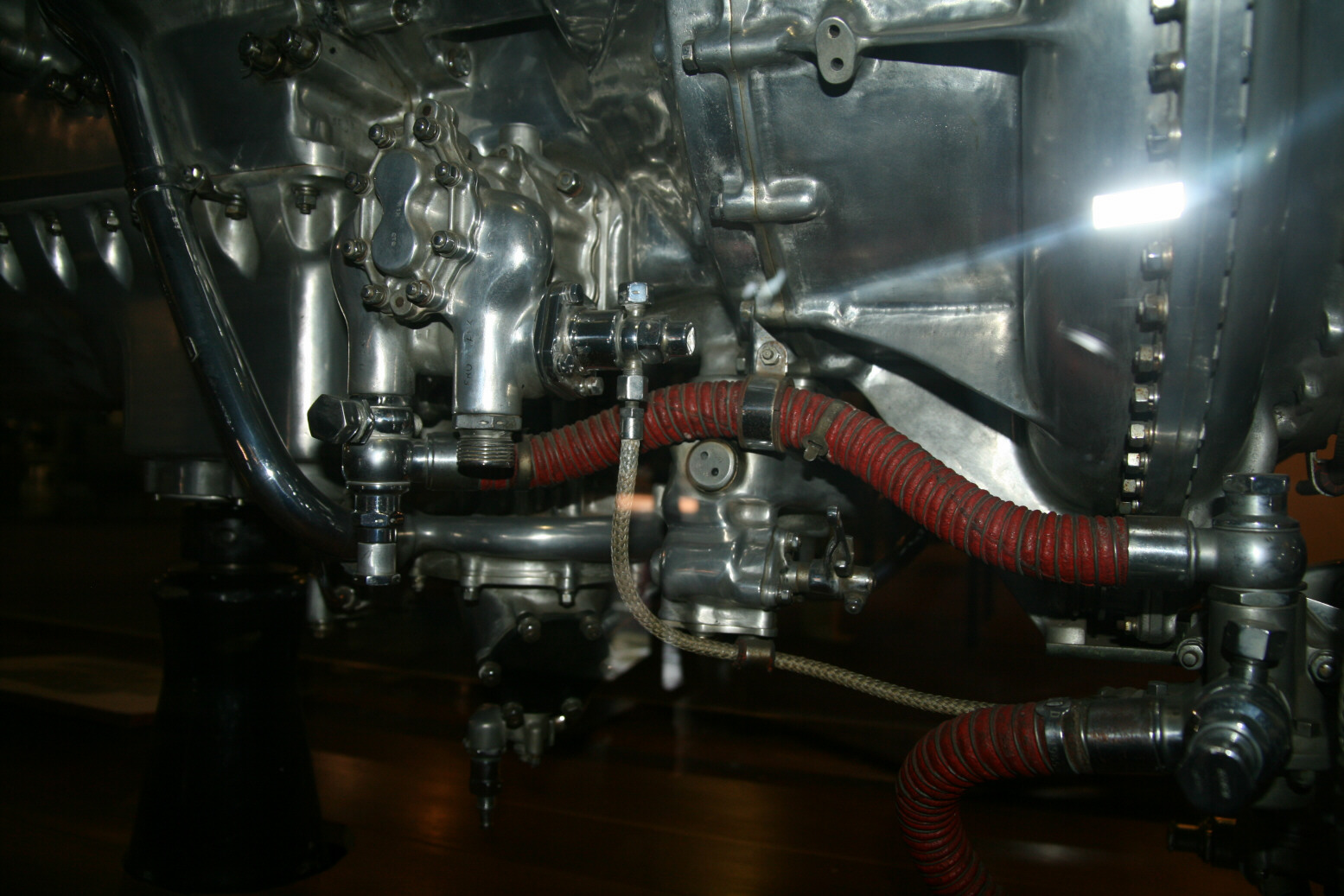
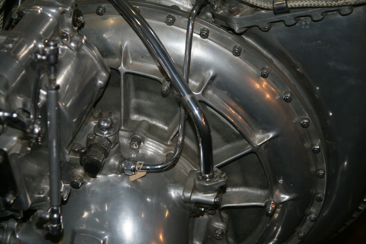
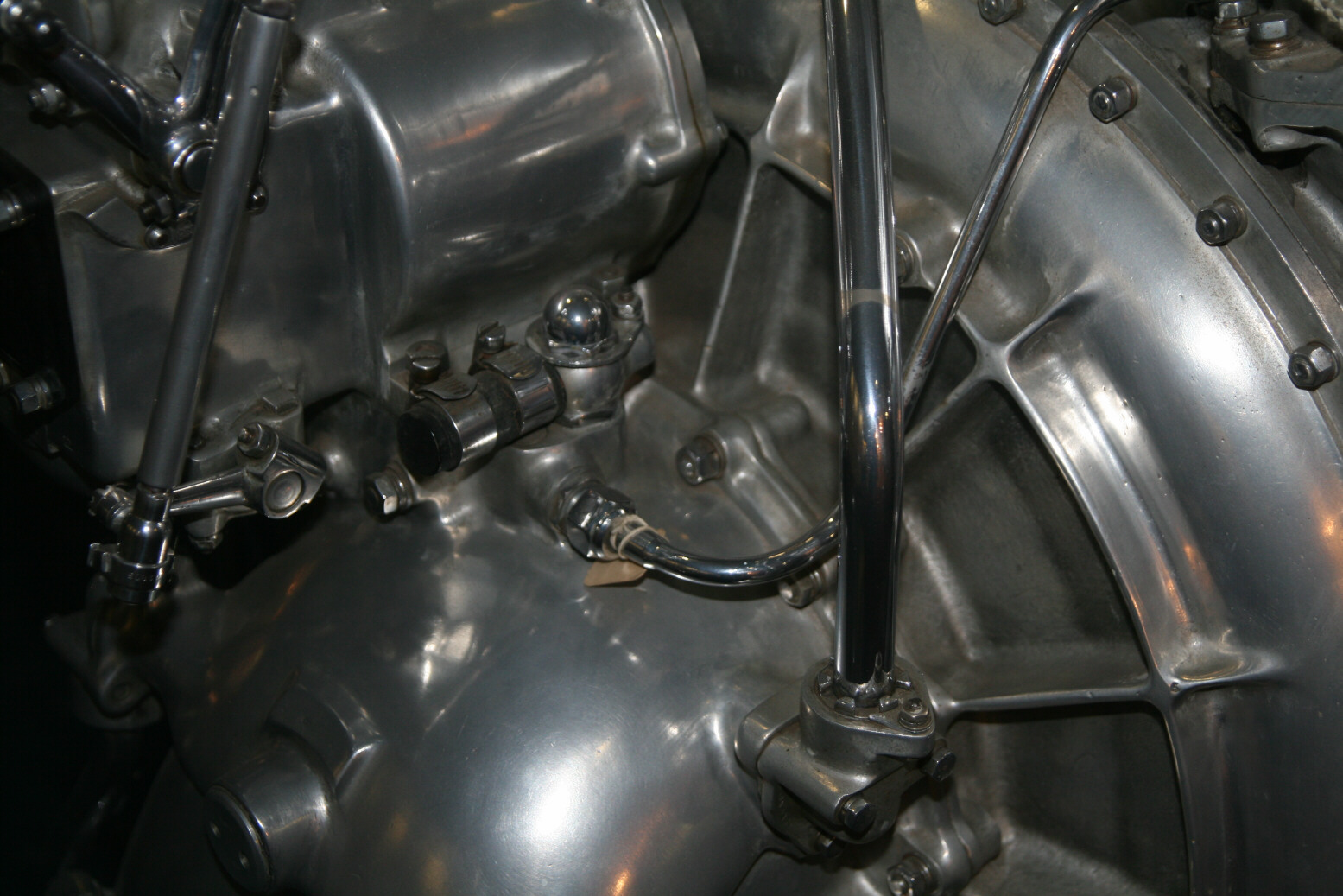
Photos 16 through 19 (below) show the cooling fluid pipe that goes from the pump at the bottom to the cylinders. A similar, mirrored pipe is on the port side.
Photos 20 and 21 (below) show detail above and behind the magneto. In photo 20 you see that there is a gap between the intercooler and the supercharger connection through which one ignition cable goes (this is the cable that comes from the port magneto which controls on both sides the outer spark plugs – so the cable you see on either side of the magneto continues on behind the magneto and is not connected to it). The starboard magneto has but a single cable coming out and that one goes to the top and controls the inner spark plugs.
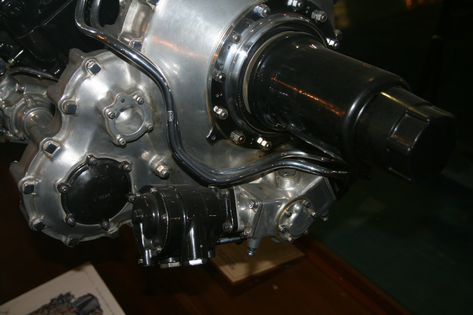
Next we proceed to the front of the engine. Photo 22 (below) shows the top of the reduction gear housing, with photo 23 (below) showing the bottom, with the vacuum pump unit. The propeller shaft either has cap over it or somebody removed the grooves that should be there. Photo 24 (below) shows a view along the top. In the centre you see the end of the ignition cables, going to the frontmost inner spark plugs. The two circular caps are on the exit pipes of the cooling system. Normally these would be connected via two short pipes to the coolant header tank just in front of it. Photo 25 (below) shows the same area but more from the top.
Photos 26 through 28 (below) proceed to the port side of the reduction gear. Note the blanked-off pipe.
Photos 29 through 32 (below) show the generator (the two capped pipes up front are for cooling air intake). In photo 32 you also see the bottom of the port magneto with the advance.
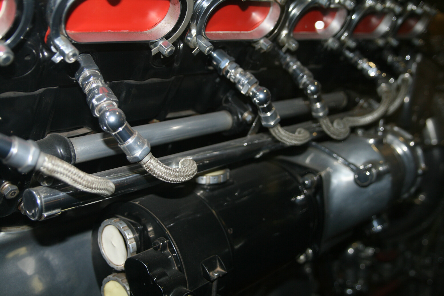
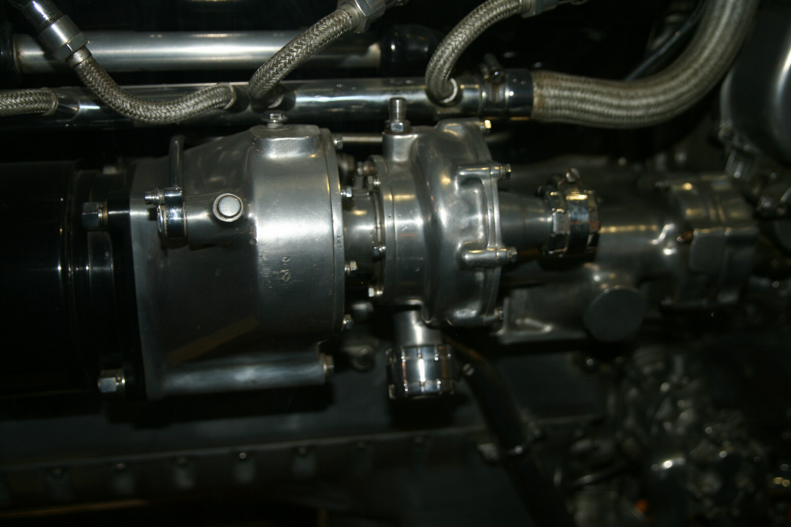
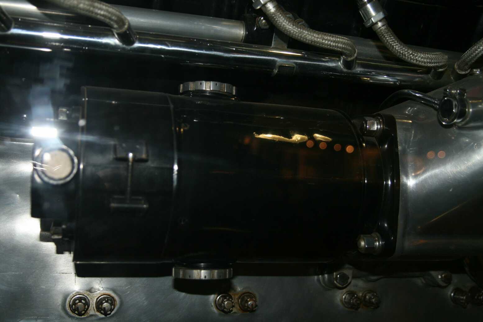
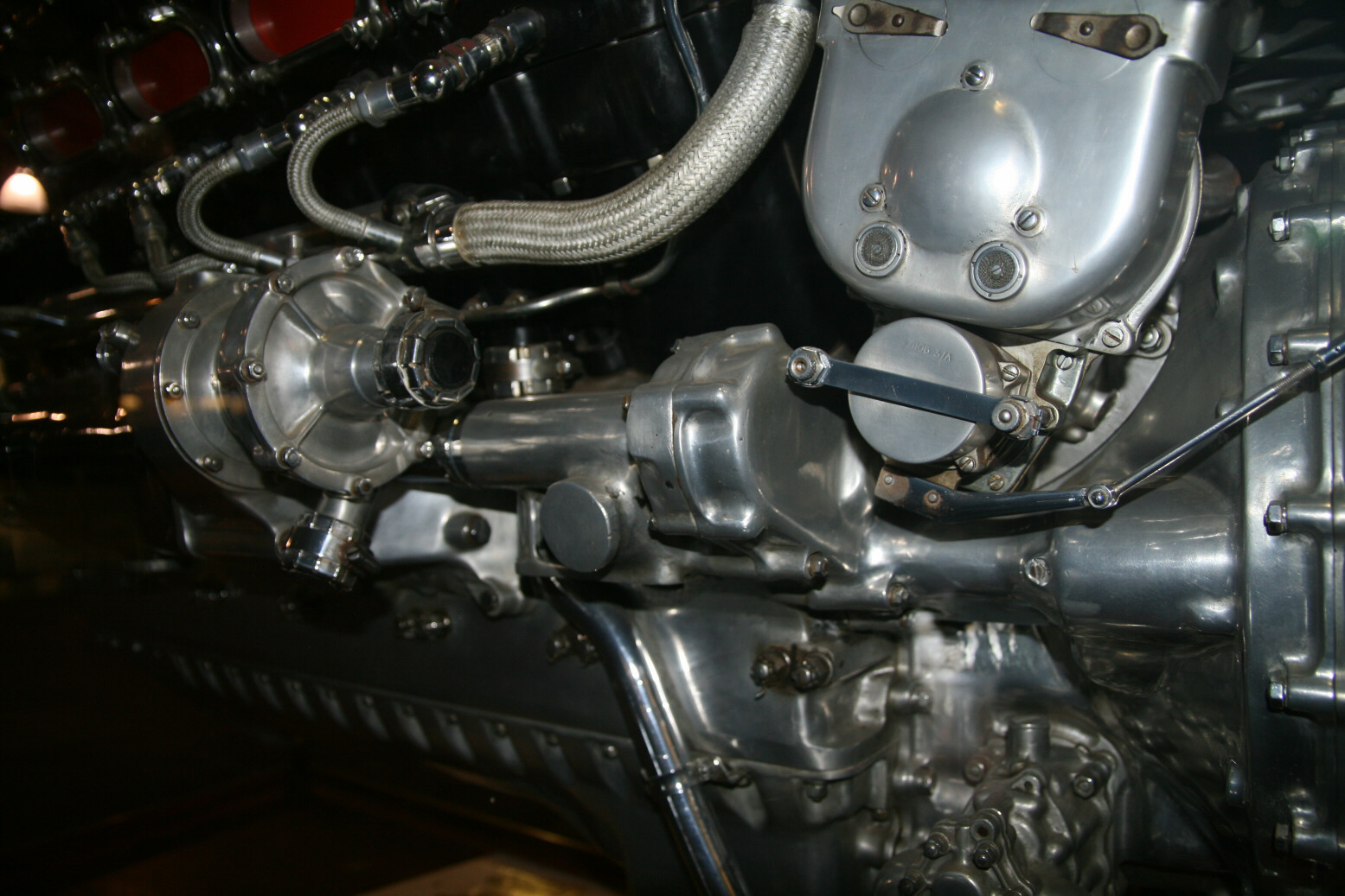
Photo 33 (below) shows the oil sump on the left (just to the right of the black pillar on which the engine is standing). Further back is the cooling fluid pump with the pipe coming out of that which goes to the cylinders. The blanked off connection, seen almost edge-on near the bottom, is where the pipe coming from the radiators would be connected to.
Photos 34 through 42 (below) show the fuel pump and the port carburetor from various angles. The fuel pump is the ‘inverted horse shoe’ unit to which the horizontal red pipe is connected. The fuel intake pipe (coming from the fuel tanks) would be connected to the other (front) part of the horse shoe.
Photos 43 through 49 (below) show the air intake part of the supercharger at various angles. Photo 44 shows a unit mounted on the supercharger. I’m not sure but it is a bit like the oil connection unit that on other engines is on the port side and which contains the oil gauge. Photo 46 shows the back part of the magneto advance. On older Merlins this would be connected to a lay shaft that in turn is connected to the control lay shaft on the firewall behind the engine, but I suspect this particular unit is automatically controlled. The control connections on the back are not at all obvious (photo 47). Photo 50 (below) is at a rather odd angle but it shows the boost control from the top. This definitely is automatic and no longer controlled directly by the pilot.
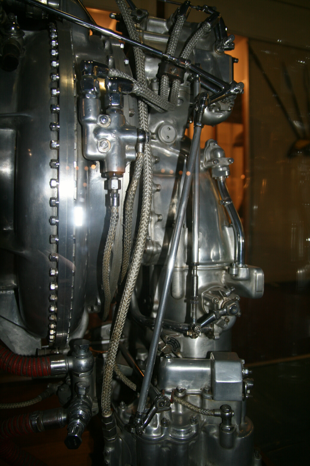
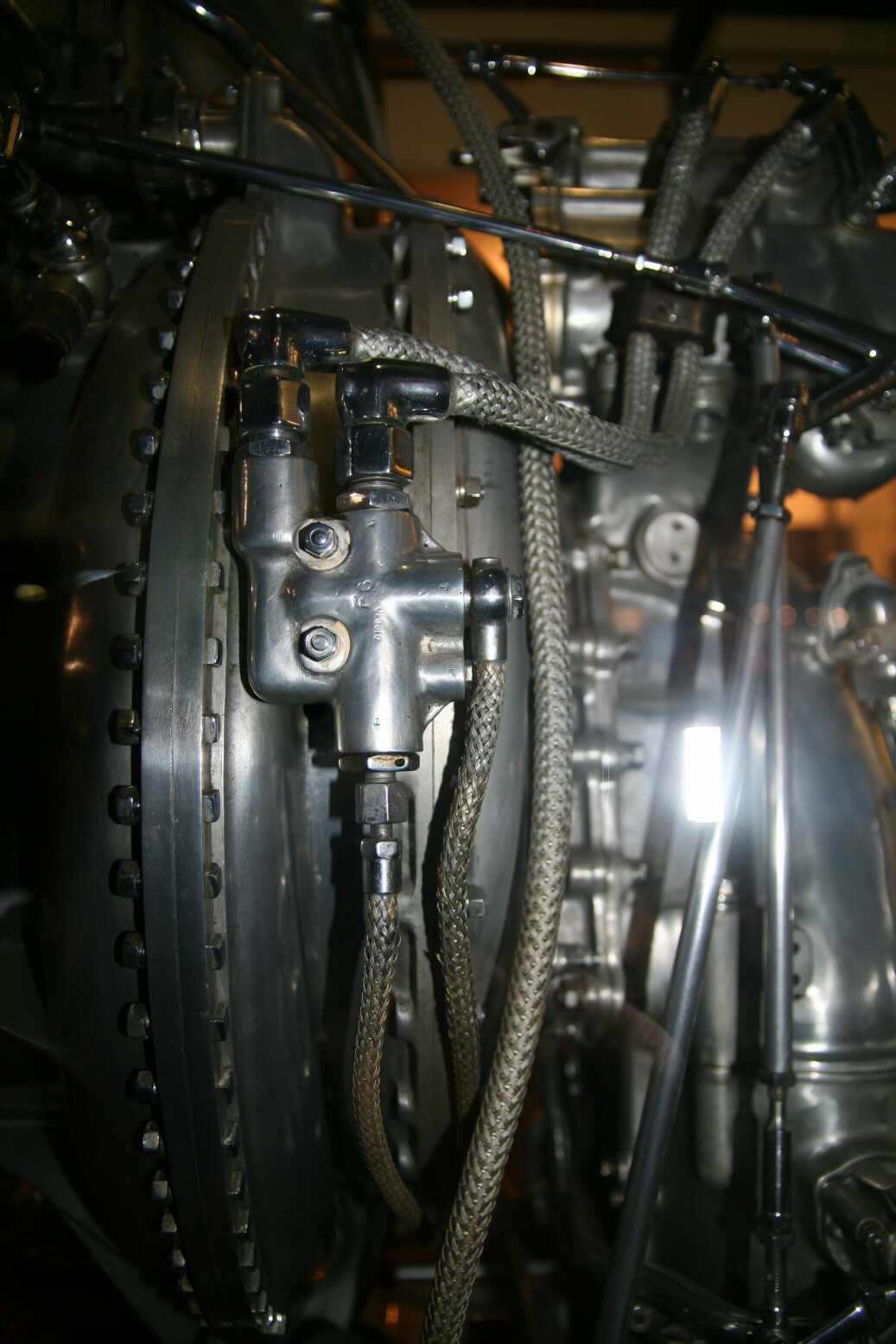
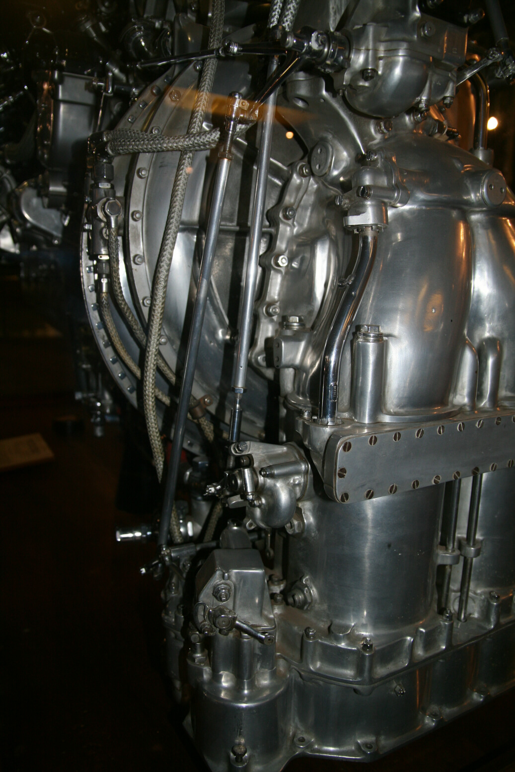
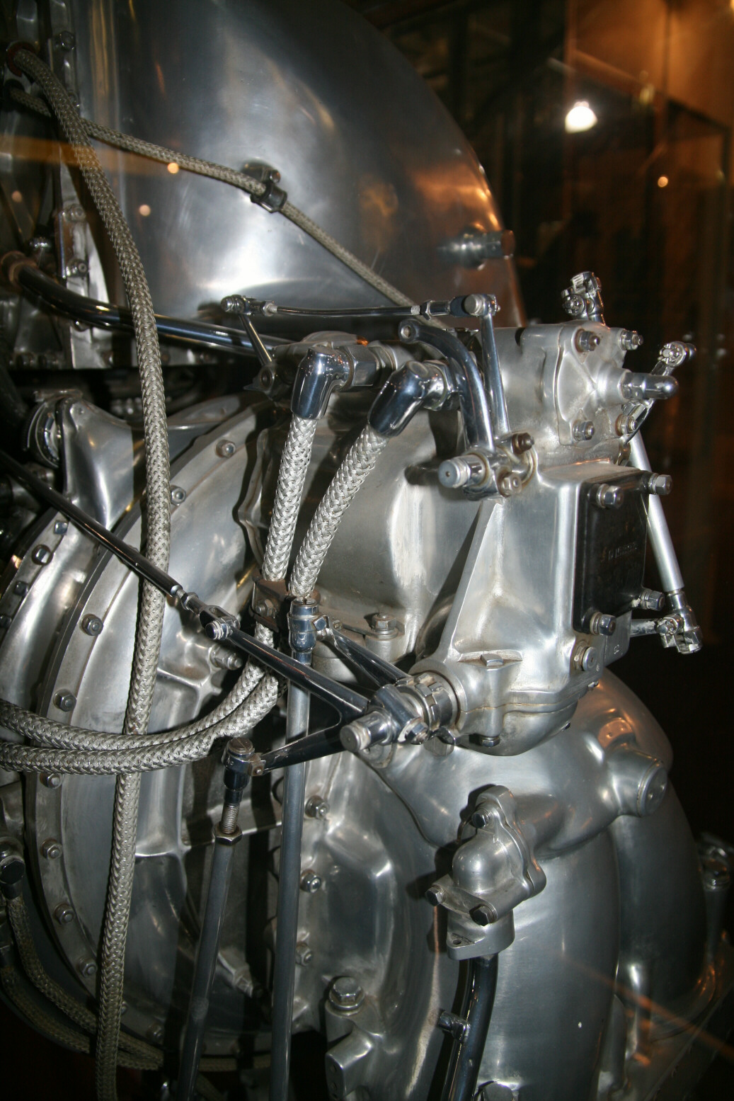
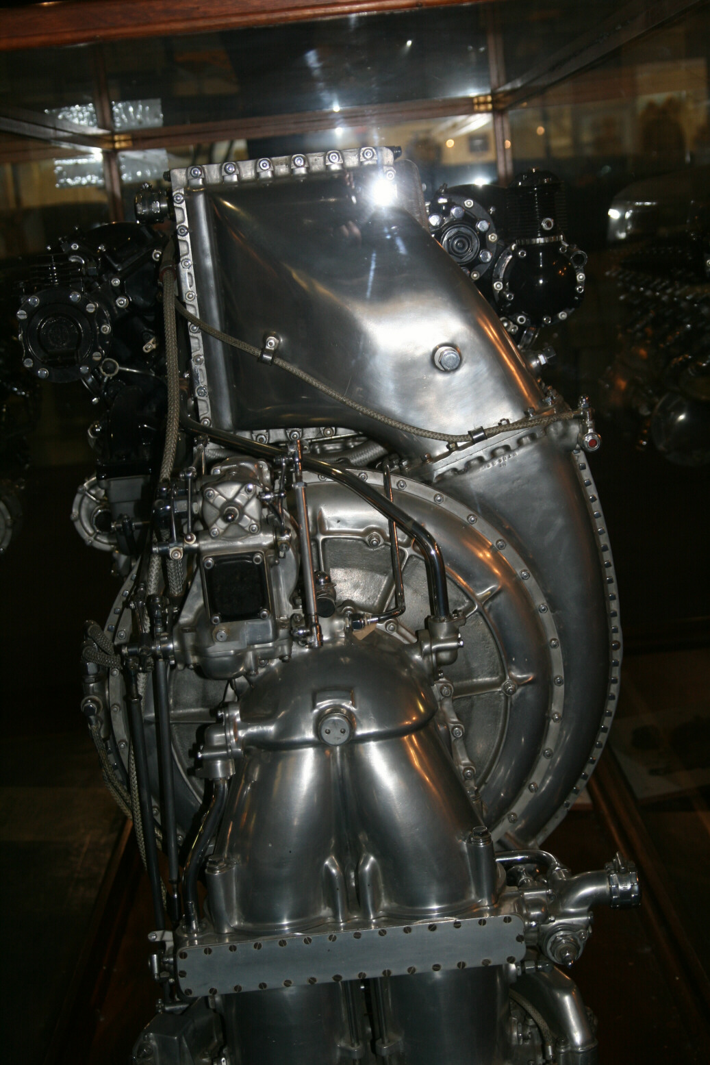
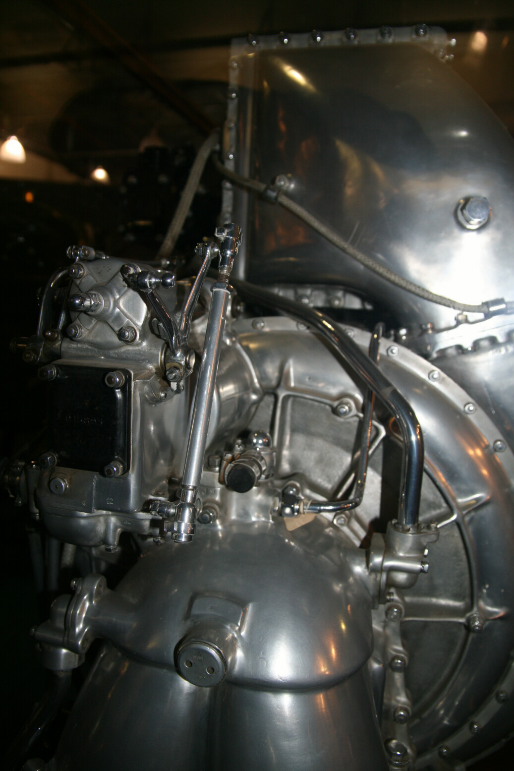
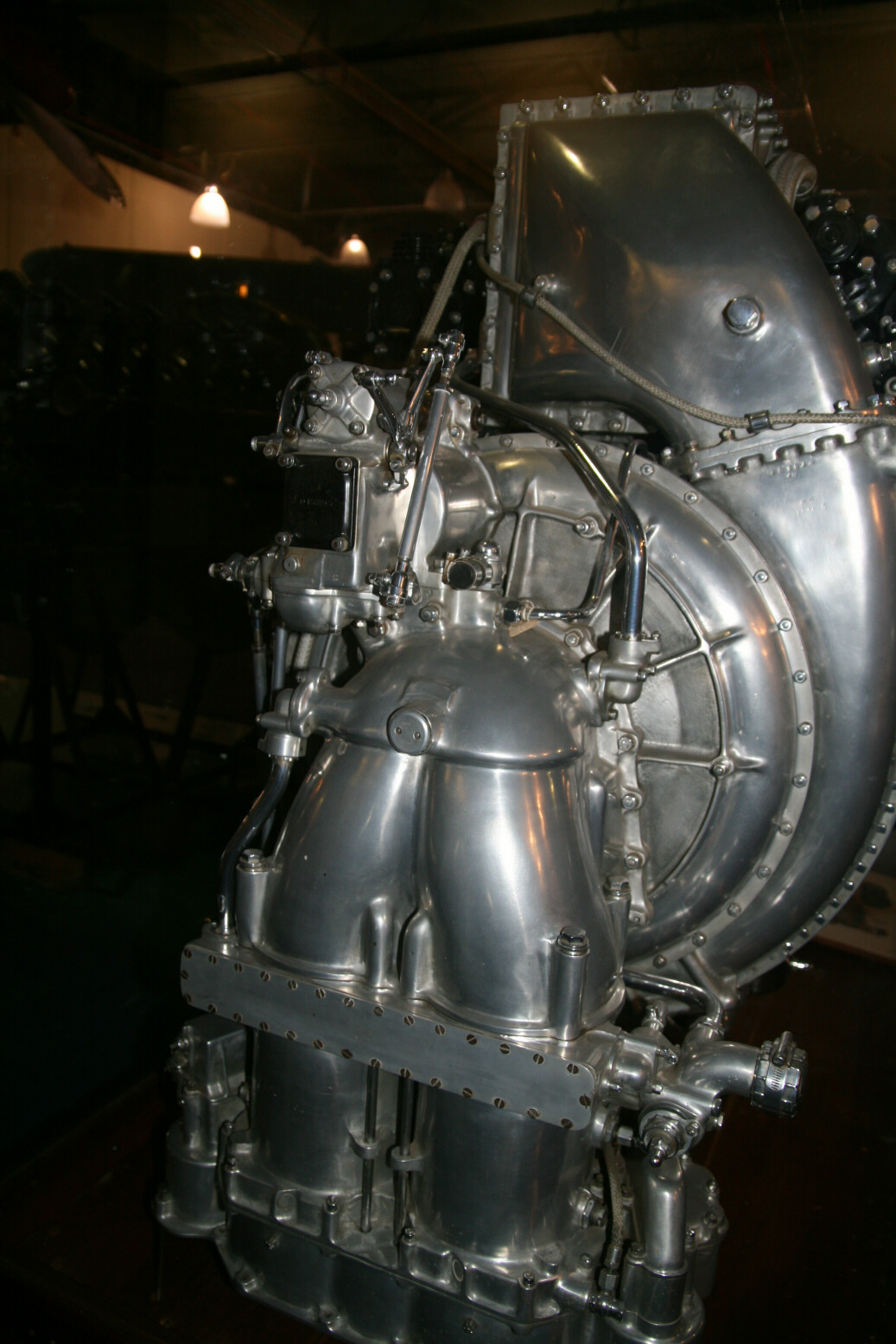
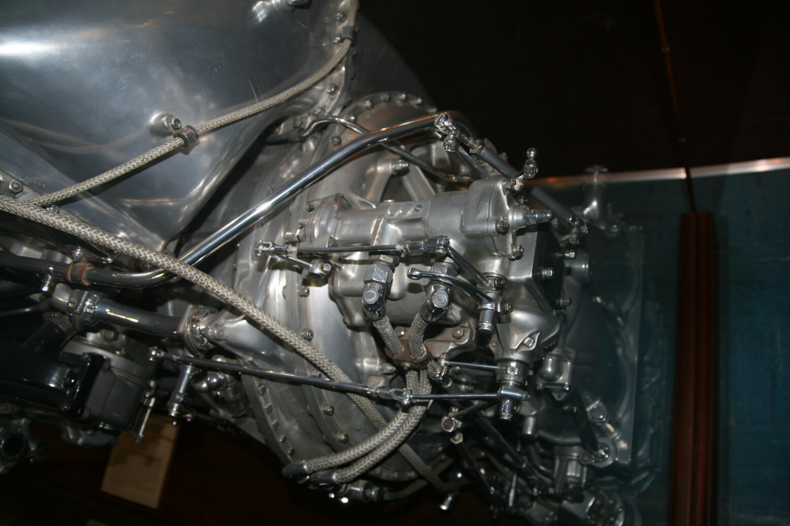
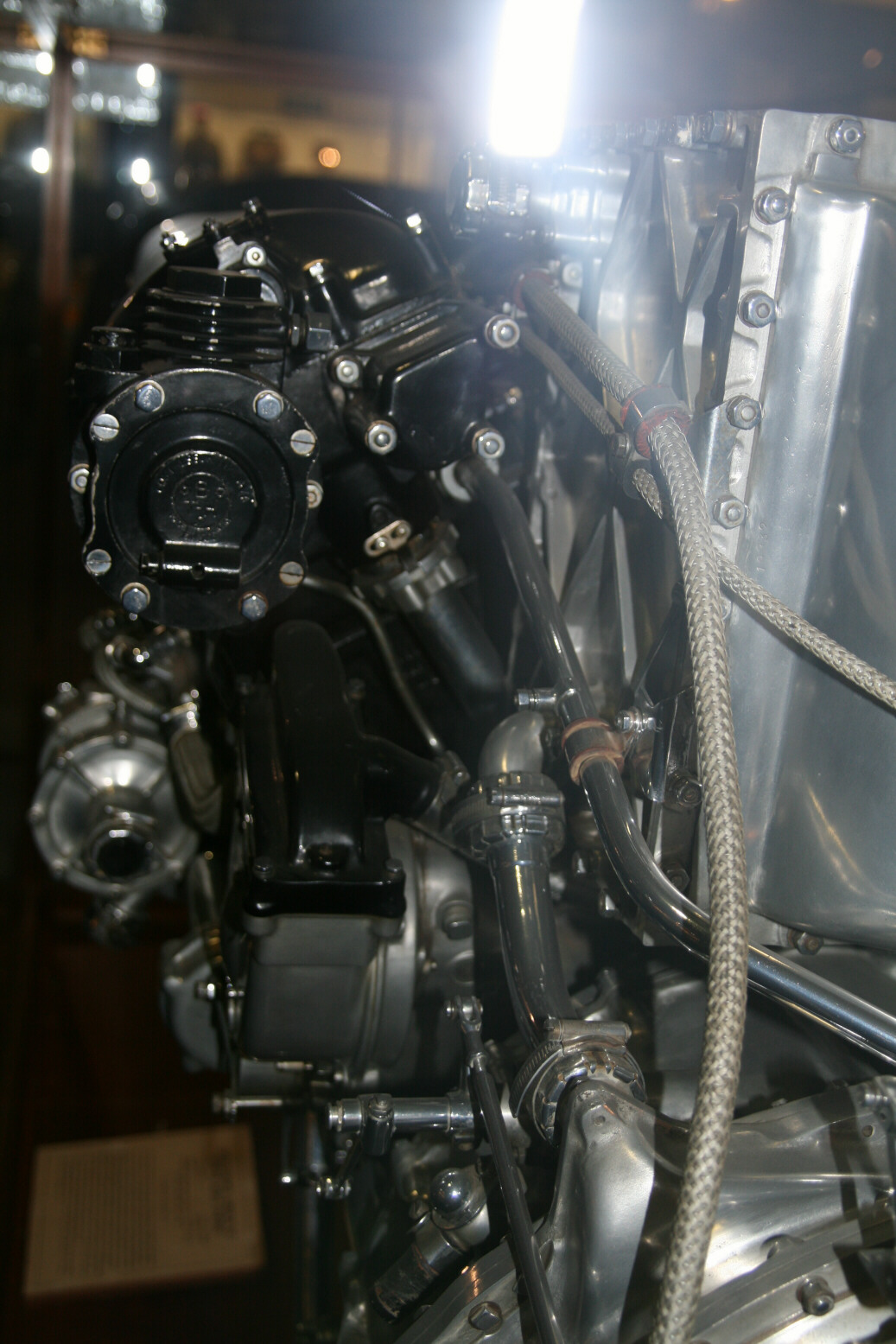
Photo 51 (below) is viewing directly along the engine to the front. On older engines the black circular plate on the end would have the connection (through a Bowden cable) to the rpm gauge on the instrument panel, but here it doesn’t seem to have anything at all. Photo 52 (below) shows the top of it, with the intercooler housing in the background. Photo 53 (below) is even messier. You are looking down onto the port magneto (black cap) from an angle. You can see the cable exiting at its back, which is the cable for the starboard outer spark plugs. The unit on the right is the intercooler housing with its diagonal reinforcement ribs.
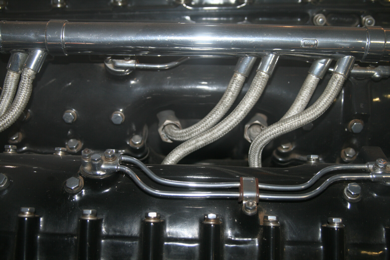
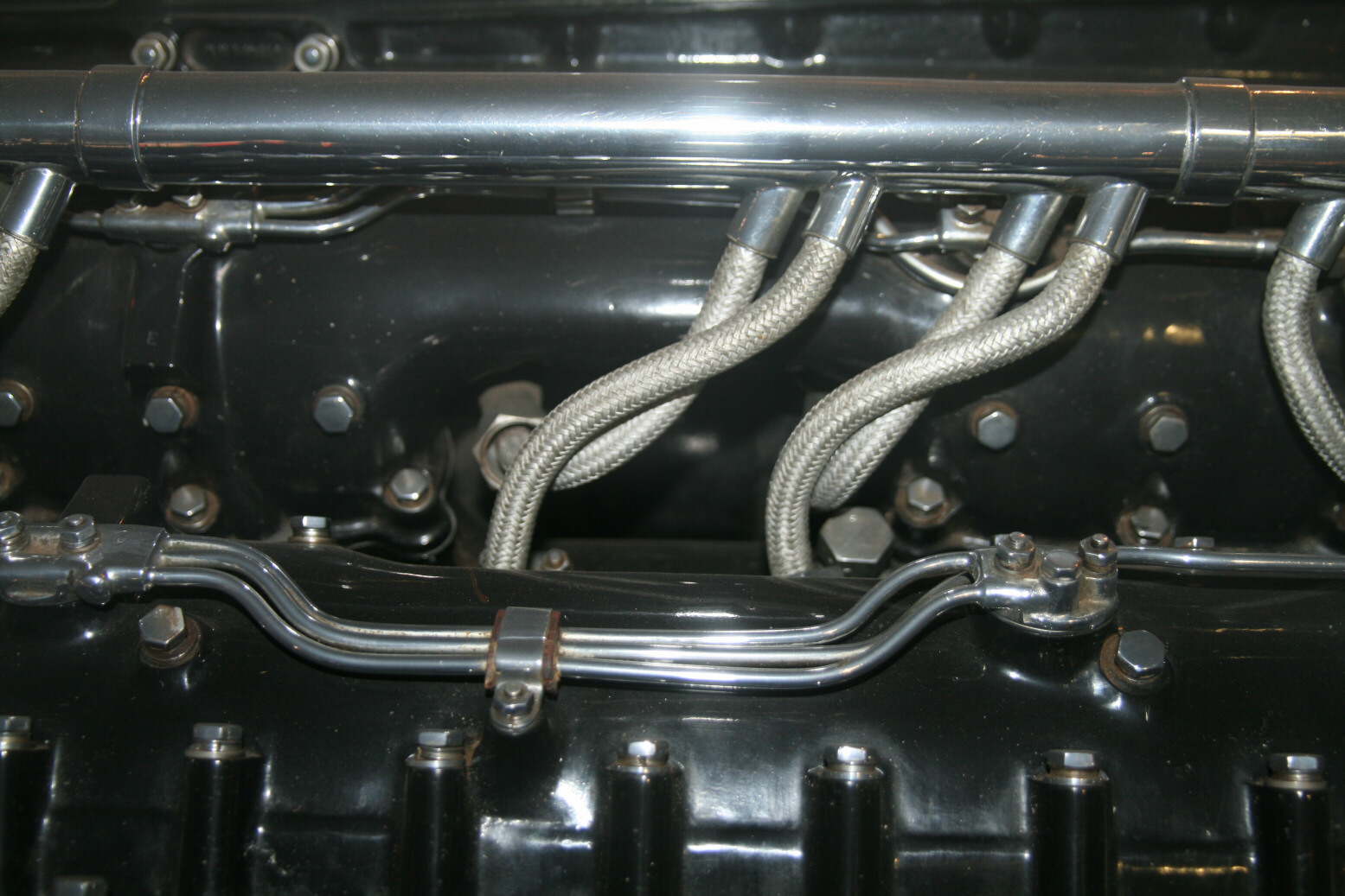
Next, front to back a series of photos of the top (54 through 57, below) showing ignition cables and oil lines, ending at the top of the intercooler housing. Photos 58 and 59 (below) are further back, showing the top of the supercharger from the port side.
Photos 60 and 61 (below) show the control rods of the magneto advance in more detail. Photo 62 shows the ? oil connection lines (the unit seen in photo 44) from the top.
Finally photos 62 through 67 (below) show the air intake part of the supercharge from various angles.
© Max Otten 2015
This article created on Saturday, June 20 2015; Last modified on Thursday, March 31 2016