
Revell 1/28 Fokker Dr. I
By Martin Gastel
Revell 1/28 Fokker Dr. I
Die Optische Täuschung (The Optical Illusion)
by Martin Gastel
Photos by Martin Gastel & Steve Bamford
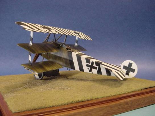
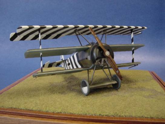
This model represents the Fokker Dr. I 586/17 (Works No. 2256) flown by Ltn. Hans Kirschstein when acting CO of Jagdstaffel 6, a part of Jagdgeschwader Nr. 1 Richthofen. Kirschstein joined this unit in March 1918 and became acting CO on April 27. Between 7 and 15 May he temporarily commanded Jasta 4 where he left this aircraft as Jasta 6 had begun conversion to the Fokker D. VII. This aircraft was then taken over by Ltn. Ernst Udet, who went on to become Germany's highest scoring surviving ace of WW I with 62 victories.
On 16 July 1918, Kirschstein was killed in an accident involving a Hannover two-seater aircraft in which he was the passenger. At the time of his death, he had achieved 27 victories and had been awarded Germany's highest military award, the Orden Pour le Mérite, all in less than four months at the front!
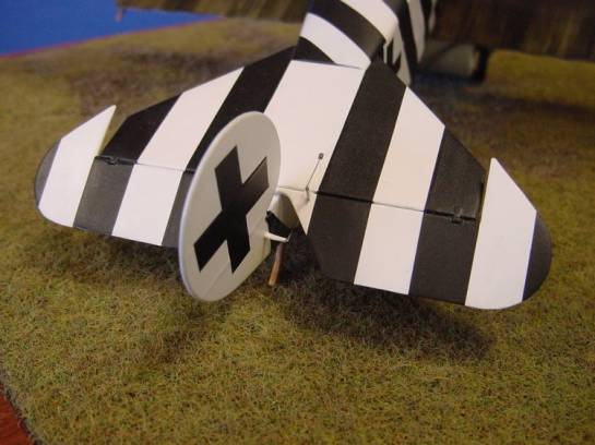
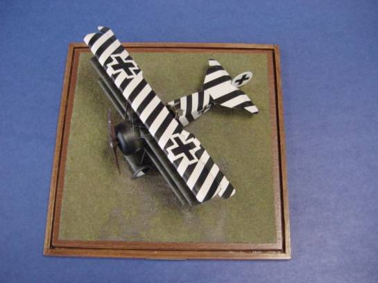
All of Kirschstein's aircraft were painted with stripes similar to those depicted on this model. It was believed that the disruptive nature of the different angles would throw off the aim of any pilot who found himself on the tail of this aircraft. It has been said that this aircraft only received hits in the port wings, so perhaps it worked!
The following is a list of modifications I made to the Revell 1/28 Fokker Dr.I, more or less in the order in which I did them. Every single part of this kit was modified in some way.
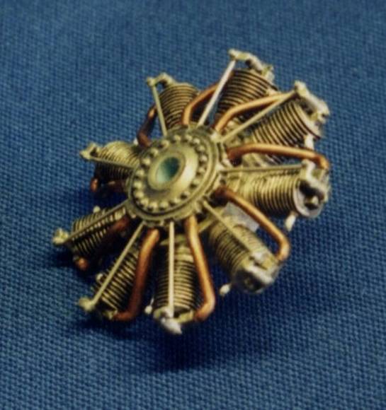
Oberursel URII Rotary Engine
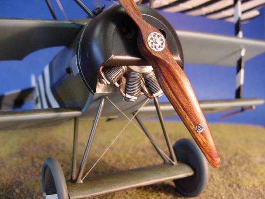
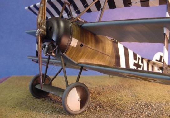
The push rods were moulded onto the cylinder heads so they had to be removed and the slots on the cylinders carefully re-scribed. New rods were added from steel rod and plastic card, and spark plug wires added from nylon thread. All sink marks were filled as well. The Axial propeller is hand-carved by Martin Digmayer of the Czech Republic and the boss is photo-etched brass with nuts added from little bits of plastic rod. I made the Axial logos by hand on white decal film using a Micron Pigma technical pen, which required a steady hand and a lot of failed attempts to get two that I liked.
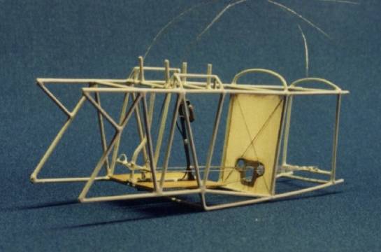
Cockpit and Fuselage
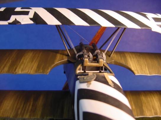
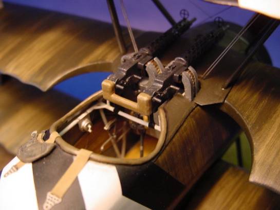
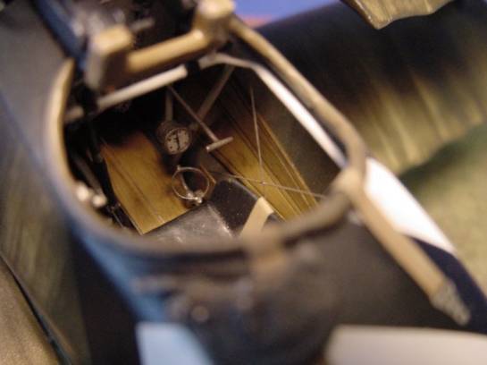
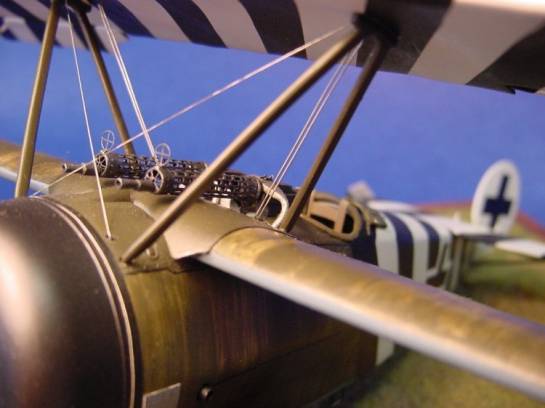
To begin, all moulded-on cockpit detail was removed including the cockpit floor locators. The plastic was then thinned on upper cowl panels to simulate the thin sheet aluminum. All internal details were then scratch built as follows: the framework from plastic rod, the plywood skinning and ammunition containers and chutes from plastic card, all instruments (there are only three) and controls from scratch, and cables and bracing wires from nylon thread. The only exception was the mixture control, which was photo-etched brass from Tom's Model Works with a handle made from building up layers of white glue. The instrument faces were made by reducing photos of actual German flight instruments with a photocopier and include a tachometer, altimeter and fuel gauge. The compass stand was made from scrap bits of brass and was installed without the compass. The machine guns were made form photo etched brass from the Tom's set and some scratch details. The ammo belts also came from the Tom's set, but I rounded the bullets with several careful applications of cyano glue. This gives a shiny, polished brass look which does not require painting. The cockpit coming was smoothed out with filler putty after the fuselage had gone together.
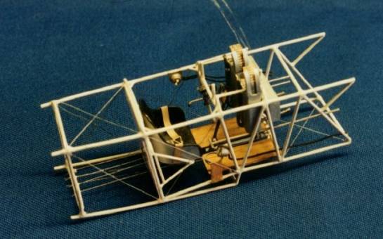
A hole for the tail skid had to be cut into the rear of the fuselage and a new skid built from plastic card. The locator holes for the foot step and hand holds had to filled as the kit parts are very over-scale and had to be replaced with fine lead wire. The holes for the fuel gauge (which was located just aft of the engine cowling between the guns) and aileron control cables had to be drilled out as well. Magneto access panels made from plastic card were added to both sides of the fuselage aft of the engine cowling. This was a Jasta 6 field modification and not generally seen on other Dr.Is. Air intake pipes were also added from brass tube.
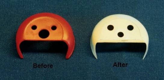
The engine cowling that is supplied with the kit was inaccurate (i.e. the front plate should slope down towards the engine at the base, and the propeller shaft hole was too large) and was the most difficult part of the kit to correct. This was accomplished by adding an extension to the front plate from thin plastic card followed by filling the join with super glue and sanding smooth. The hole for the propeller shaft was made smaller by filling it with a ring cut from thin plastic card and then filling the join with cyano glue and sanding flush. All edges were thinned to represent thin sheet metal, a manufacturer's plate was added to the starboard side of the cowling from plastic card, and the cowling retaining cable was added from fine copper wire.
Horizontal Stabilizer
The shape of this item was inaccurate as well. The width at the trailing edge was a little too large resulting in to great a surface area and an incorrect angle for the leading edges. This excess plastic had to be trimmed off and the width of the elevators had to be reduced in size as well. All surface detail was sanded off and replacement rib tapes made with an undercoat of thick enamel paint. This gives a very nice scale effect after the final finish is applied to the model. Scratch-built hinges made from brass sheet and plastic rod were added to the horizontal stabilizer and fuselage for the elevator and rudder respectively. The fit of the horizontal stabilizer to the fuselage was also poor requiring a lot of filing and sanding to get it to sit right. Incidentally, the width of the horns where the tailplane meets the fuselage had to be increased using cyano glue. I did this by first putting a piece of masking tape under the horn to provide support for the glue and then gradually built up layers of glue past the width required for a proper fit. After carefully removing the tape I even more carefully sanded the glue flush and to size. I also used this technique to build up a portion of the cowling that had not completely formed in the injection process. With some care it is possible to sand the glue to a razor sharp edge, but you may have to try it more than once as the glue can break off during the process!
Wings
The scallops between ribs were over-scale (which is true of most models of WW I aircraft) so all rib detail was sanded off and replaced with thin strips of tape. I used pinstripe-detailing tape for large-scale RC model cars. These ribs were blended into the wings by applying a heavy coat of thick primer paint and then wiping off most of the paint before it dried with a finger run between ribs. After repeating this process several times with light sanding between coats, a very realistic scale representation of rib scallop results, although it is difficult to see in these photos. I picked up this technique from John Alcorn's excellent book Scratch Built!, which is published by Schiffer Publishing.
The ailerons provided in the kit include one that was early style and one that was late style with a larger surface area. This modification to the aircraft was seen on some early Dr.Is and was probably intended to help overcome the engine torque. However, I needed two late style ailerons so after removing both ailerons from the upper wing, I had to increase the surface area of the early one by cutting off the inboard end at the second rib and replaced it with one made from plastic card.
Final Details and Painting
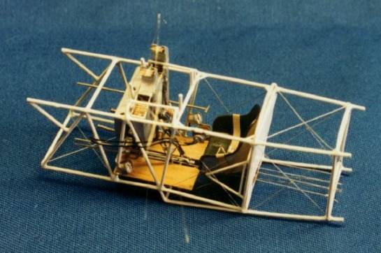
The landing gear axle wing was actually made of plywood and should have a smooth finish so all of the rib detail was sanded off. The detail on the wing struts and wheels was quite heavy and had to be sanded down somewhat. All control horns were made from plastic card, as were the two wing tip skids, and all control cables and bracing wires were added from nylon thread.
The seat belts are photo-etched brass with a little detail added to the lap belts. The pilot's cap lying on the fuselage was scaled down from an actual WW I German pilots' cap that I own, and was made from paper and white glue. This little accessory, while adding character to the model, became a necessity after I jammed a pair of needle nose pliers into the freshly painted model while trying to reposition one of the aileron control cables. The thought of filling and sanding this gouge and redoing the masking for the stripes (for the third time I might add, but that is another story) was too much to bear.
The streaky olive finish on the fuselage and wings was the standard Fokker factory finish in 1917 and early 1918. This was applied by hand using Model Master acrylics in much the same way it was done in the factory on the original aircraft by dipping a coarse, flat brush in olive paint and dragging it over a linen base coat until the paint ran out. This process was then repeated by section until the wings and fuselage were covered. The paint was stoked on very gently and I usually had to go over each section a couple of times. It took a lot of trial and error on a spare Dr.I kit to get an effect that I liked before I attempted painting the model! The national markings were all masked and airbrushed along with the black and white stripes, which was almost as tedious a process as replacing the wing ribs. All colours were matched as closely as possible to paint chips provided in Windsock Vol. 2, No. 2, including the under-surface blue-green.
All in all this was a rewarding project during which I think I learned something more of this hobby. It took me about a year to complete, although I have no idea how many hours in total I spent at the hobby bench. A few too many of them were spent cursing the model, my abilities, and lack of good fortune though!
References
- The Fokker Triplane by Alex Imrie, Arms and Armour Press, 1992.
- Fokker Dr.I, Windsock Datafile Special, Albatros Productions Ltd., 1991.Z
- von Richthofen's Flying Circus: Colors and Markings of Jagdgeschwader Nr I. by Greg VanWyngarden, Albatros Productions Ltd. 1994
- Windsock International, Vol.8, No.4, July/August, 1992. Pp. 15-19.
- Windsock International, Vol.2, No.2, March/April, 1985, p.21: Paint chips from Fokker Dr. I fabric samples.
- WWI Aero, No.128, May 1990, pp. 70-71
- WWI Aero, No.123, February 1989, pp. 75-77
- WWI Aero, No.122, December1988, pp. 69-73
We here at Large Scale Planes would like to thank Steve Bamford at ARC for the use of this article.
© Martin Gastel
This article was published on Wednesday, July 20 2011; Last modified on Saturday, May 14 2016