
Swallow 1/32 Mitsubishi A6M2 Zero
By Randy Lutz
Swallow 1/32 Mitsubishi A6M2 Zero
In the markings of Major Sigeru Itaya of the Carrier Akagi during the Hawaiian Operation
The Model
For those of you not familiar with the Swallow label, it is a re-release of the old Tomy moulds. I am not sure when this kit was originally released, but judging from the provisions for motorization, I surmise it was probably in the late '60s or early '70s.
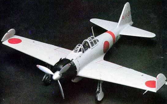
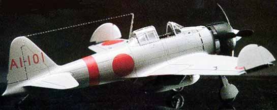
The model is pressed in a light grey styrene with minimal flash. All surface detailing is of the recessed variety, albeit a little heavy for my liking but superior to raised panel lines. The clear parts are relatively thin with fine scribing indicating the canopy framing. Perhaps the most critical aspect of a Zero is the cowling with its complex curves, and this is an area which is highly accurate once completed. All the kit parts are packaged in a plastic bag with the clear parts and decals each packaged in their own plastic within the main bag. This is something I wish all manufacturers would do as it prevents scratched canopies and decals are unaffected by moisture. The decal sheet is of excellent quality, although my sample was slightly off register, and has markings for 4 aircraft. Three are overall grey. Two of which are from the Tainan Air Corps, with fin numbers V-141 and V-107. The other grey machine is A1-101 from the carrier "Akagi". The sole green machine represented is from the Kounoike Air Corps. I elected to build A1-101 which participated in the Pearl Harbour attack.
The first step involved assembling the engine and cowling. The engine has the rear bank of cylinders moulded on the firewall, and the front bank has no back to them. All cylinders were painted with Humbrol Gunmetal, with a liberal wash of black paint applied to highlight the details. The pushrod and ignition harness were spray painted silver and the crankcase was brush painted gloss grey, and then fastened to the cylinders. The engine assembly was then trial fitted into the cowling components. This proved to be the only area of the kit where I encountered any construction or fit problems. The cowling is comprised of four pieces, these being the nose ring, left and right halves and the top. All of these are designed to encase the engine and firewall. But, it seemed that no matter how much shaving was performed on the engine assembly, it was too big for the cowling to properly encase it. After much fitting a liberal application of Zap-A-Gap filled all resultant seams. All the cowl flaps were cut apart, gently opened and the trailing edges were thinned to a scale thickness. A bead of Zap-A-Gap on the inside secured the flaps in the open position. Once sanded, the cowl was painted with Tamiya TS-6 Flat Black spray lacquer and set aside for installation later. The oil cooler intake is incorrectly moulded to the cowling. This was removed with a razor saw and fastened to the housing on the bottom wing. Afterwards, it was blended in with Zap-A-Gap.
The instrument panel is nicely moulded, however the detail of the dials have been omitted from the faces. This necessitated drilling out the instruments and installing Waldron Japanese instruments. A few instruments were also installed in the side consoles. Not a big job, and well worth the final result. Prior to painting the cockpit components metallic blue,(I know they should be an olive green colour, but I used the reference I had at the time) the pilot's seat back was drilled out using the kit supplied engraving as a guide. Smaller cockpit details were highlighted with gunmetal and various shades of white, yellow and red. A set of Model Technologies photo-etched seatbelts and buckles were added to the seat. The gun charging levers were fabricated from small scraps of metal, painted yellow and glued to the machine guns in the cockpit. As a final touch, a Model Technologies photo-etched ring sight was glued to the gunsight. This entire assembly was then trapped between the two fuselage halves.
Prior to assembling the wings, the wing tips were cut away along the hinge line, and the landing flaps removed. All the wing ribbing was formed from sheet styrene and installed on the flaps and the under surface of the upper wing following the rivet pattern moulded in. A main spar was also super glued in the wing to block off the opening that remained from the removal of the flaps. Both the wing spar and all ribs had the appropriate weight reduction holes drilled out. Ribs were fabricated from sheet styrene, drilled out for appearance and installed in the ends of the wings and wing tips. Afterwards, the wings were assembled and fastened to the fuselage.
The wing root joints do not require any filling, however the tailplanes do require a fair amount of putty and sanding. All seams on the airframe were smoothed over and any rivet detail lost was replaced using a small push pin to form the indentations. Prior to installing the canopy, The decking behind the pilot's seat was painted metallic blue and the DF loop was installed. All canopy framing was masked off using thin strips of masking tape, and then the front windscreen and the rear canopy were glued in place. White glue was used to blend in the clear pieces to The fuselage.
All openings in the model were stuffed with paper towel or taped over and then the model was painted using a Paasche V double action airbrush and Tamiya XF-20 light grey acrylic paint. Afterwards, the wheel well openings, inside surfaces of the flaps and the exposed areas which resulted from the removal of the wing tips were brush painted metallic blue. As a point of interest, do not attempt to assemble this model with the landing gear in the retracted position. There is no conceivable way the doors will fit the wheel openings. They look as though they will fit, but not a chance! I have learned this the hard way as I am in the process of converting another Swallow Zero to represent an A6M2-N Rufe. This leads me to The landing gear assembly. Humbrol gunmetal was brush painted on all parts that would have been metal on the original and then the oleos were highlighted with Testors silver. Small holes were drilled in the landing gear doors where they are designed to fasten to the undercarriage and .025 wire passed through to represent the brake lines. The main landing gear and tailwheel were installed in addition to other small items such as the antenna, pitot tube, and aileron mass balances.
As I had elected to display this plane with the landing gear and flaps dropped, it seemed reasonable that the pilot's boarding step should be extended. This was fashioned from scrap plastic and inserted into a hole which I had previously made. The hand hold just in front of the Hinomaru, and the Landing Gear position indicators were made from small pieces of wire and super-glued in place. Next the cowling was glued to the front of The fuselage. If you elect to open the cowl flaps, it will be necessary to shim the mounting boss on the fuselage to ensure proper alignment as it would appear that in stock form the cowl flaps rest on the fuselage, and the engine assembly offers no support whatsoever. The cowl mounted machine guns were replaced with gun barrels from an old Hasegawa Mustang, drilled out, trimmed to proper length and installed in the upper decking.
After this was completed, the entire model was airbrushed with a few coats of Future acrylic floor wax to obtain a glossy surface for the decals. All decals were trimmed close to the colour edge and were applied using Solvaset. As stated earlier, the decals were slightly off register, and it was most apparent around the stencils and wing walk areas. I added the small individual aircraft numbers to the bottom of the engine cowl, drop tank and under carriage doors by means of Letraset dry transfers. These markings are not included with the kit decals, but judging from photographs of Zeros taken during the Hawaiian Operation they should be added. I believe The kit instructions are quite accurate in not indicating the yellow tail stripes commonly seen on Zeros operating from the "Akagi". I have not been able to discern tail stripes on any photographs of this particular machine.
The exhaust pipes were drilled out and painted a dark earth colour, after which they were glued to the bottom cowl flaps. The bottom cowl flaps are stationary and should not be shown in the open position.
Next the model was given a few coats of Testors Dullcoat to reduce the sheen and blend in the decals. All control surfaces and various inlets and outlets were defined using black India ink and a Koh-I-Noor technical pen.
The propeller and spinner were spray painted with Testors Metallic Silver, and then the back side of the blades were brush painted flat black. Afterwards, Crimson Red decal material was cut into small strips and applied to The propeller tips. In my opinion, this produces a much neater appearance than paint. The propeller assembly was then glued to the engine crankcase. As a final touch, the navigation lights were painted with Humbrol gloss dark red and dark green. A stretched sprue antenna wire was added and the insulators were made from white glue which was painted gloss white when dry.
The completed model captures the lines and gracefulness of the Zero very accurately. It is a kit which went together with a minimum of problems and is a must for anyone wishing to complement the Revell and Hasegawa A6M5 kits.
References
- Aircam Aviation Series No. 16 (Vol. 1) - Mitsubishi A6M1/2/-2N Zero-Sen in Imperial Japanese Naval Air Service. Osprey Publications Limited, England.
- Zero in Action No. 59 Squadron/Signal Publications, Texas
- A6M Zero No. 323 Model Art Company, Tokyo
© Randy Lutz
This article was published on Wednesday, July 20 2011; Last modified on Saturday, May 14 2016