
BMW 109-003 Engine
Photos By Max Otten
Photos were taken at the South African Military History Museum, Johannesburg (South Africa) in 2015.
The BMW 109-003 is jet engine (powering for example the Heinkel 162). The one in the museum differs in a number of details from other engines like the one from the Heinkel 162 in Paris (there are a lot of detailed photos from its restoration). One notable difference is that the Paris engine has its many pipes and lines coloured in standard German colors (e.g. yellow for electrical wiring, red for oil, blue for hydraulics?) while the engine in the museum lacks most of these (except for the electrical wiring which has turned a rather drab yellow by now).
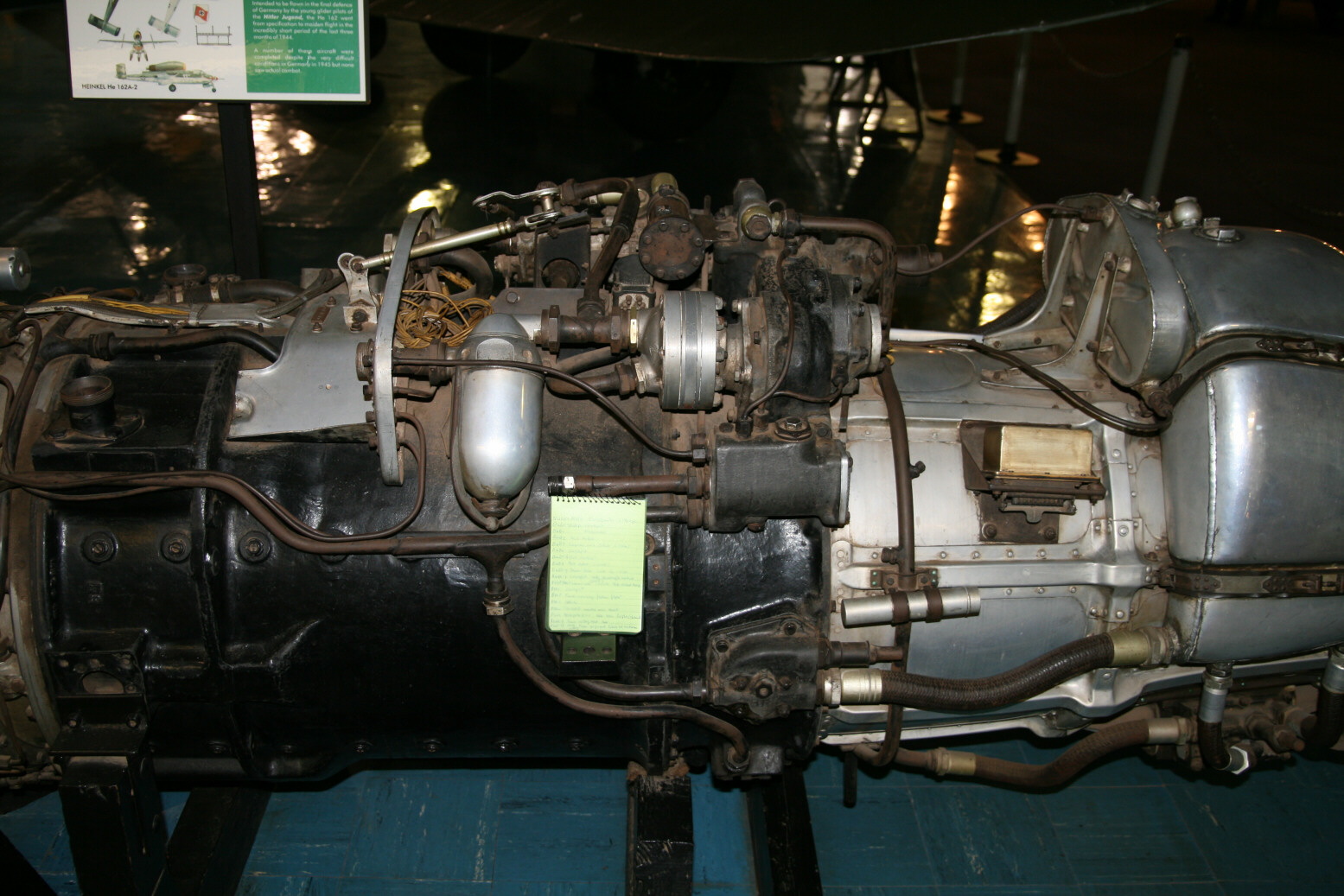
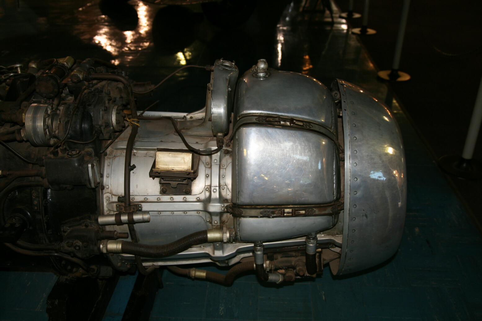
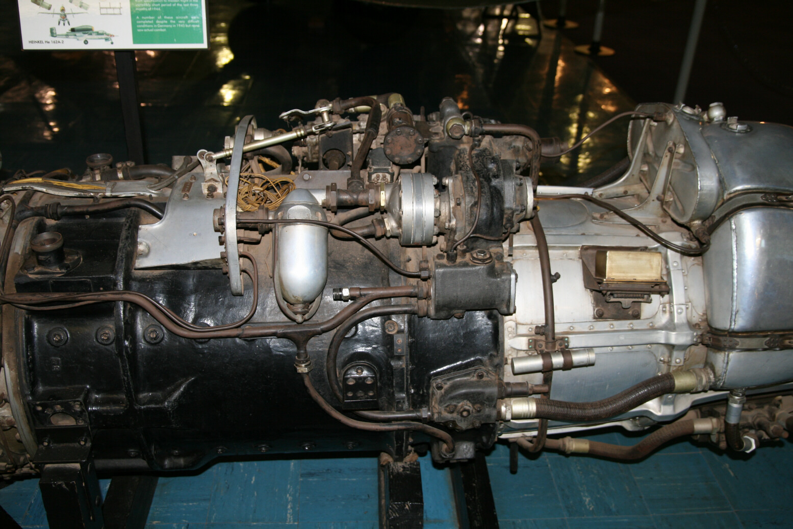
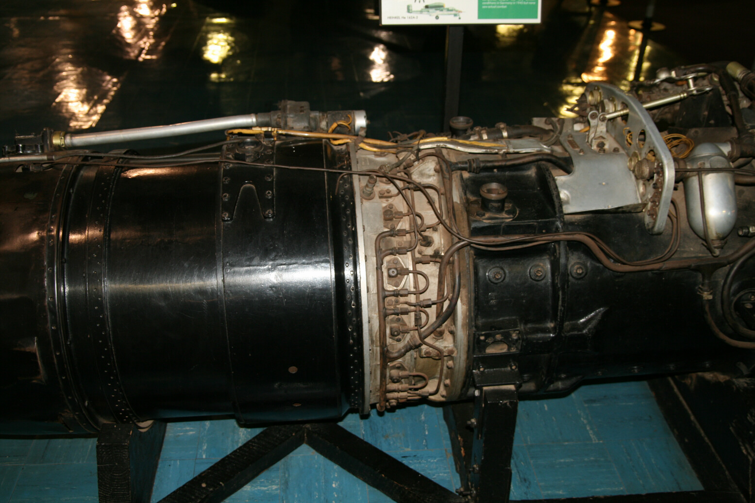
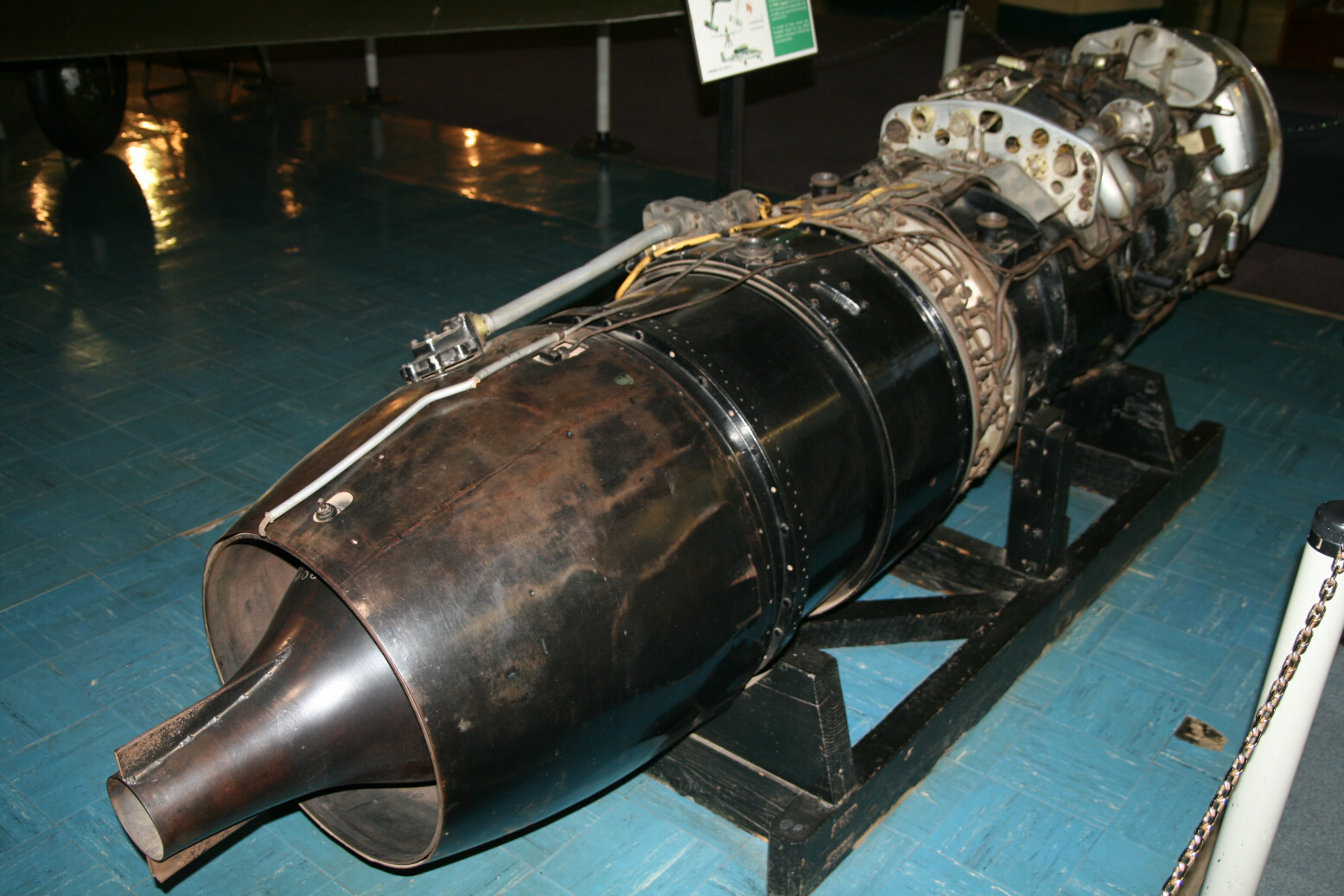
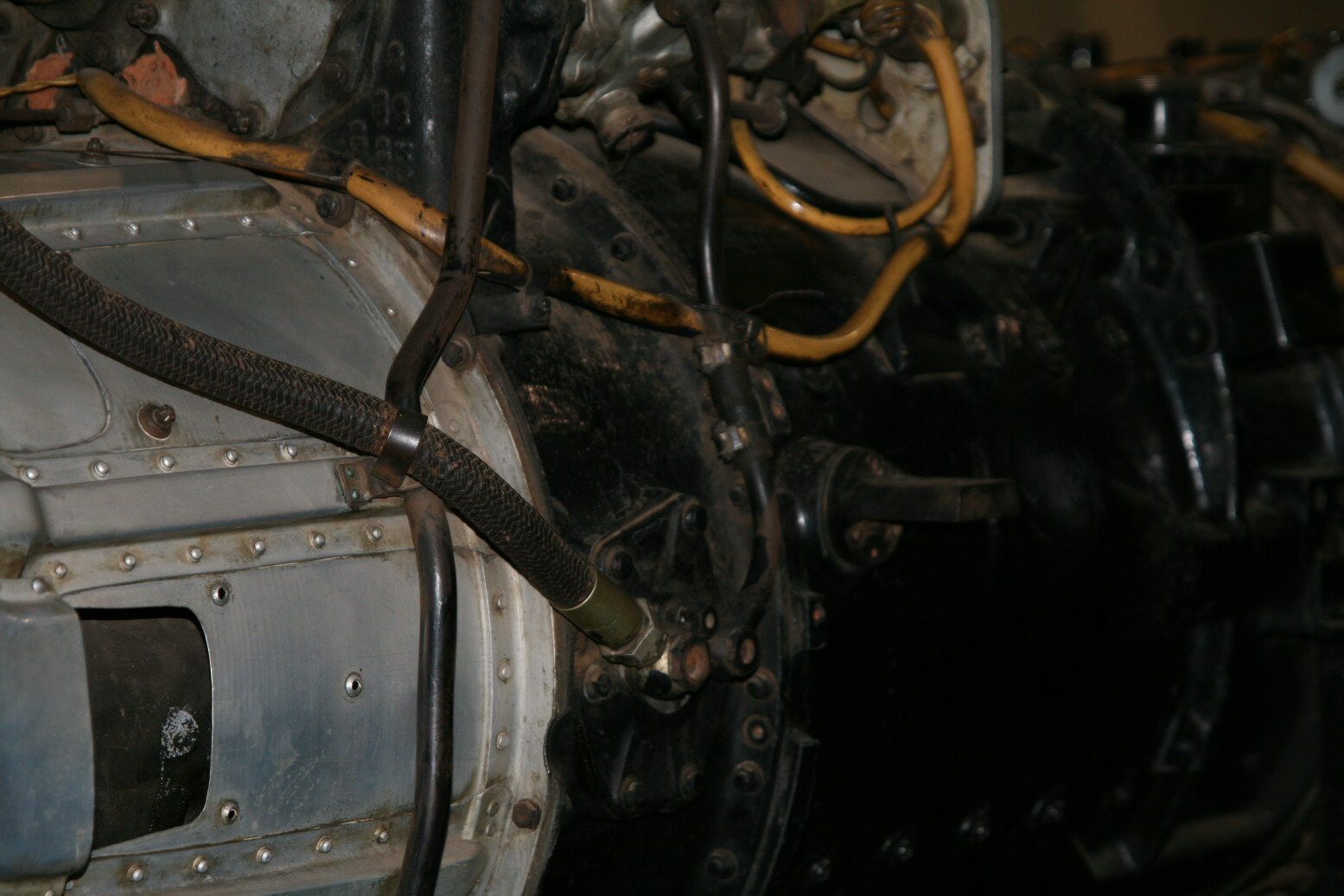
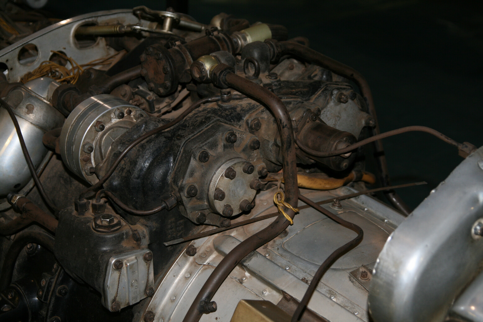
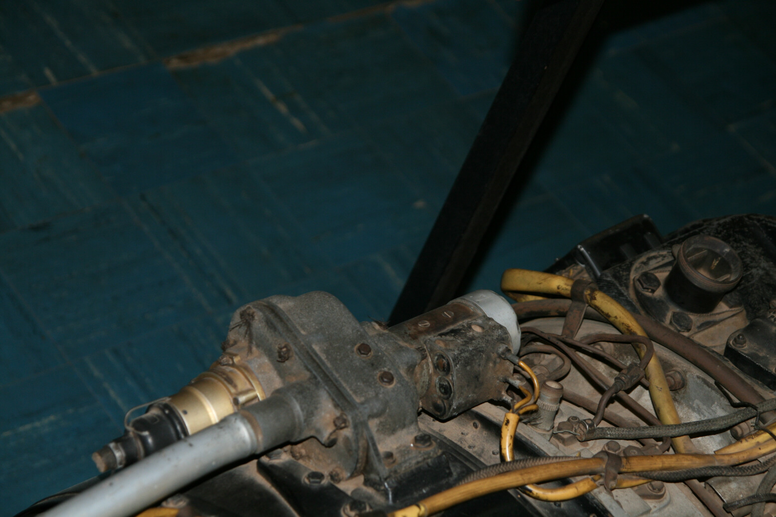
Photo 1 (above) starts off with a partial view of the starboard side of the engine. The white rectangle in the mid-foreground is my notepad that I put there as a scale indicator (width 10.2, height 15 centimetres). I put it there as I frequently have problems in establishing dimensions in reference photos. Photos 2 through 4 (above) walk back along the engine, while 5 (above) shows the back at a different angle. First the major units of the engine (from right to left):
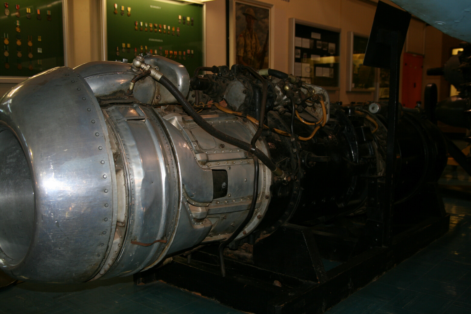
- The inlet cone.
- This is followed by what is described as the ‘front housing’ (aluminium).
- A black ring, about 15 centimetres wide, on top of which are all kinds of accessory units like the oil and hydraulics pumps. This ring contains the gears to drive the accessories.
- A long black cylinder which is the compressor. This contains a large number of vanes that compress the incoming air before it goes into the combustion chamber.
- Which is the next (steel) unit with all the fuel lines and injection points plus the black cylinder (about three times as wide as the bare steel unit) behind it.
- And then finally the propulsion nozzle, the black part at the back that starts out as a cylinder but then tapers down. Inside it is the nozzle.
Now for the details, again going from right to left:
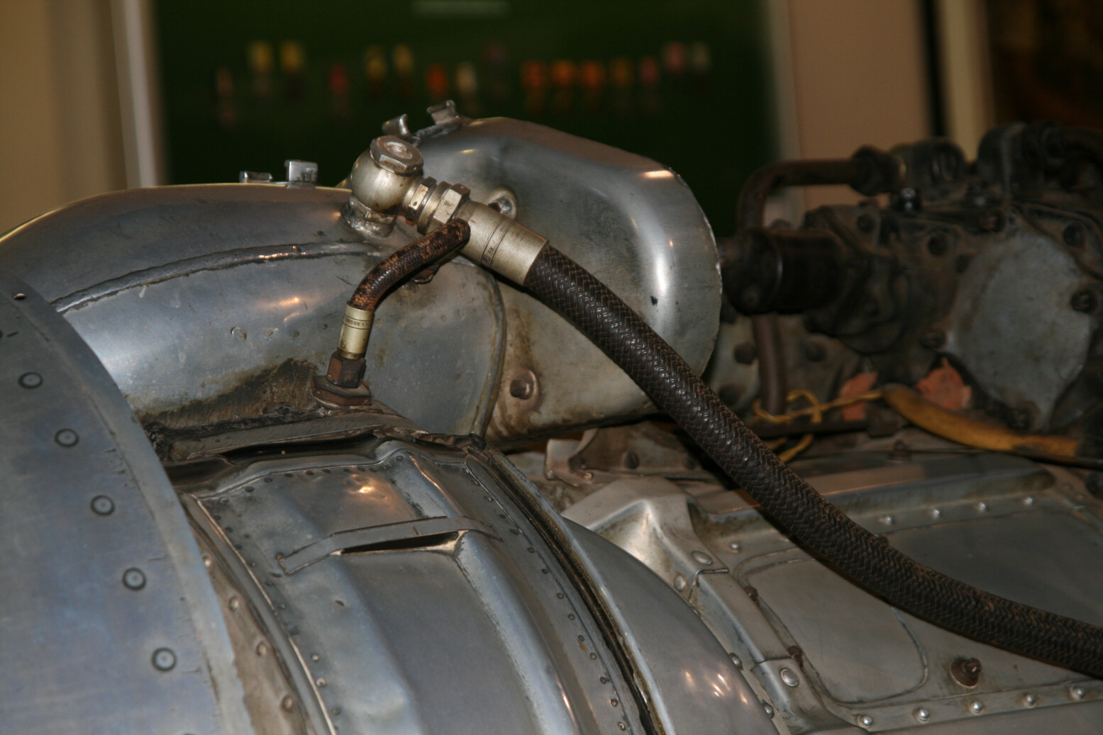
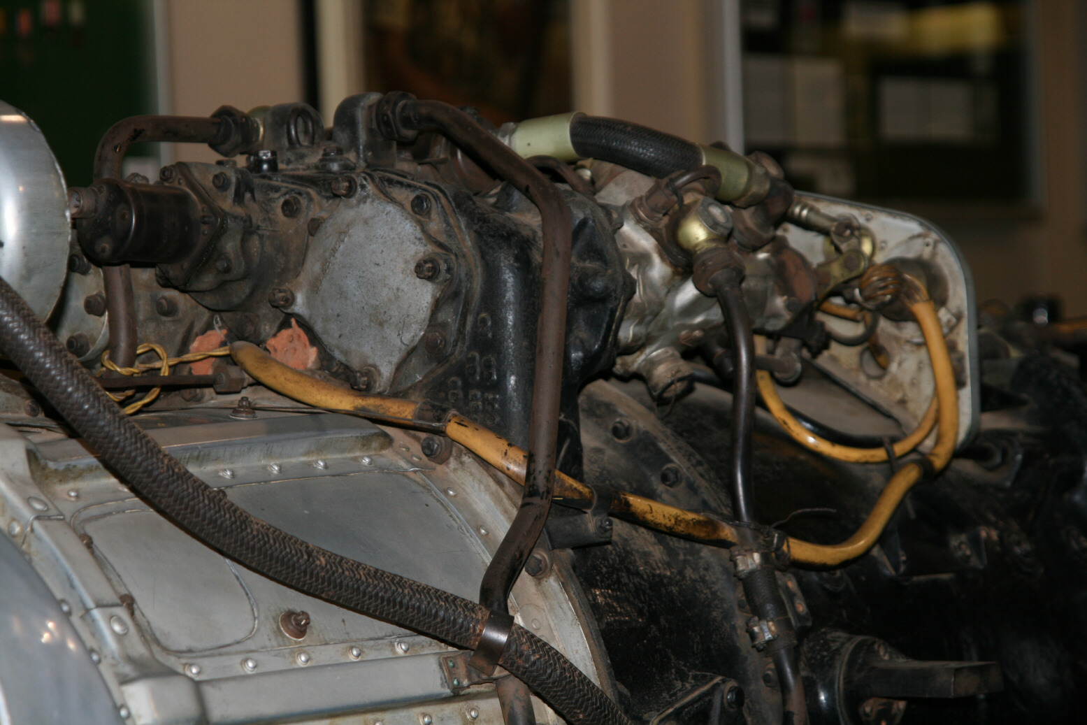
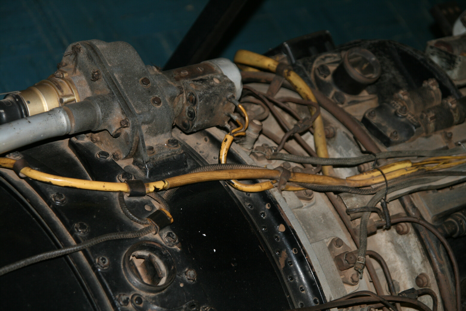
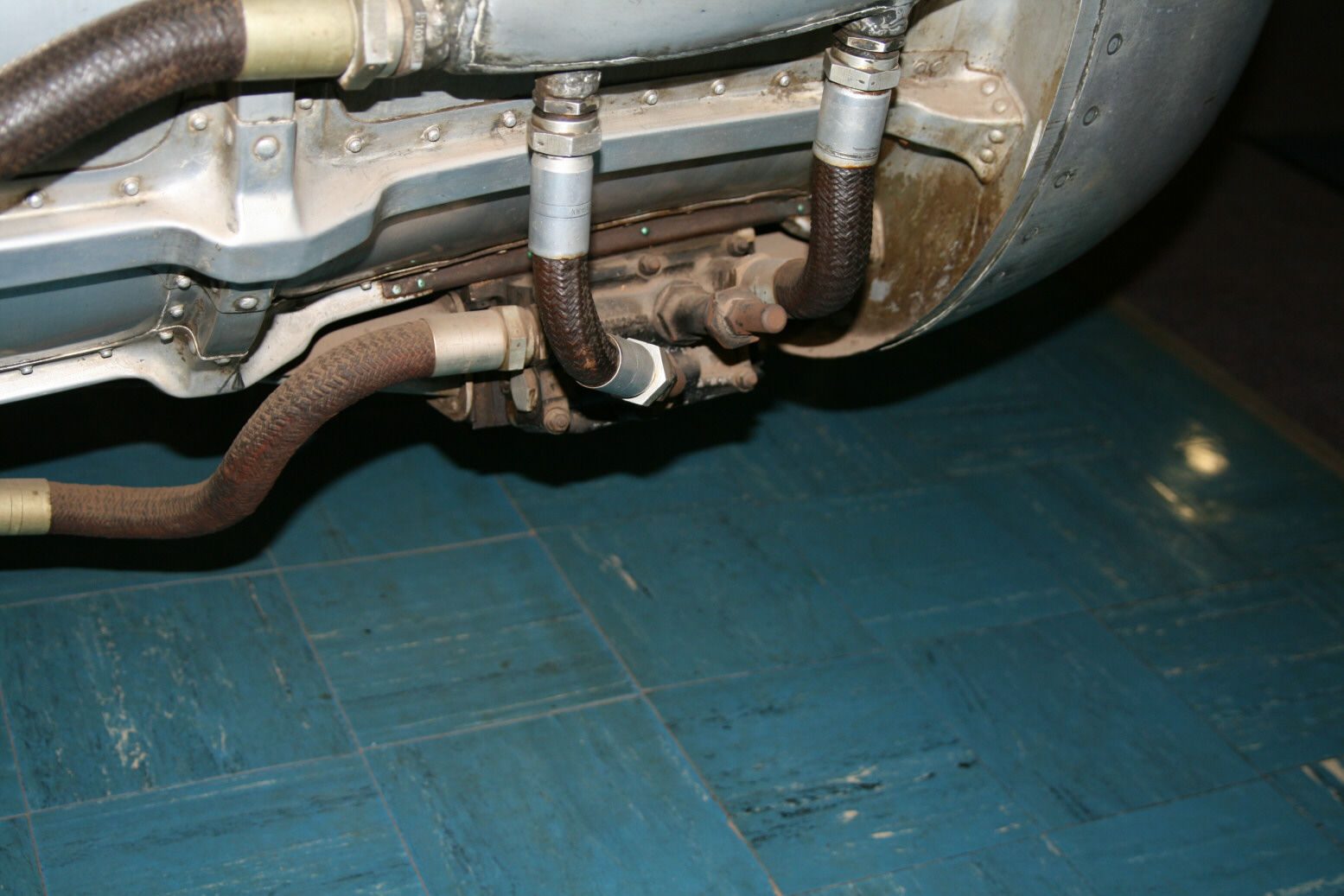
- The oil tank is the aluminium unit strapped down just behind the inlet cone. Underneath it is the oil cooler. The pipes coming from the oil tank are one point where this engine differs as the Paris engine has the pipe going down at the back plugged up. I don’t know how the oil flows through all these pipes, all I know is that the oil pump is the black ‘horse shoe’-shaped unit towards the back, connected to the oil tank by the horizontal pipe. There is a return pipe to the top of the oil tank coming from the other side.
- Just to the left of the oil tank at the top is what I presume to be the fuel tank for the Riedel start engine (that itself is located in the nose cone inside the inlet). On other jet engines this is a cylinder, but here it appears to be a flat part.
- As already said, the oil pump is to the left, connected by the horizontal pipe. From there a pipe in the shape of a half circle goes up and plugs into the oil filter, somewhat above the oil pump.
- Above the oil pump/filter combination is the fuel pump, a complex unit in itself. The ‘bottle’ to the left and connected to the fuel pump is the fuel filter. Mostly on the other side of the top of the engine (so behind/above in these views) is the fuel regular.
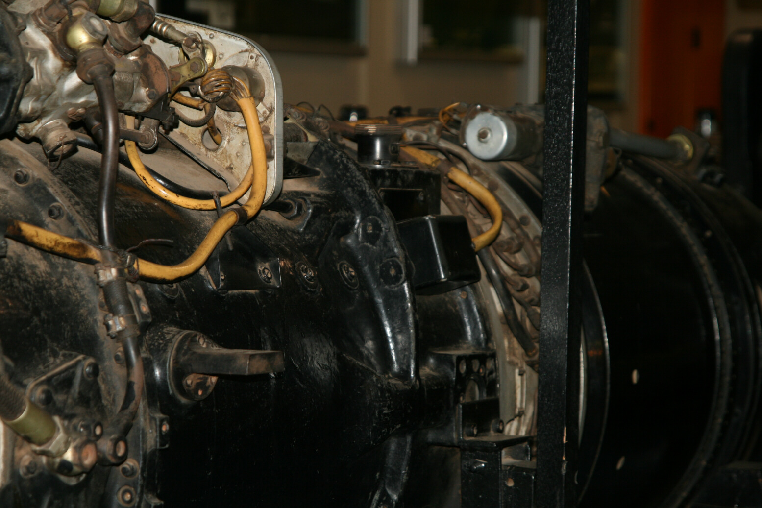
- Going further back there is a plate with lots of holes and connectors.
- On the combustion chamber you see the intricate system of fuel lines.
- The large bar on the top of the combustion chamber to the propulsion nozzle is used to adjust the position of the nozzle itself. It the nozzle is moved further backward, the pressure is increased so the jet action becomes stronger. Unfortunately this would cause this engine to overheat so its use was severely restricted (and thus the maximum speed of the Heinkel 162 was much less than what it was supposed to be). The nozzle adjustment bar seems to be missing on the Paris engine.
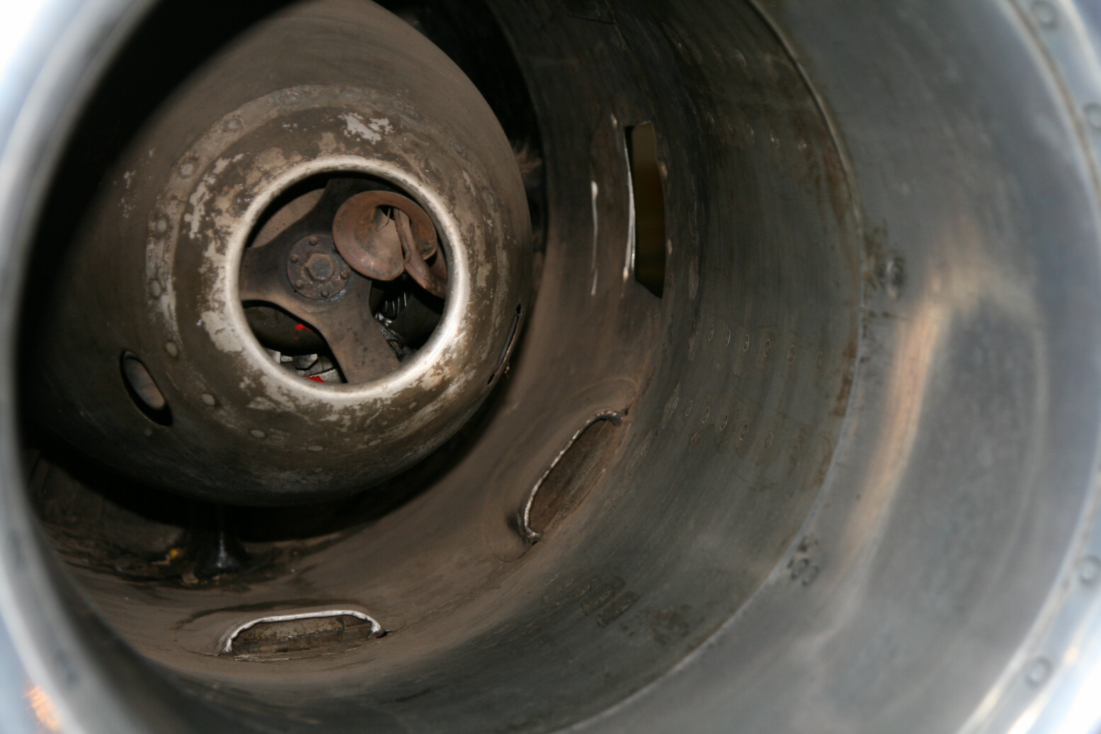
Moving to the other side of the engine (which isn’t as accessible), we get photo 6 (above). There is a unit just behind the inlet cone (like a ring with two outlets). I presume this is part of the oil cooler system. Inside the inlet cone (photo 7, above) there are holes/inlets to draw air into this unit.
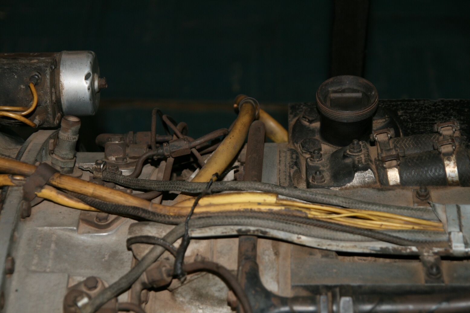
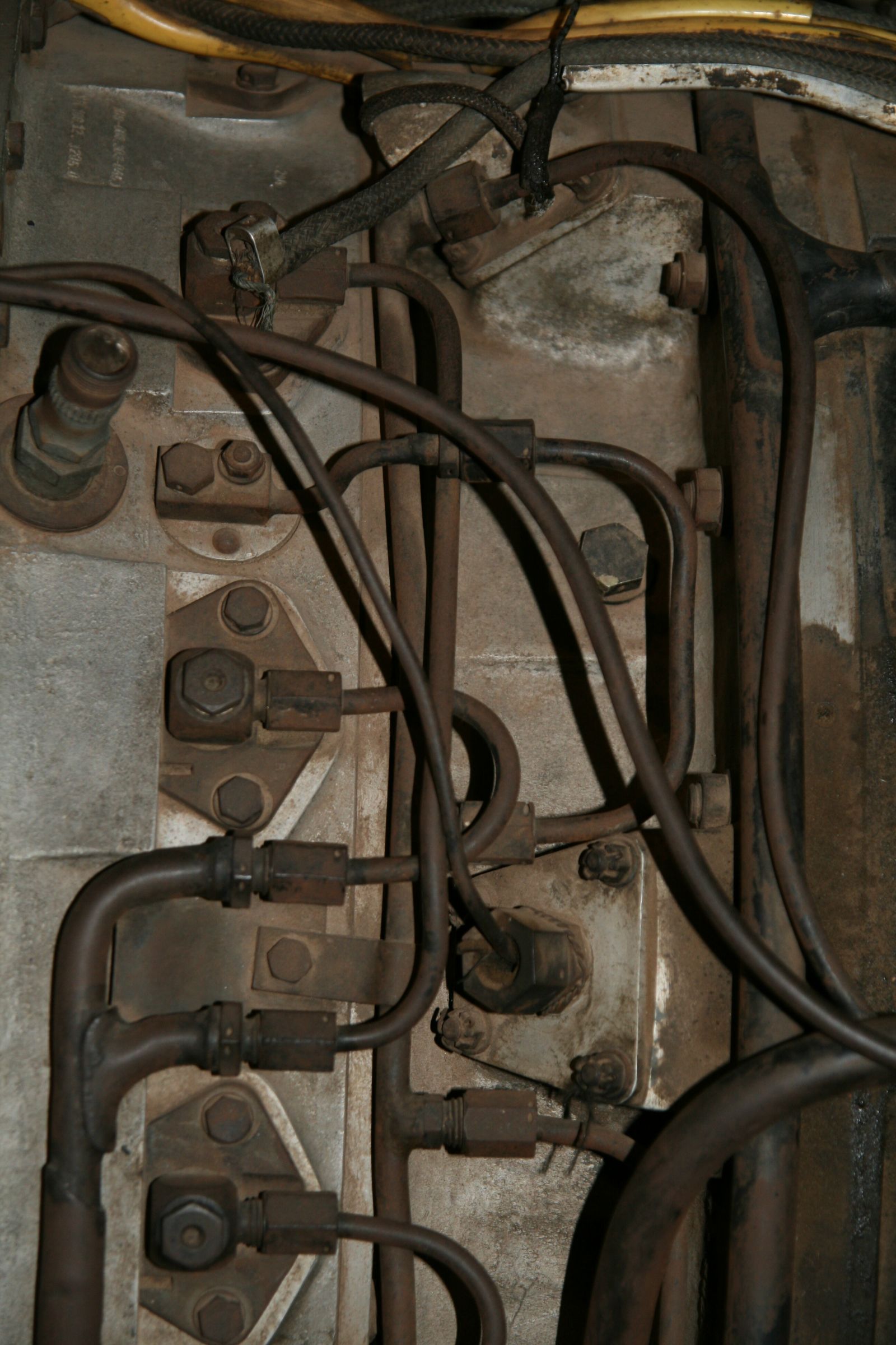
Photos 8 through 11 (above) show details on this side of the engine. Photo 8 has the top of the oil tank and the pipe coming into its top. Photo 9 follows this pipe further down. Photo 10 is actually in between 8 and 9 (see can still see the pipe) and in the center you can see the location where the hydraulics pump is on the Paris engine but here is just a cover plate (the lighter grey square)? Further right, behind it is the fuel regulator which is the very complex unit in bare metal. The yellow cable is electrical wiring. It is connected to the big connector on the plate. I think this where the wiring coming up from the fuselage plugs in (none of the reference photos ever show a cable connected there so I can’t be sure). Photo 11 moves further back along the engine. In the center is an electrical connection box. The bare grey circle is the tip of the nozzle adjustment bar.
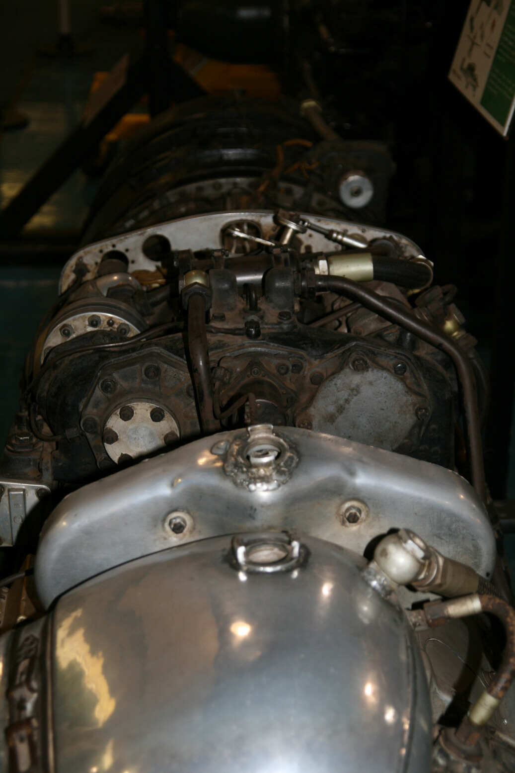
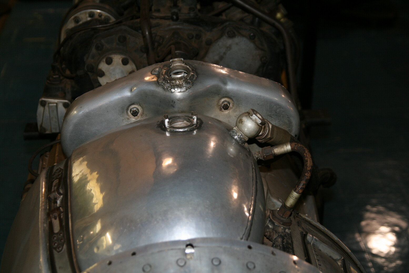
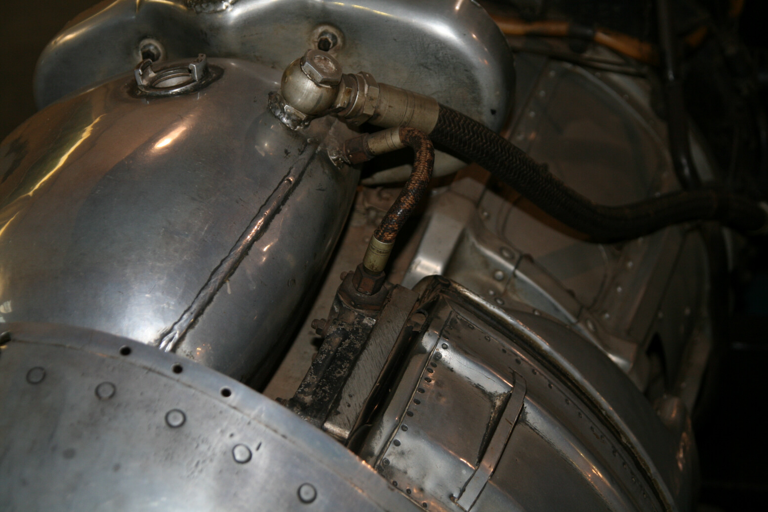
The next set of photos shows things more from the top/front. Photo 12 (above) is a bit of an overview, with the oil tank up front (filler plug in the center), then the Riedel engine tank, the ‘ridge’ with the auxiliaries and the plate with the connections. Photo 13 (above) shows the oil and Riedel-engine tank in more detail (the plug of the Riedel-engine tank is missing), while photo 14 (above) is at a slight angle and shows the pipes going into the oil tank. Photo 15 (above) shows the ridge with the accessories from the front/side. Photos 16 and 17 (above) also show the accessories, now from the other front/side. I have no idea what the two units are (one octagonal, the other the black cylinder sticking out towards the front).
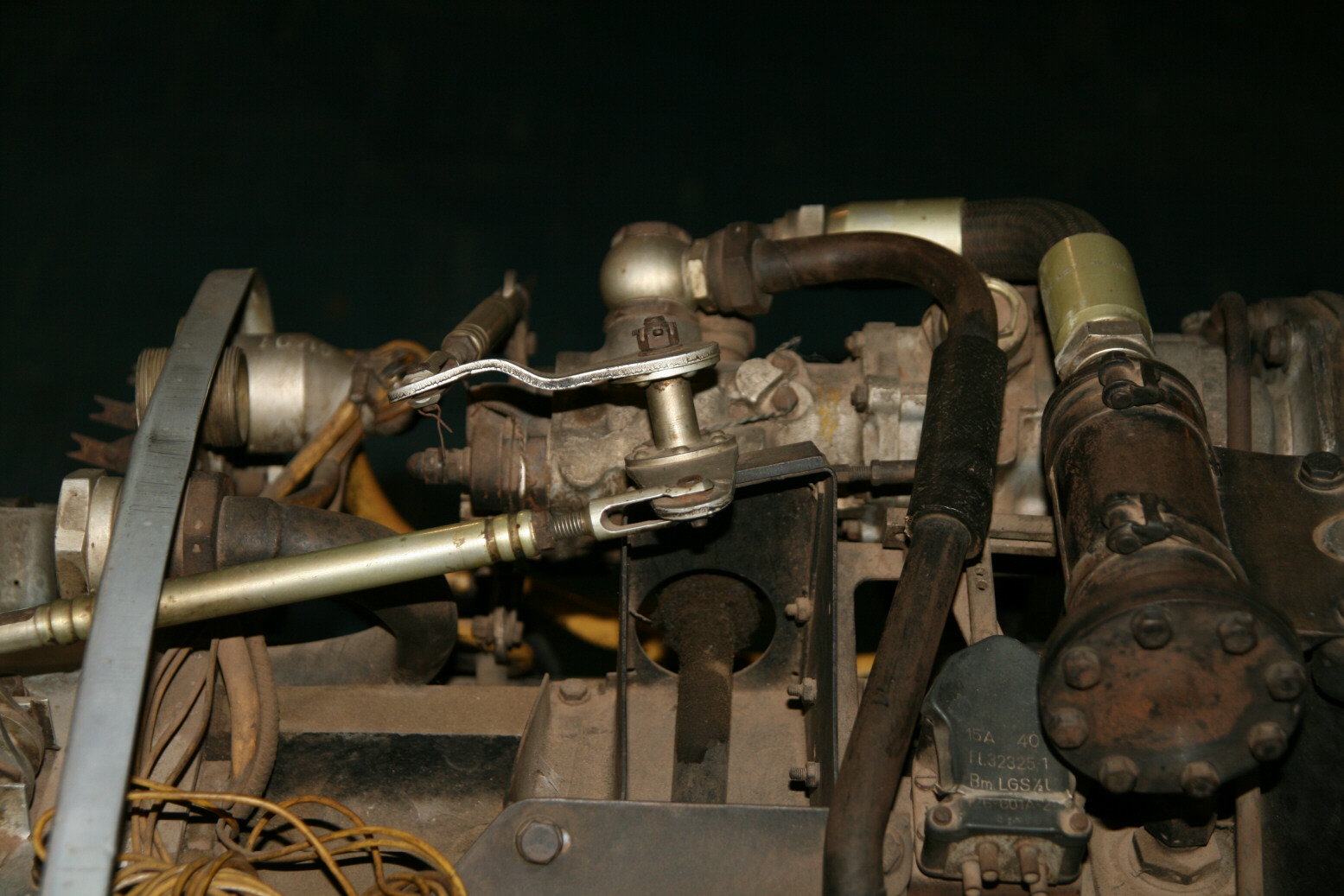
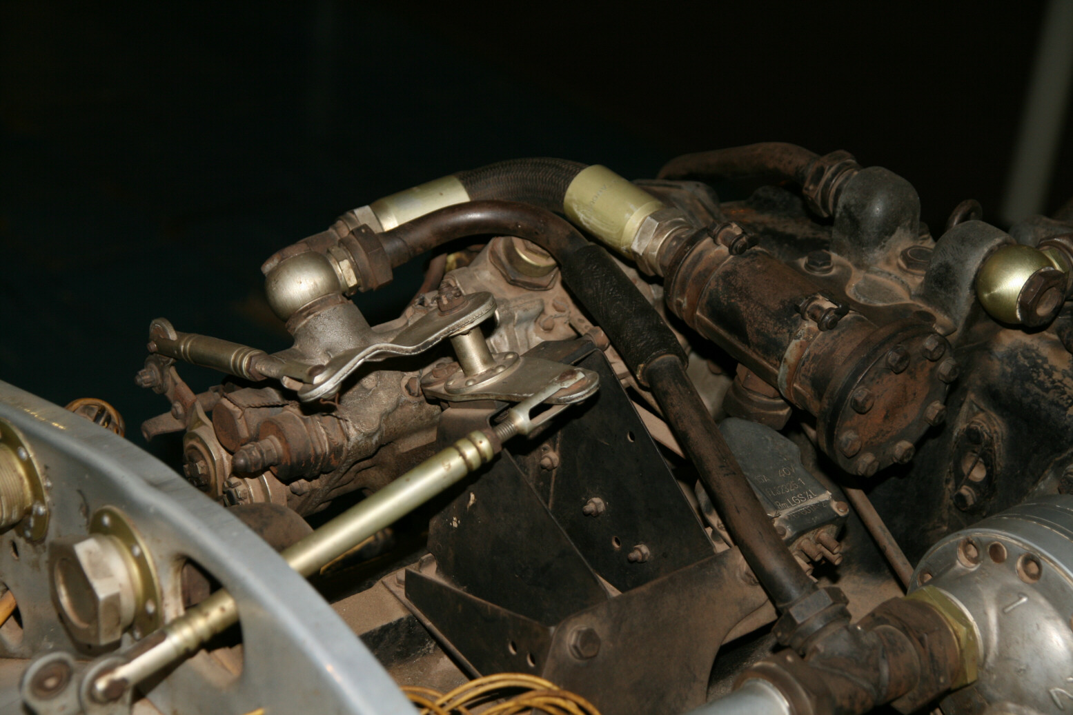
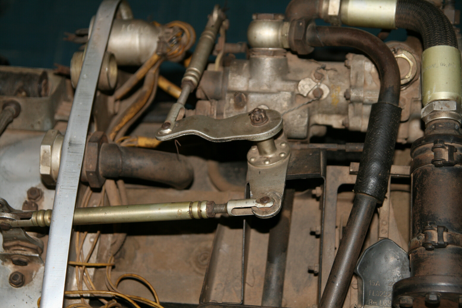
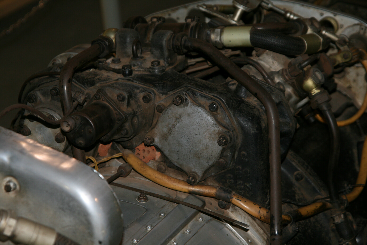
Photos 18 through 21 (above) show the fuel controls. The ‘silver’ rods must be the throttle controls (which also explains the odd shape of the unit with the plates – on the Paris engine this odd-shaped unit seems to serve no purpose but here it clearly is the unit on which the throttle control rods are articulating). Photo 20 shows the fuel pump from the top.
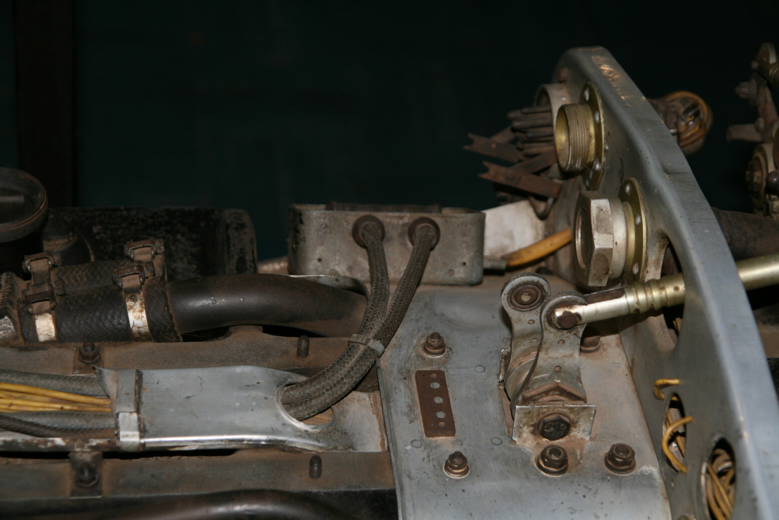
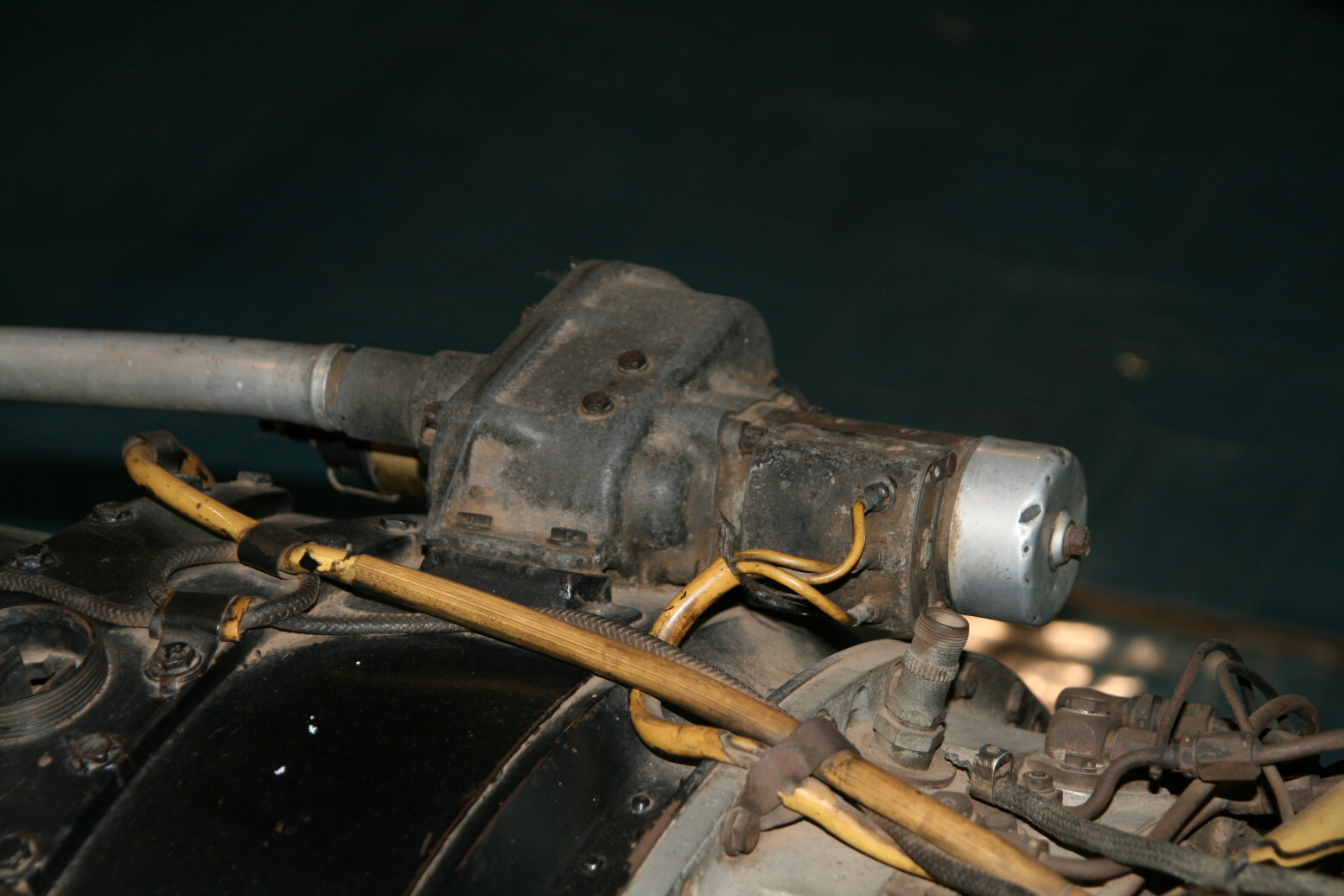
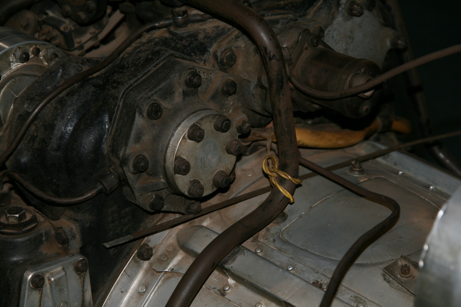
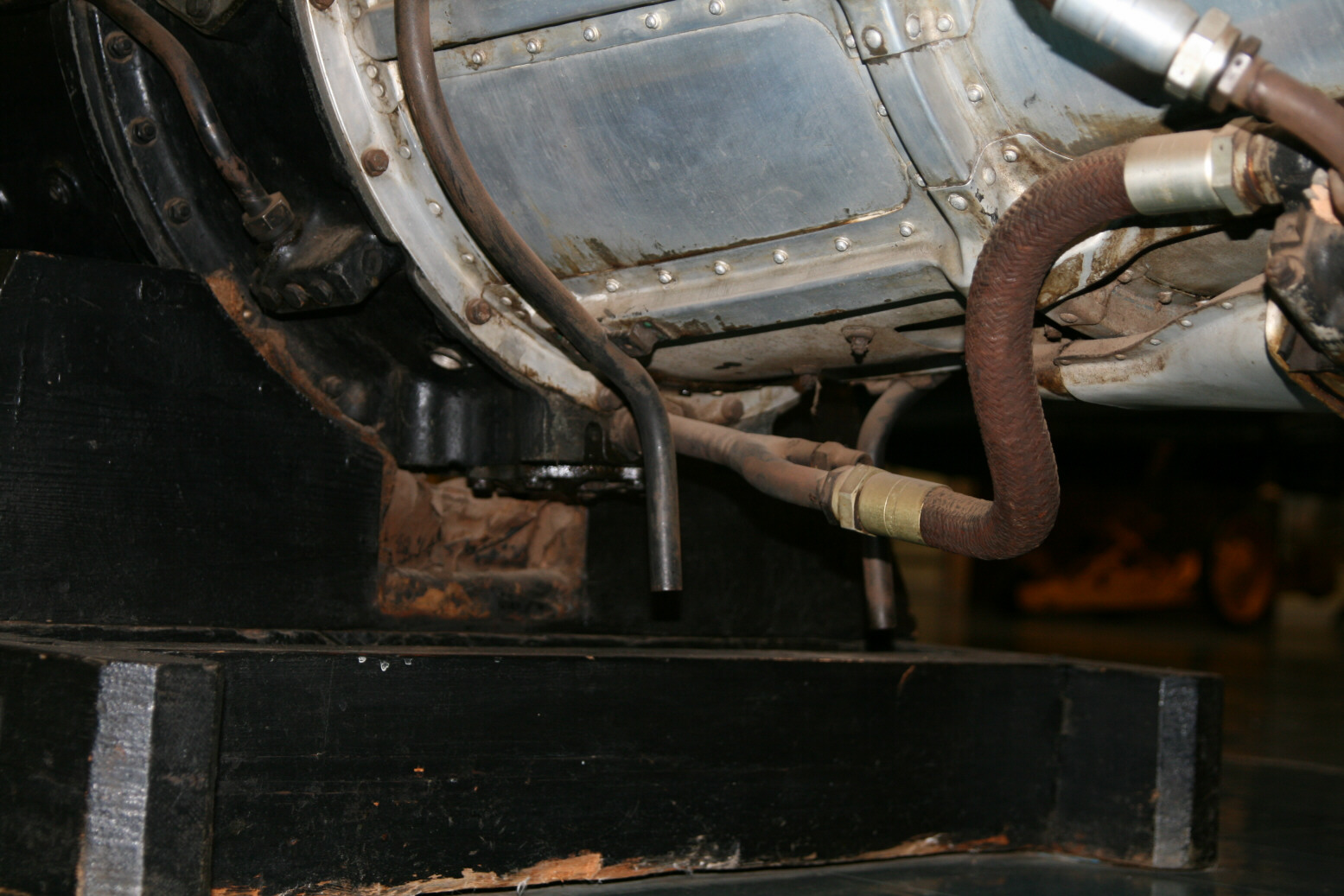
Photos 22 through 24 (above) move further back along the top of the engine. On the right of photo 22 is the throttle rod sticking through the connector plate. There clearly is a part missing behind it, presumably the connection to the throttle in the fuselage. Behind, in the center of the photo is the electrical connection box. The cylindrical black part with a threaded top in center-right of photo 23 is one of the hoisting points (there is another further towards you but out of sight in this photo). The ‘silver’ cylinder on the left is again the tip of the nozzle adjustment rod. Photos 24 through show this from different angles. From the electrical wiring going in it looks like it was driven by an electrical motor. Photo 25 (above) is a bit odd as it shows mostly floor behind the engine but I had to lift my camera up high for this angle so I was shooting blind.
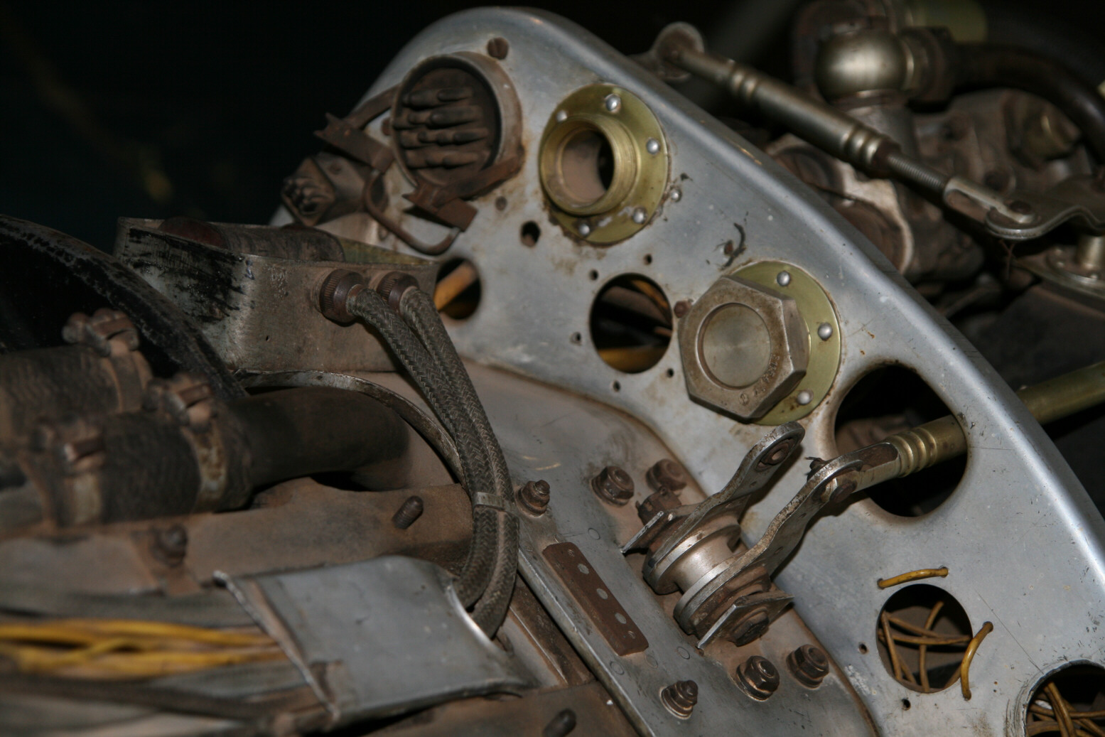
Photo 27 (above) shows the connector plate, also from up high to show the details on the other side.
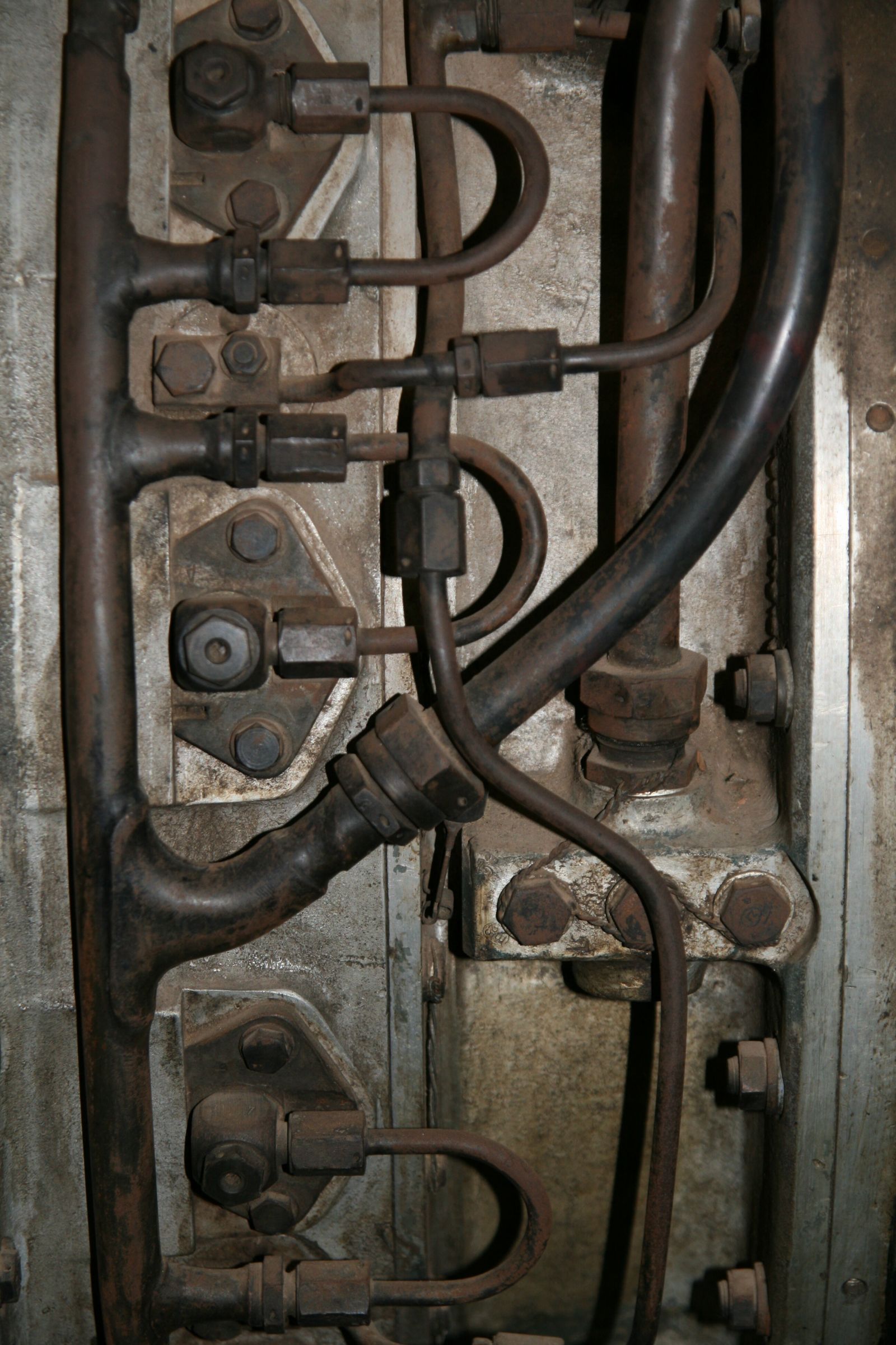
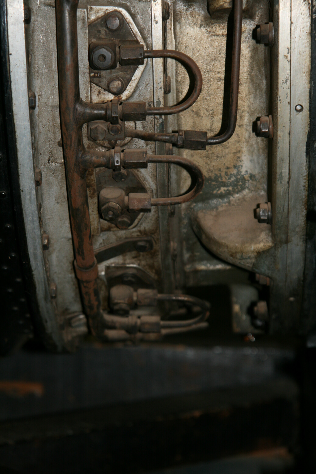
Photos 28 through 30 (above) show the fuel injection lines, going from up to down.
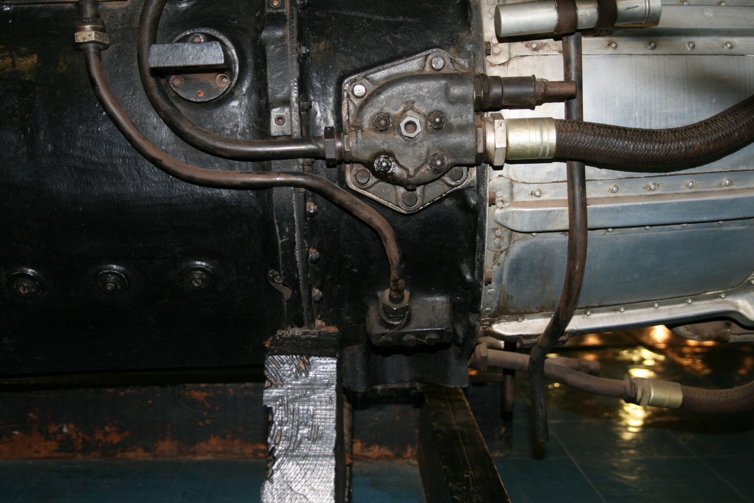
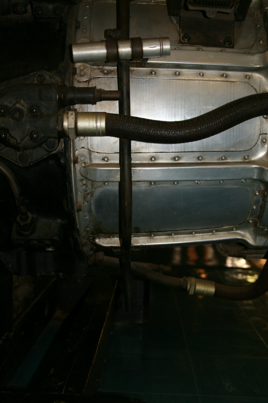
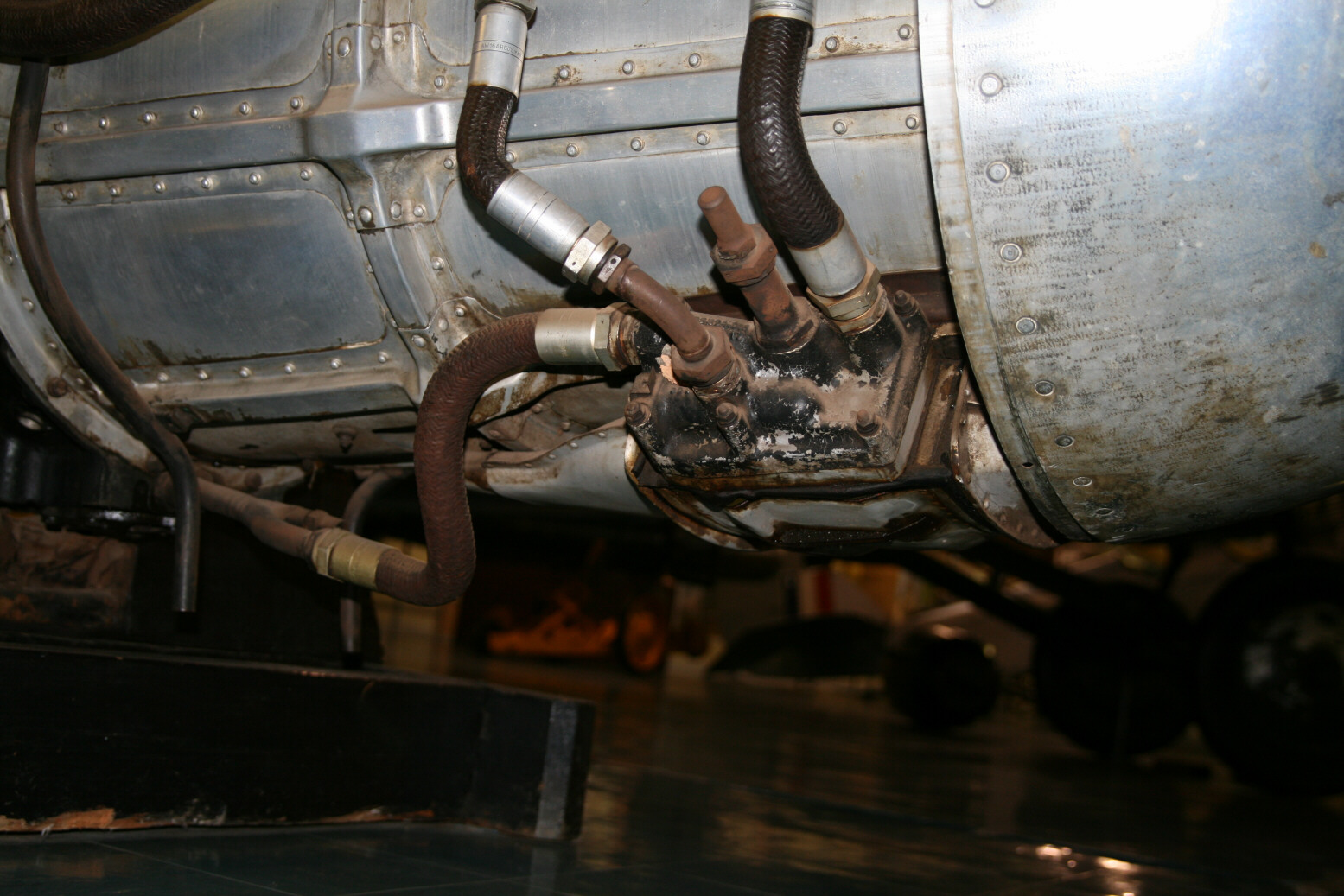
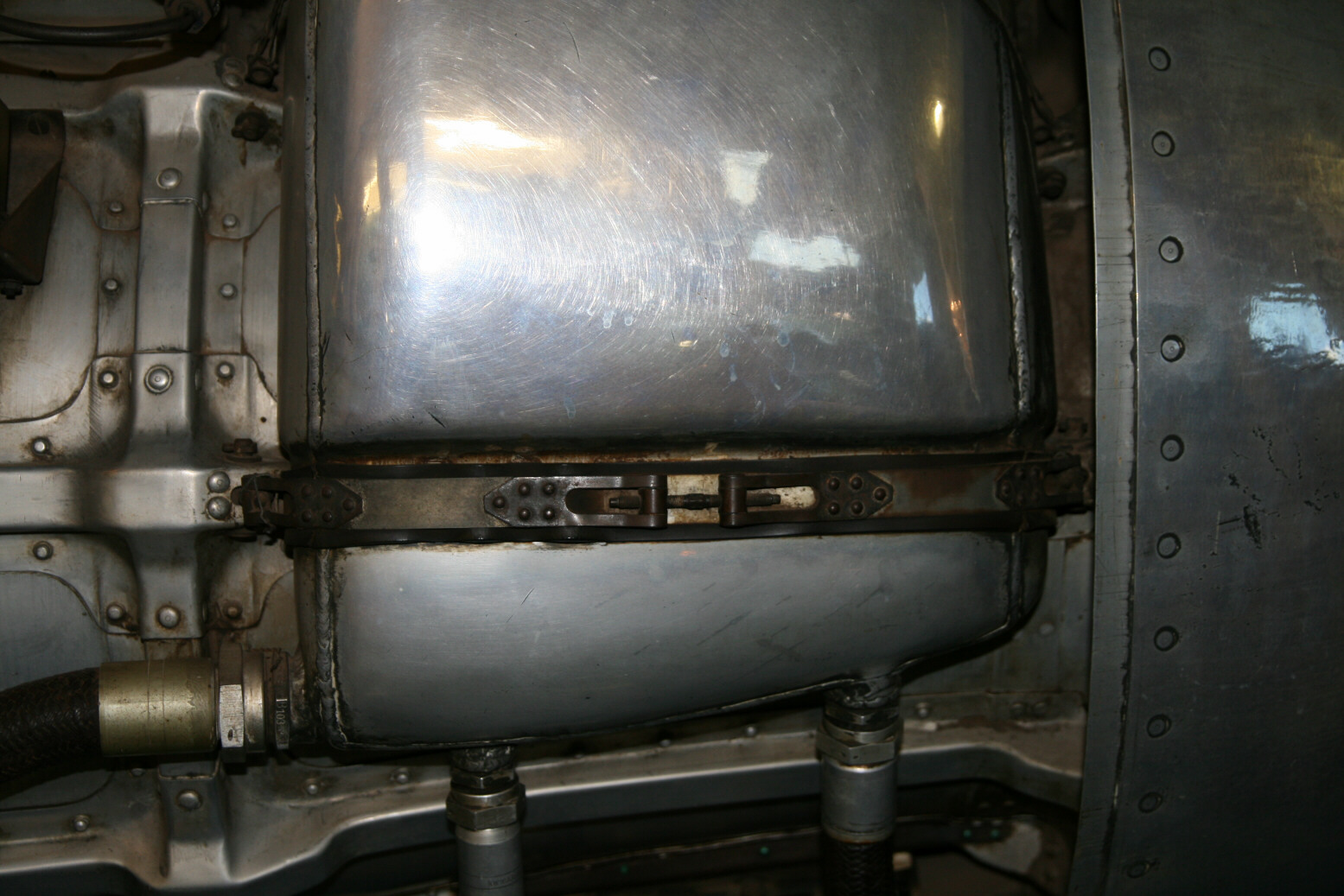
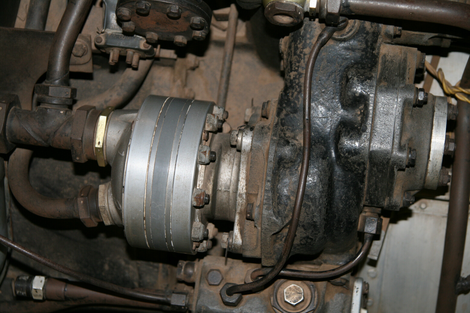
Finally photos 29 through 36 (above) show the oil pump, oil cooler below the engine and the (clamping system of the) oil tank.
© Max Otten 2015
This article created on Friday, June 12 2015; Last modified on Wednesday, March 30 2016